Hardware Hump Day: The Great Ceramic 3D Printer Experiment, Part II
Follow along as Feldi attempts to build a ceramic 3D printer using OS plans she found online.

As parts for my ceramic 3D printer continue to trickle in, I have been slowly moving forward on the great experimental build (see part 1 here). With each step, it has become increasingly clear that the OS plans are more of a general guideline than a set of steps or rules to follow. Much planning, tinkering and redesigning is required to make all the parts cooperate together. I'm starting to understand the need for the Google group, which offers support for individuals attempting to make their own Delta 3D Ceramic Printer.
In all truth, I was hoping to to be much farther along by now. I'm a little disappointed that I haven't gotten more done, but at the same time I'm finding myself at interesting design decisions that I'm looking forward to sharing with you. I’d rather do it right than do it fast, and hey, you get to learn from my mistakes. Lucky you.
Two weeks ago when I posted Part I of The Great Ceramic 3D Printer Experiment we left off here:
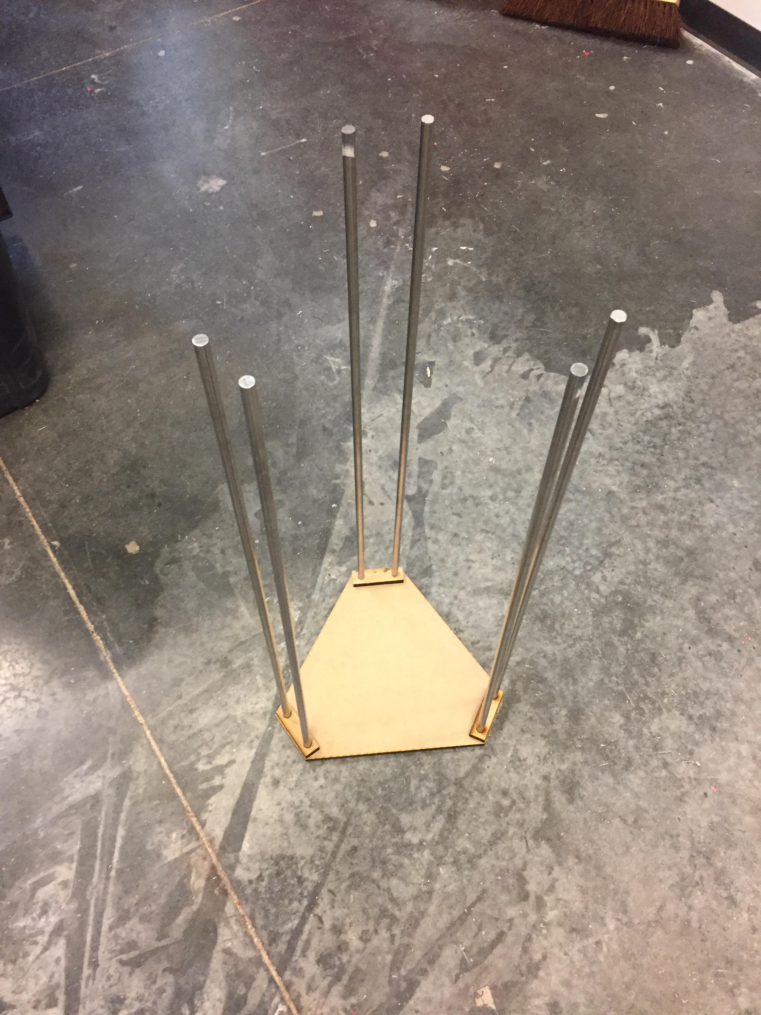
As you can see, my base was in place, but I was stuck there as the couplers had not come in yet and I needed to add them to the rods before completing the structure with the top parts.
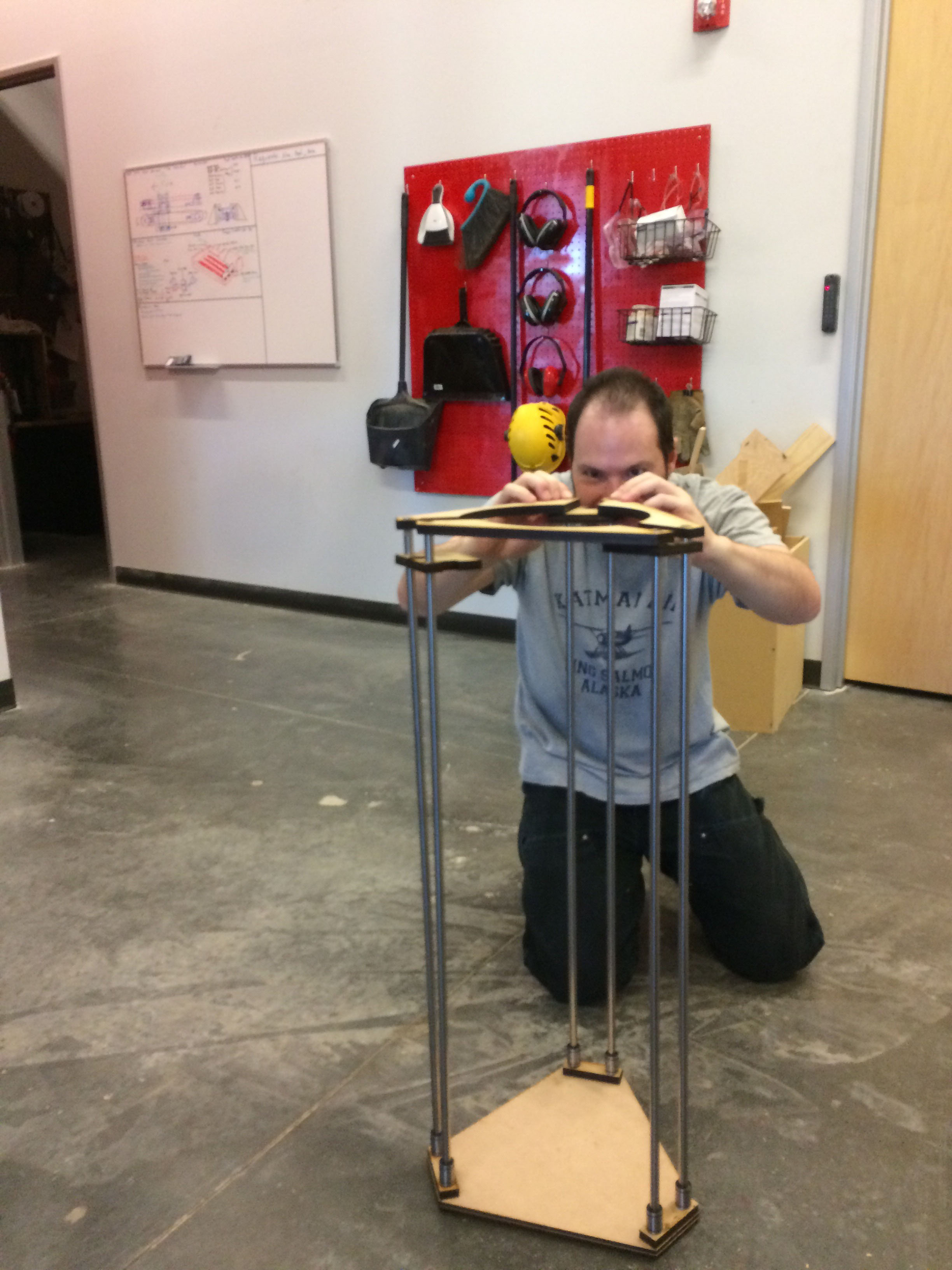
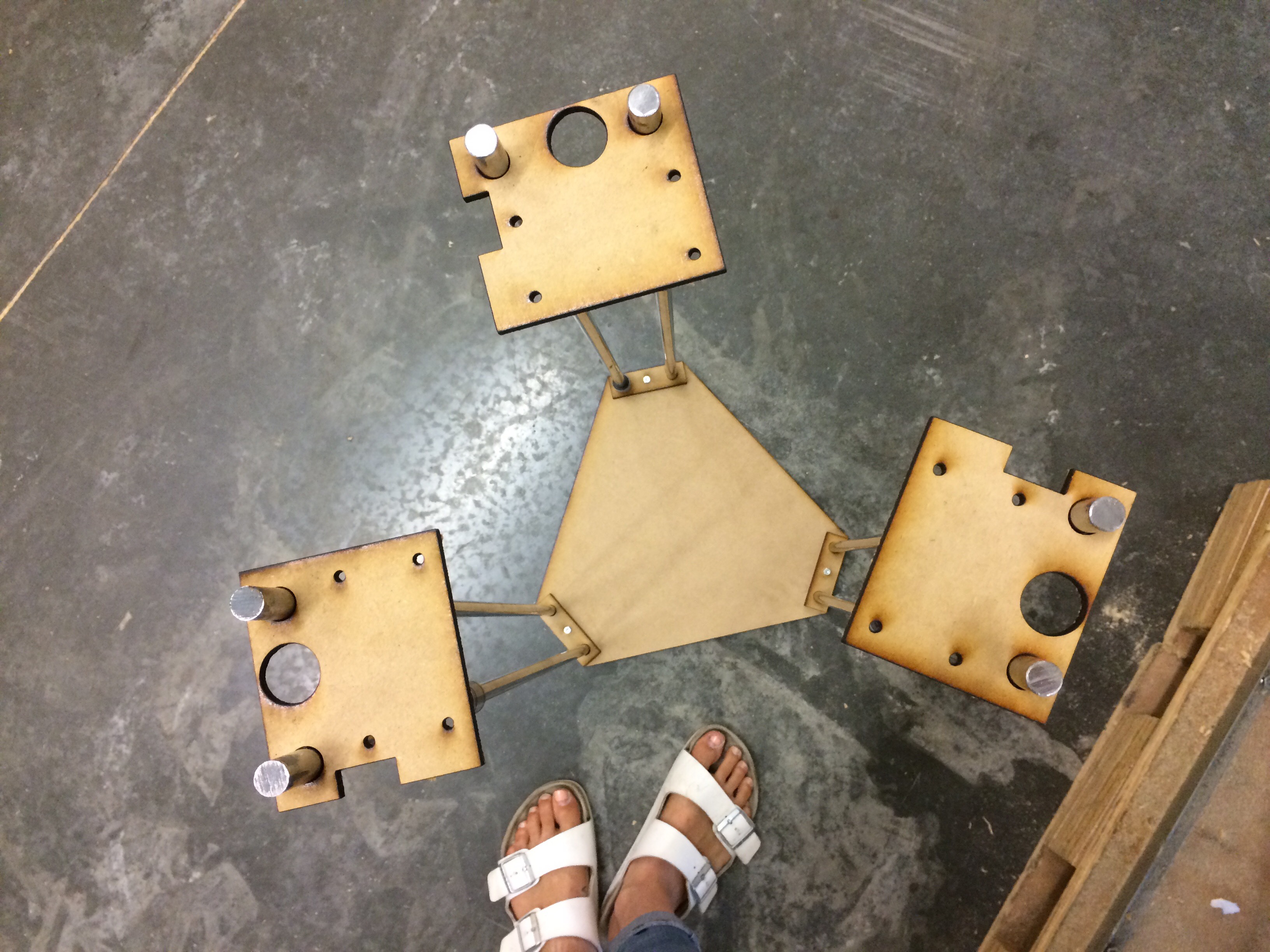
Once my couplers finally came in, I continued on according to Keeps documentation. As I added the top parts, I began to notice that they did not seem to fit as beautifully as they did in Keep’s online video.
My rods were leaning diagonally and warping the shape and form, resulting in a wobbly structure. It was a sad scene and I was quickly losing confidence that this printer would ever come to fruition.
Evan and I spent some time talking about solutions and we decided that the structure could probably benefit from some reinforcements.
I added screws to bind the MDF pieces on both the top and the bottom together. This definitely helped the form feel more solid and sound, but it also looked sloppy and did not ensure any accuracy in the structure.

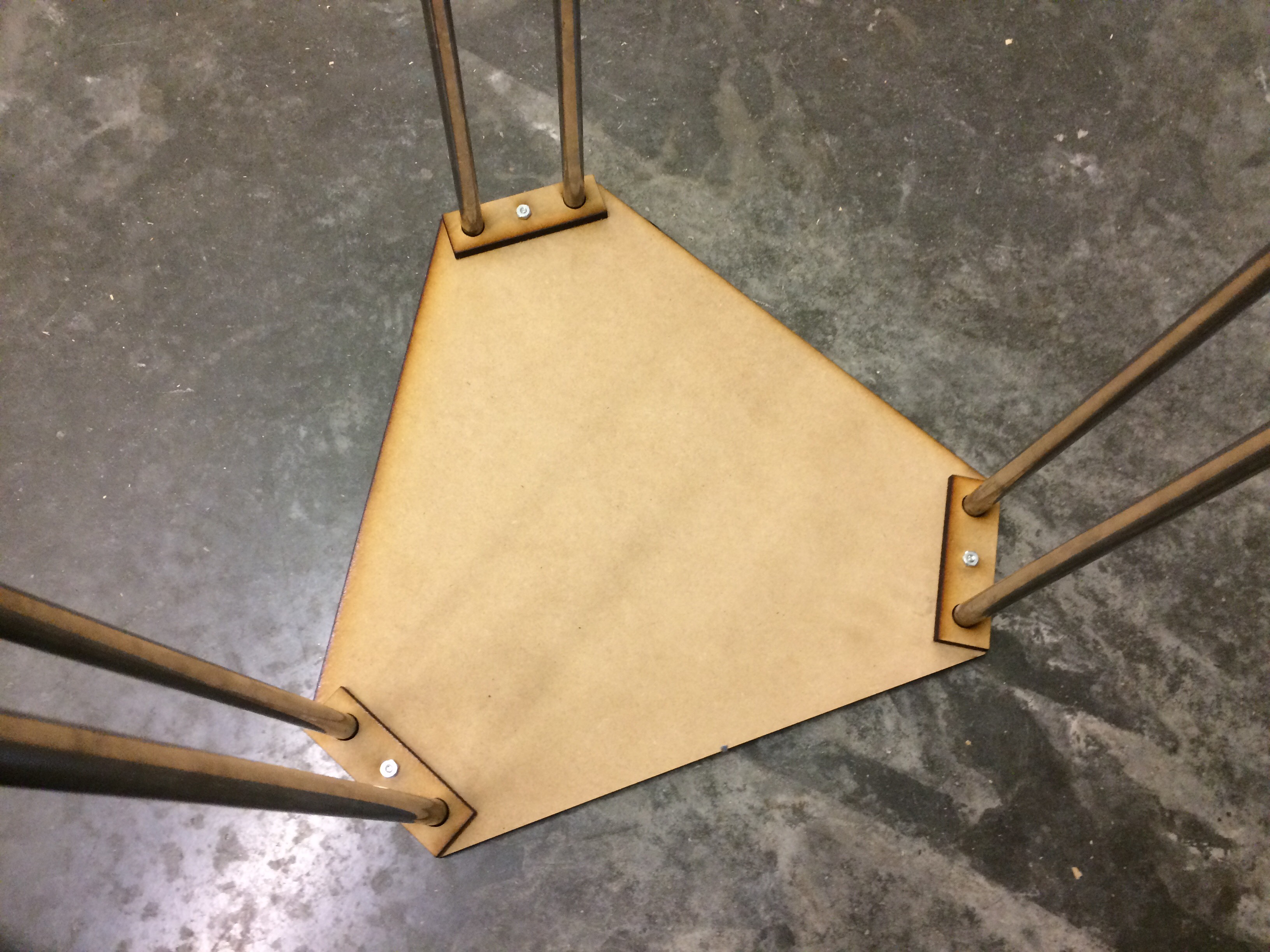
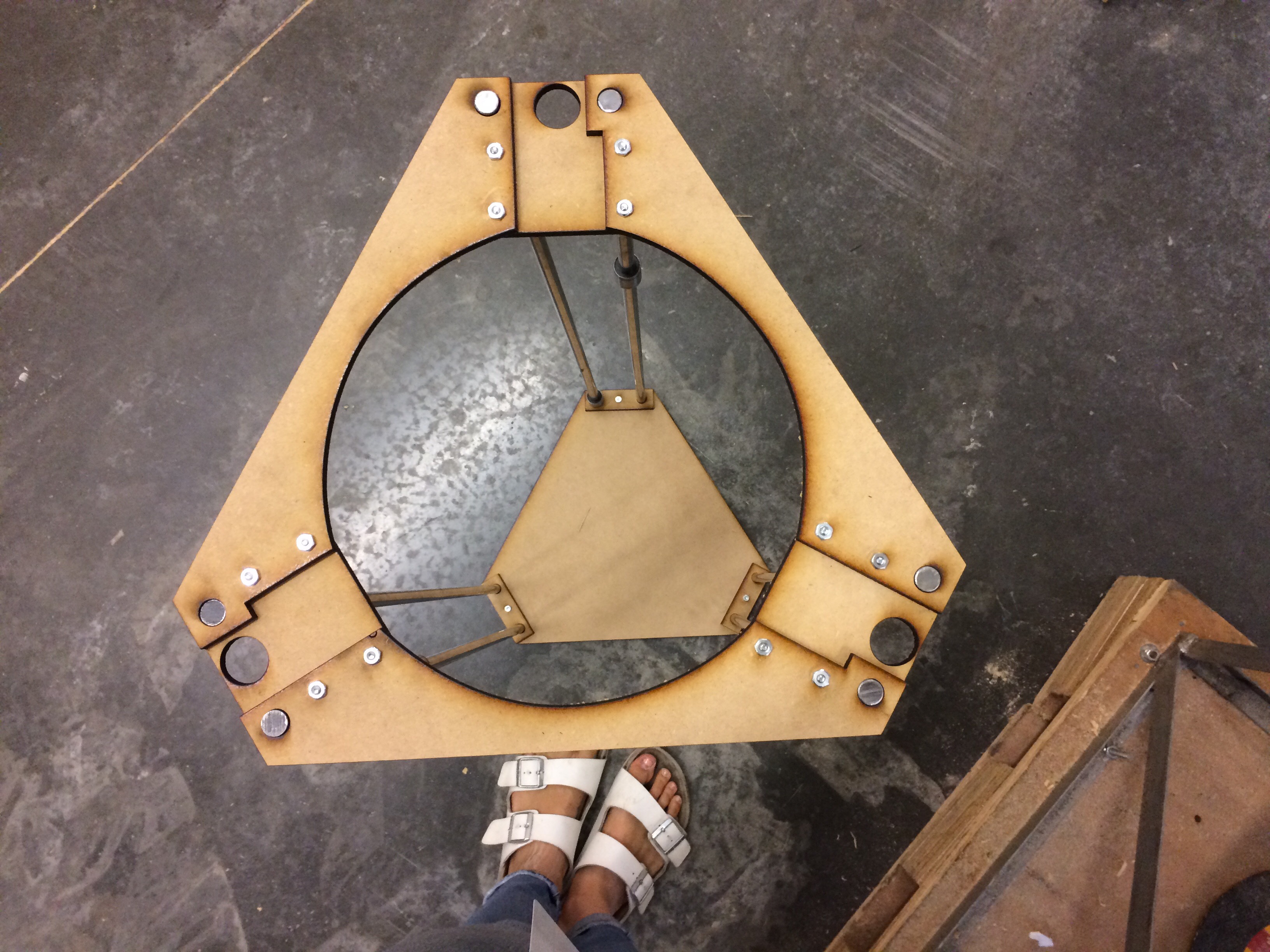
I had also found it was difficult to insert the metal rods into sandwiched MDF. Doable, but very difficult. By sandwiching two pieces of MDF together to increase thickness, I lost the accuracy that the laser cutter offers, and the structural integrity of my build suffered. I ended up sanding inside the rod holes up top with a dremel - only to realize that this compromised the pressure hold. In the image below you can see the the two rods are not flush with the top of the MDF as they should be.

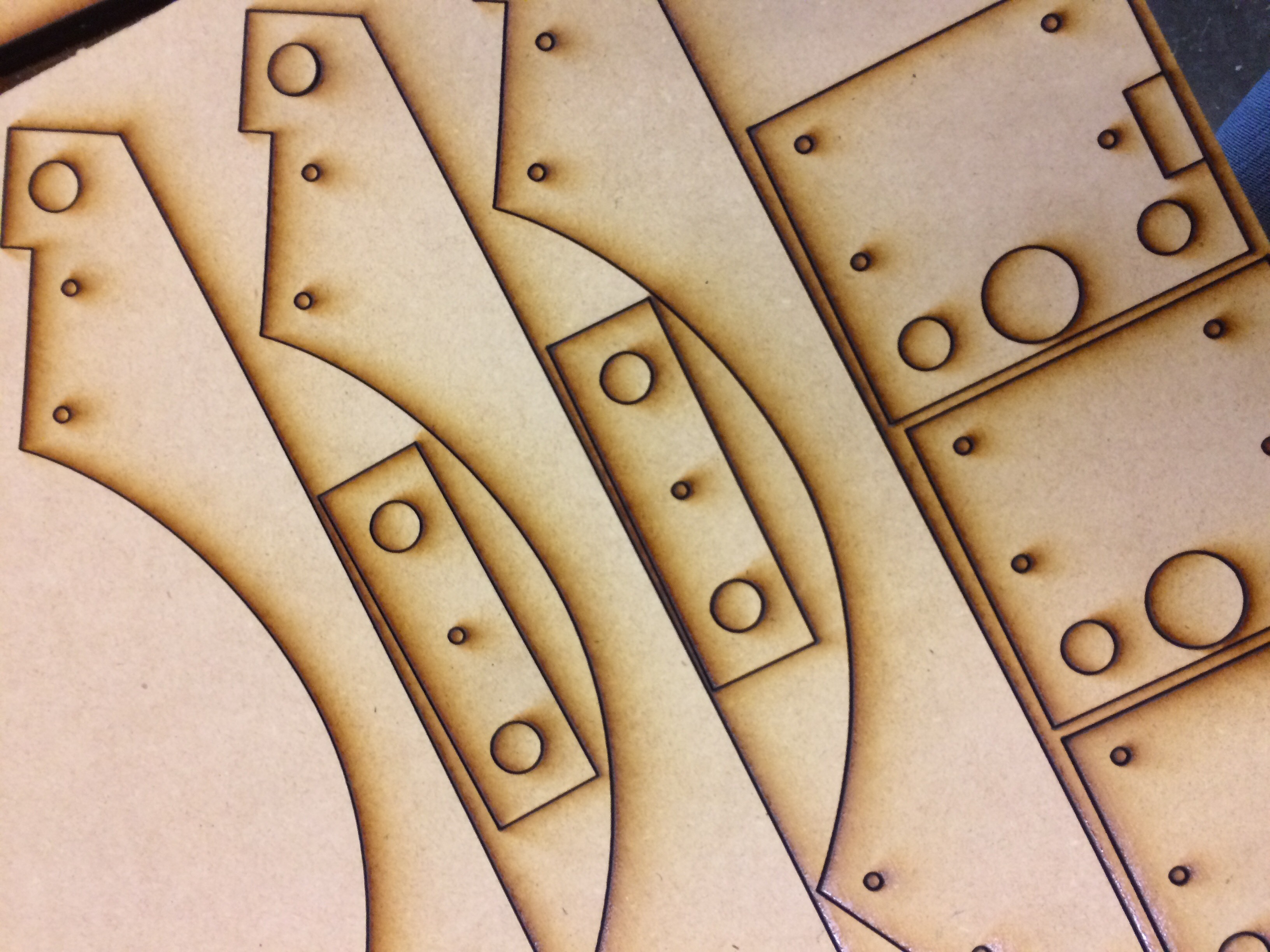
At this point I had accepted both that the pressure hold on the rods was messed up, and the top MDF parts were being held together in a sincerely wonky manner. From my experience using the (very dreamy) Lulzbot Taz 6 3D printer, I understand the importance of using a steady and stable machine when making 3D prints. I believe that starting with an imperfect, sloppy structure will only set the build farther off down the line and result in messy and inaccurate prints. Just thinking about calibrating was giving me the sweats. Because of that, I reluctantly decided to scrap my current build and start over. I recreated my design files (which will be released with full documentation) to be cleaner, and included reinforcement holes to ensure accurate construction and stability. You can see the tiny reinforcement holes in the cut MDF.
Below is my base with small machine screws and nuts holding the parts together.
The couplers were added to the rods and I began adding the top parts.
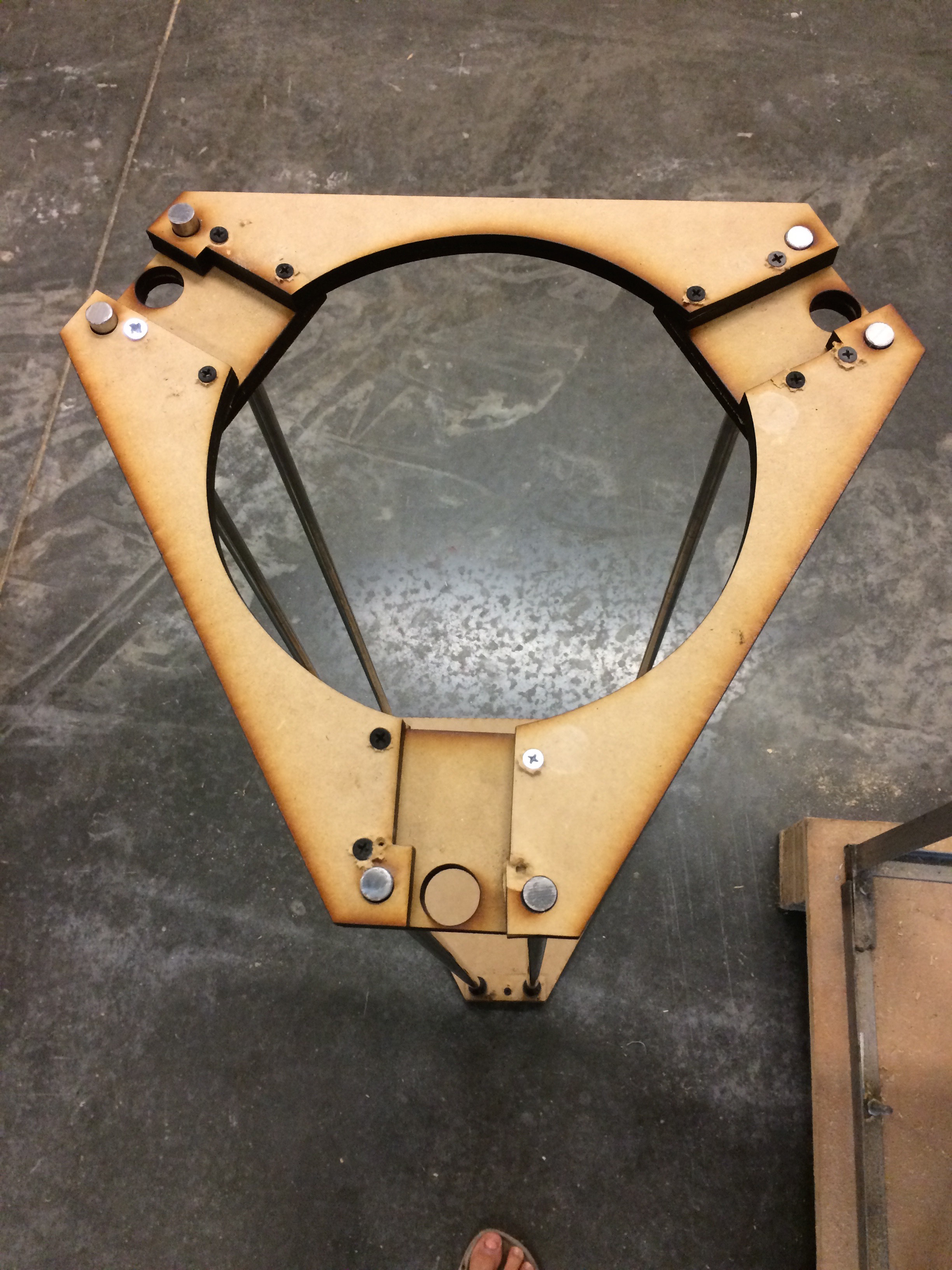
You can see pretty quickly that this design too initially looks warped. This is because we have not added our reinforcements yet.
With the magic of a few machine screws, things started coming together.
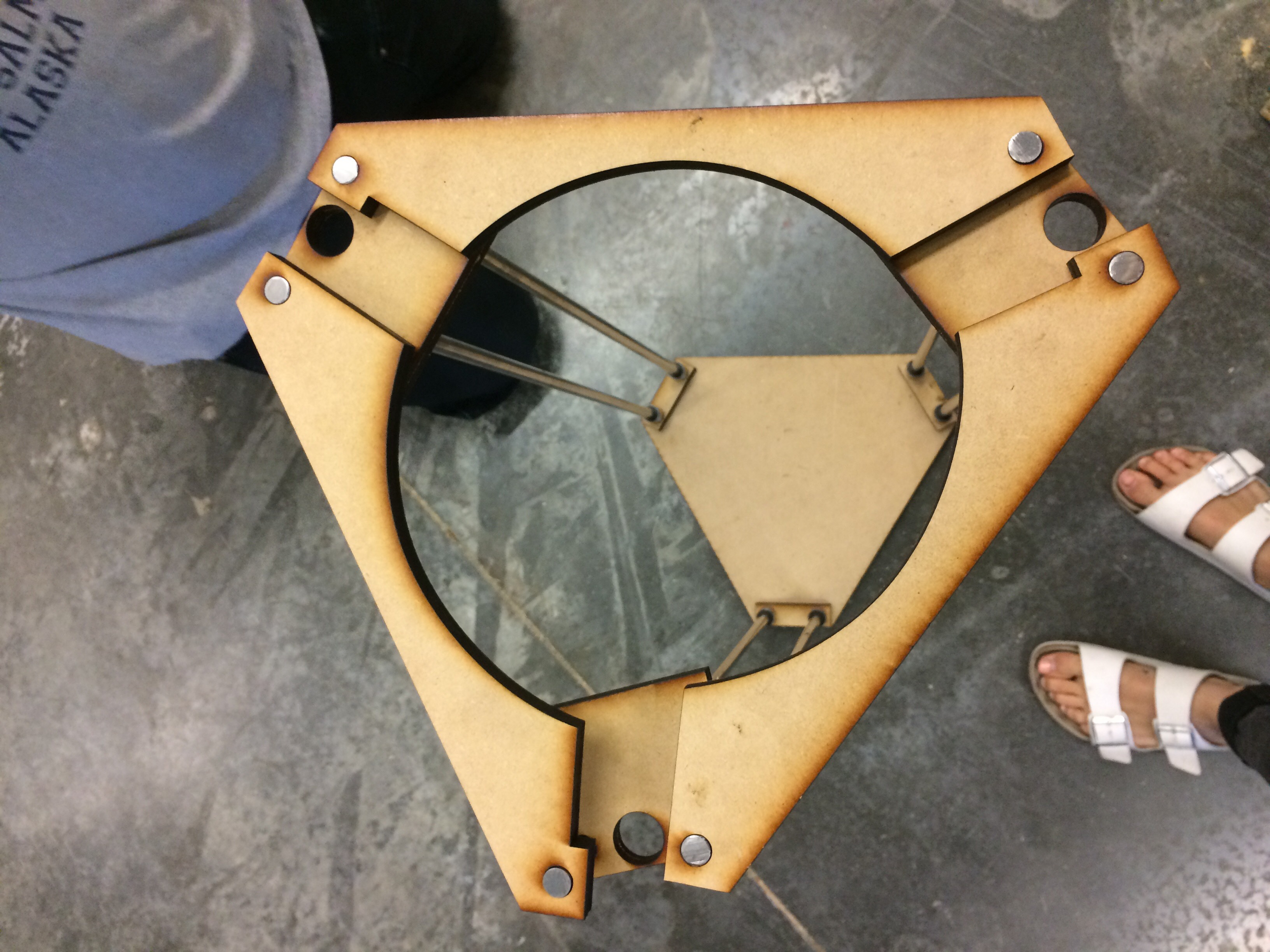
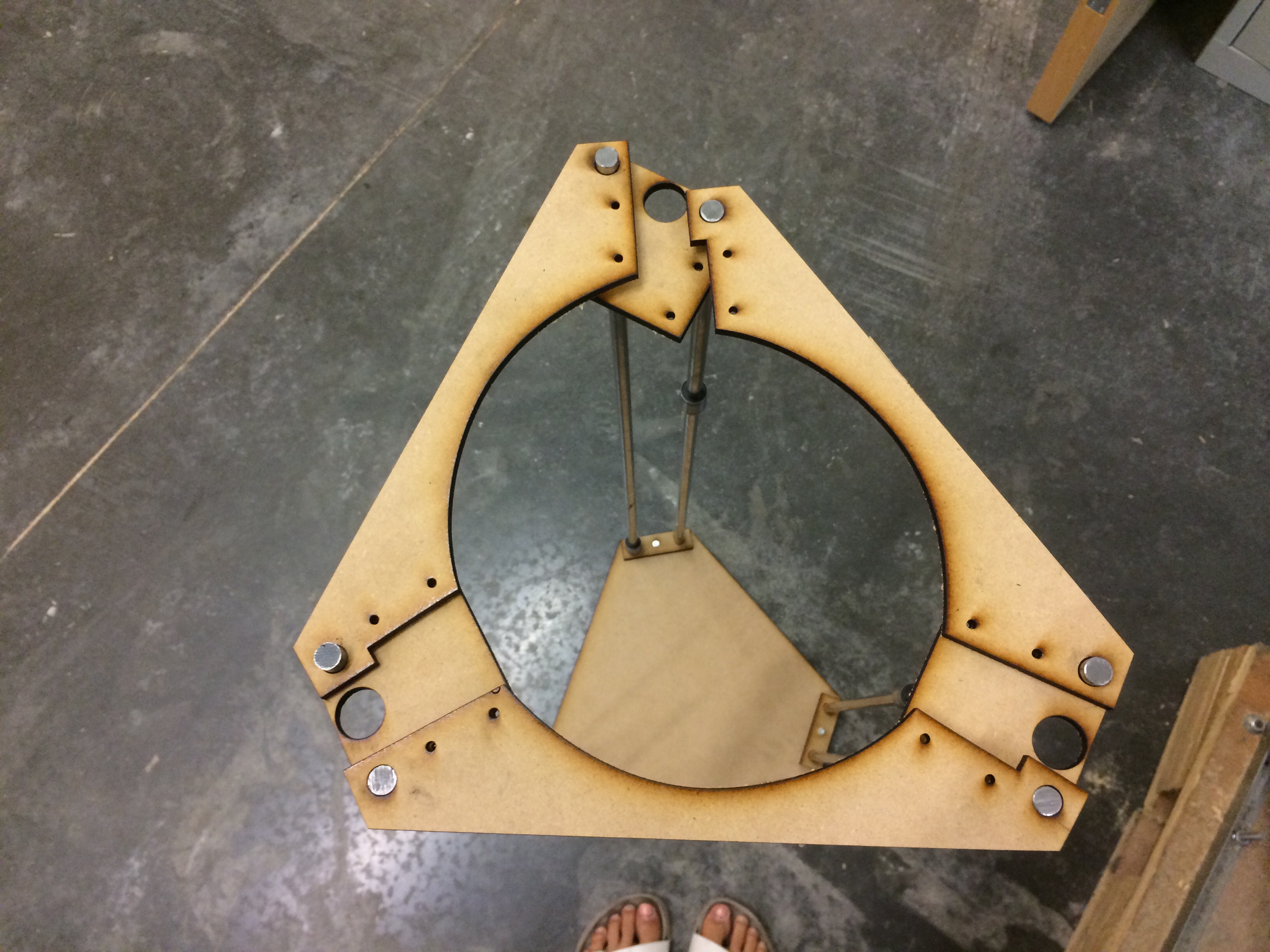
At this point, you can begin to see how the motors should sit at the top.
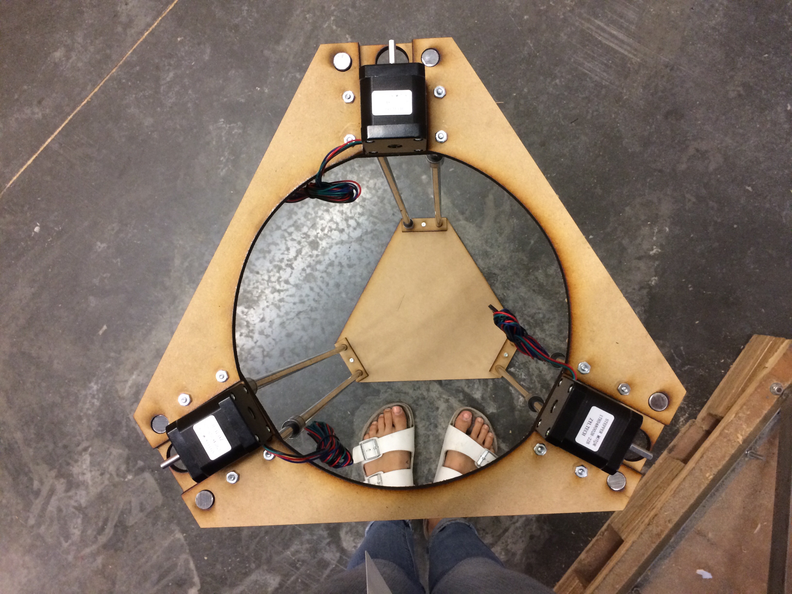
Ahhhhh. So much cleaner. I'll be able to sleep now.
That being said, I still feel like the structure is too wobbly, which is likely due to a) the height of the rods and b) the thinness of the base MDF. In order to solve for this, I will likely trim my rods down to the suggested 70cm and add a reinforcement layer under the base.
My next step is to build the pulley system. As I mentioned earlier, the provided documentation is not terribly straightforward. It's all there - just not necessarily in a clear and cohesive order, which can be rather confusing. While putting everything together this week, I realized that the return pulley is unaccounted for in the bill of materials. While the three pulleys that attach to the motors are included in that bill, Keep only mentioned the return pulleys next to an image much farther down the page. It appears that they are constructed of two 6mm tap washers. I will be sharing the pulley system build in the next installation of this series.
Stay tuned for Part 3 to see how I resolve the pulley system, and share your thoughts, ideas and input on the build in the comments below!


I love it. I can't wait for the next post. 3D printing in novel materials is exciting! Thanks for sharing your challenges as well as your successes. All too often the only thing that gets published is the polished end product, neglecting the rocky road to get there. There's learning for all of us in the journey.
Hello! I am currently planning my own build and would love to check out your bill of materials before I order my own. Please share! Thank you!
I tend to agree with TheRegnirps.
If the structure is not sufficiently rigid after installing the printing platform, I would consider adding diagonal bracing (cable + turnbuckles) from the tops of each pair of rods to the bottoms of the nearest neighboring rods.
I look forward to the next installment!
I would say it is wobbly (wobble and twist) because it is all parallelograms and no triangles. A recipe for trouble. When you get your delta stuff installed it should constrain the system, shouldn't it?
Is this project dead? :( I have been waiting for part III for what it seems forever now!
Nope, not dead at all. We have just been really wrapped up with all of the holidays happening the last couple of months. We'll update you soon!