
Maker education is something very close to my heart. It is a gateway to STE(A)M fields and a great way to learn creative problem solving. Two of the traditional challenges --- barriers to entry --- of bringing electronics into maker education are cost and accessibility.
This week I have been experimenting with different ways to drastically reduce cost and increase accessibility with custom circuit stickers and cardboard circuits that don't remove the circuit design in the process of exploration and play. The idea for cardboard circuits came from DIY Electronic Modules for Tinkerers on Microsoft's GitHub. And the stickers came from the cost constraint of something like $0.25/circuit.
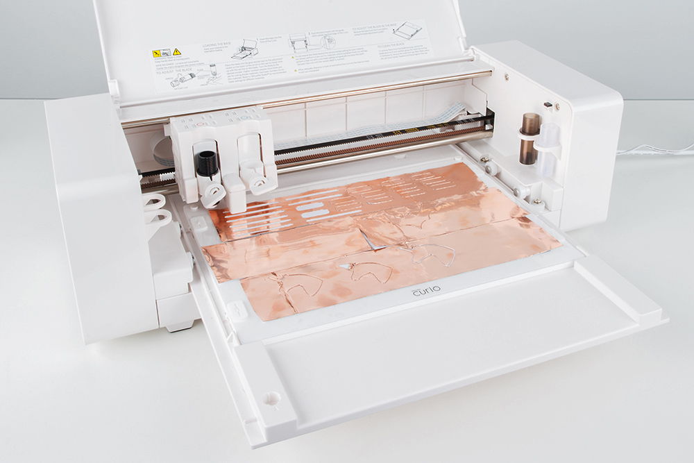
It's hard to see, but the top strip of tape has traces and tabs cut out, the second row has outlines of bats, and the third has outlines of unicorns. The second and third rows of tape are for a cap-touch project.
I'm using the Silhouette Curio, a programmable vinyl and paper cutter, to cut through copper tape. It isn't a trivial piece of equipment, and it is costly at $120 (on sale at Michaels). I still haven't wrapped my head around the software either, which is why the current stickers don't look so nice (but they work!). The end-game is to hammer out the 10 or so essential beginner circuits and get those designs to a die-cutting sticker manufacturer.
At first, I was soldering the parts to the copper tape. Without soldering, a tiny dab of jewelry glue and then Bare Conductive paint dabbed over the connection worked great. I'm now experimenting with mixing different glues in with the conductive paint and characterizing the results.

The micro:bit is a great piece of introductory hardware priced just right at $14.95 and packed with tons of attractive features. One of the features I'm most fond of is how agnostic it is toward programming environments. Beginners can choose the block-based/JavaScript IDE MakeCode developed by Microsoft or the MicroPython IDE, while more advanced programmers can use MicroPython or straight C++ on the mbed platform.
The six teachable moments in microcontroller basics have been drilled into me so well by Jeff Branson that I can't escape them --- and they hold to be very effective when teaching. They are:
Input/Output
Analog/Digital
Read/Write
With these six themes, I created the modules. I've organized the pile by type: rounds are inputs, and rectangles are outputs. For the inputs I made an Electret Mic BOB module, a two-button board module, a photocell module, a switch module and a tilt sensor module. For the outputs I made a buzzer module, an RGB LED module, a servo module and a larger speaker module.
I also have this weird thing --- the bigger something is, the easier it is for me to understand it. Troubleshooting a problem on a breadboard usually means ripping up and starting over. With everything connected through alligator clips and visible/large/labeled traces it is much easier.
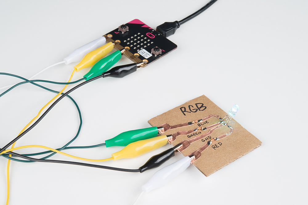
The current-limiting resistors are part of the cardboard circuit. The black spots are where I used the Bare Conductive paint
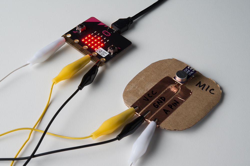
The micro:bit is plotting the analog values on the 5x5 LED matrix, which represent the noise level in the room.
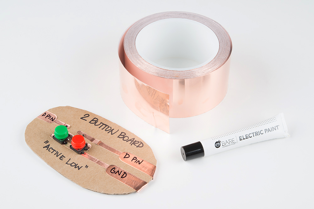
All you need to get started is a roll of copper tape, a few components and conductive paint. One roll of tape and tube of paint can make about 200 circuits.
As I continue to develop around this idea, I want to incorporate ways to up the difficulty. Currently these are single layer, but with the addition of paper or more cardboard and possibly the use of coiled paper clips to use as vias, the concept of multilayered PCB design can be explored. I'm also looking into creating a "library" of through-hole and SMD parts for the Curio machine. I want to get an ATmega 328 DIP in some cardboard and see what I can come up with.
The goal is to not abstract the circuit design as part of the process of learning microcontroller basics and to take a more holistic approach (cost and accessibility included) to learning about circuits and programming.


Back in the dark ages of 1968 we'd copy the schematic from the textbook, rubber cement it to a pine plank, drive in steel thumbtacks at the wire junctions and solder wires between the tacks (following the schematic lines). Passive parts (coils, resistors, capacitors, etc.) were also soldered directly to the tacks, while sockets were mounted for the active parts. The sockets' tabs were soldered to the tacks. It was cheap, solid, easy to build and easy to debug.
Decades before, the plank's resemblance to a kitchen bread board (sometimes because it was actually stolen from the kitchen) gave the process its name - breadboarding. Interesting to see how it's evolved.
It would please me to see and do this - bonus if I can mix in some woodworking.
This is so cool. I'm a maker teacher in middle school and we're about to expand making big time into the elementary schools in our school district. We already have & use a vinyl cutter. Have you taken this project any further? Files to share? I have a few 8th graders working with micro:bit and this could be a great project to do NOW!
Oh, the memories! I am so happy to see this way of building circuits being shown! When I was learning electronics, this was one of the best way to get traction. Reason being is that the ability to rip up and retry something has almost no cost. As indicated as a primary reason to do this, low barrier to entry. Copper tape can be had easily and lasts a long time, cardboard is everywhere, and it is really handy to be able to annotate the circuit. To be fair, when I used this approach it was more for discrete circuits than ICs, and even with tubes (yes, you can copper tape and cardboard a 7 and 9 pin tube socket). It is one of the best ways to have a circuit that works, with annotations, done in an evening. And not be frustrated by stray capacitance and all that. You probably want to get the relatively thin copper tape to avoid having to cut the thicker stuff up. Good job SparkFun in bringing this up!
This seems like a GREAT idea! I do work with teachers and kids in the classroom to build computational thinking skills. Tools and projects that work best for us are the ones that are accessible (cheap and available) and have a low barrier to entry (easy to get started and understand the components). You have checked ALL the boxes.
This is soooooo much more effective and engaging the buying a robot that you "program" to drive around on your iPad. I might add a kid friendly schematic for each of the circuits to help with abstraction skills.
I agree. My heart breaks every time I hear a school bought into the iPad thing. Does it replace books ?- No. Do they learn app development? - No. Do they use it in any way to create technology instead of consuming it? - No. Drives me nuts.
Making your own copper clad circuits on cardboard is very cool but there's a simpler, cheaper solution that's more robust then a solder less breadboard. Why not wire wrap it? They still make pins, tools, perf board, sockets etc. and you can buy all the previously mentioned from Digikey... maybe Sparkfun will stock these items too someday :)
Yes it's archaic (I can hear the snickering) but it's easy, makes sturdy circuits and easy to modify/breakdown
First, I love wire wrap, my first electronics-related job was wire-wrapping circuits in college and I still build wire wrapped circuits today. But I think that this suggestion misses LightningHawk's goal of use as a STEM teaching tool.
For that, the individual modules need to be dirt cheap since there will be a lot of them and because they will need frequent replacement. Wirewrap sockets, pins, circuit boards, etc. are expensive relative to cardboard, glue, copper tape and paint, even if you account for the reusability of wirewrap components. Modules also need to obviously show the circuit layout, and with wirewrap it's all too possible to lose track of which wire goes to which pin, especially for pre-adolescents. Then, there's also the time and tedium factors. While some older students may get into the zen of wrapping, there's always the danger of having a large portion of the class just get bored and never come back (mentally or physically).
I think that wirewrap is still cool and fun and has a place in the home hobbyist/hacker/maker/whatever's skillset, but that it is not as appropriate for teaching beginners as some kind of simpler prototyping approach. LightningHawk's experiments still need some development (especially in the durability department), but have the potential for being a modern update to beginner kid friendly techniques.
Think you missed my point, which is skip the adhesive backed copper tape and use wire wrap to bring the connections to the edge of the board. You'll still use alligators or any kind of jumper to make the module to module connections. I veer from using copper tape because passed experience has shown it will either fall off in a short time or fall off during soldering due to crummy adhesive. Even 3M brand adhesive backed tape does this.
Wire wrapping involves very thin gauge wire, stripping that wire and then wrapping it around potentially hundreds of connections. The circuit sticker method is faster, cheaper, requires much less dexterity and it's easier to troubleshoot. Seeing something bigger also helps with learning. One roll of copper tape with conductive adhesive is $15 and will make 500 2" x 3" circuits.
I'll agree that for the pre-made Electret Mic BOB, wire wrapping directly to the micro:bit would be faster, cheaper & easier. But the point of that module was to test the tolerances of the machine being able to cut hole 0.1" spaced apart. For the RGB LED, with the inline resistors, wire wrapping this during a single class period or during a one-hour intro course at a maker space simply wouldn't happen. So there is a time savings as well without having to sacrifice discussing and being able to view the circuit design.
Using SparkFun's conductive adhesive copper tape, I have actually ripped through the cardboard ripping up connections. So we might have stronger stuff.
My Troubleshooting Nightmare
I'm a little bit late to the party in discovering this article. This such a great idea. I'm always looking for low cost ideas to introduce children to STEM. I'm very concerned about the "digital divide". The cost of some of these nice but rather expensive kits will out of the reach of very low income folk. Thanks for the article and please keep them coming.
What got me into electronics when i was a kid was this kit: http://radioman64.e-monsite.com/pages/les-boites-de-jeu-radio/laffont-electronique-detection-et-alarme.html
Like other kits using those truncated-cone shaped springs, but instead of holes here and there, there was a clever high-density of holes under that you can use to build more complex circuits, but you can cover them with schema sheets for easier initiation on the predefined circuits.
Then at middle school we used wooden boxes with discrete components and banana plugs, which i found rather bulky and spaghetti-wiring prone. Built some of those for my home use, but came back to the former kit until i ran out of those neat springs, then using paired screw terminals (unreliable with thin wires of typical signal components), then learned to solder and went the 'solder leads on tacks on wooden plank' route, until some years later moving to breadboard, stripboard and PCB-etching.
I wonder if those springs can be sourced easily nowadays, as the rest of the kit build keeps relatively low-tech and common parts, only drilled panel and schema-sheet masks, and also keeps compatible with alligator clips.
Check out this Sparkfun blog entry: https://learn.sparkfun.com/tutorials/recreating-classic-electronics-kits
Unfortunately, the spring terminals that are linked in the blog are now retired. Maybe Sparkfun didn't sell enough to keep them stocked, or maybe they were a one-off specialty production run that ran out. If you are very lucky you might be able to get OEM information for that part, but there may be distributor NDAs preventing that. But if you are really interested it wouldn't hurt to ask.