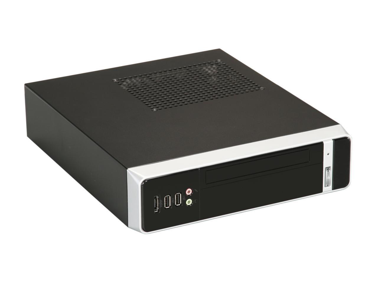
Stupid Arduinos: The RedBoard Pro Micro-ATX
They say, "play stupid games, win stupid prizes," but the joke's on them: I love stupid prizes.

As rewarding as it is to build something that actually improves your day-to-day life, I happen to think — to nobody's surprise — that you can get just as much satisfaction from extravagantly useless projects. If you are one of those who enjoys "making" for its own sake, there is actually a lot to learn from these futile design exercises. Challenges such as the Flashing Light Prize and International Obfuscated C Code Contest are brilliant examples of events that encourage needlessly elaborate solutions to "solved" problems. Often, although the finished product is useless, the technologies and implementations that enable them can have useful applications. At the very least, these types of exercises help to illuminate otherwise obscure aspects of a technology or a process. In the spirit of such endeavors, I'd like to introduce you to a pastime of mine: Stupid Arduino.
Stupid Arduino is the practice of designing elaborate and pointless implementations of the Arduino platform. I chose Arduino as the phrase on which I would be free-style improvising for a few reasons. First of all, it's a popular and accessible platform — far fewer people would be excited about stupid implementations of, say, HyperCard. Secondly, the ingredients for an "Arduino" (in the generic sense) are few and well defined: Any microcontroller with accessible GPIO running the Arduino bootloader can be reasonably referred to as an Arduino. And finally, it's a platform that comprises multiple disciplines: An Arduino can be "stupid" because of its controller, its electrical design, its mechanical design or even its firmware or bootloader design. Stupid Arduino only has three rules: The device must run a functional, Arduino-flavored bootloader; it has to execute the example "blink" sketch (with appropriate delays); and it must have some form of GPIO broken out from the controller. Beyond that, anything goes: fun clock speeds, clock sources, architectures, form factors, power management - it's all fair game.
With that explanation out of the way, I submit the first installment:

The RedBoard Pro Micro-ATX
Let me show you its features:
1) Convenient and well-supported Micro-ATX form factor
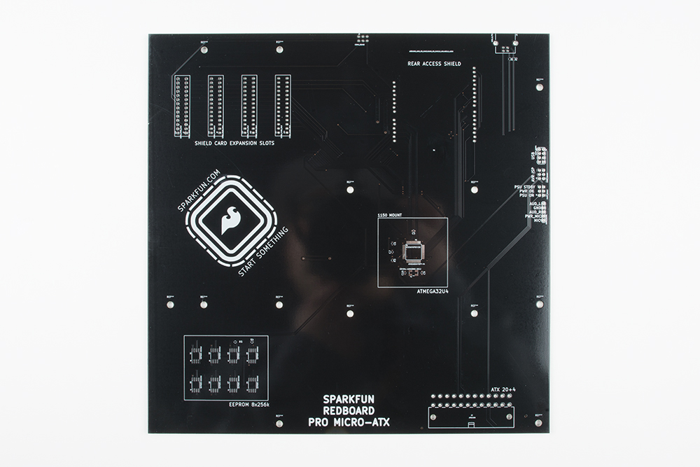
The Micro-ATX form factor is compatible not only with Micro-ATX PC cases but also Standard- and Extended-ATX cases. The Pro Micro-ATX conforms to the mechanical specs for footprint size, stand-off placement and expansion card position for the widest possible compatibility across case manufacturers.
2) Support for enthusiast-grade cooling hardware
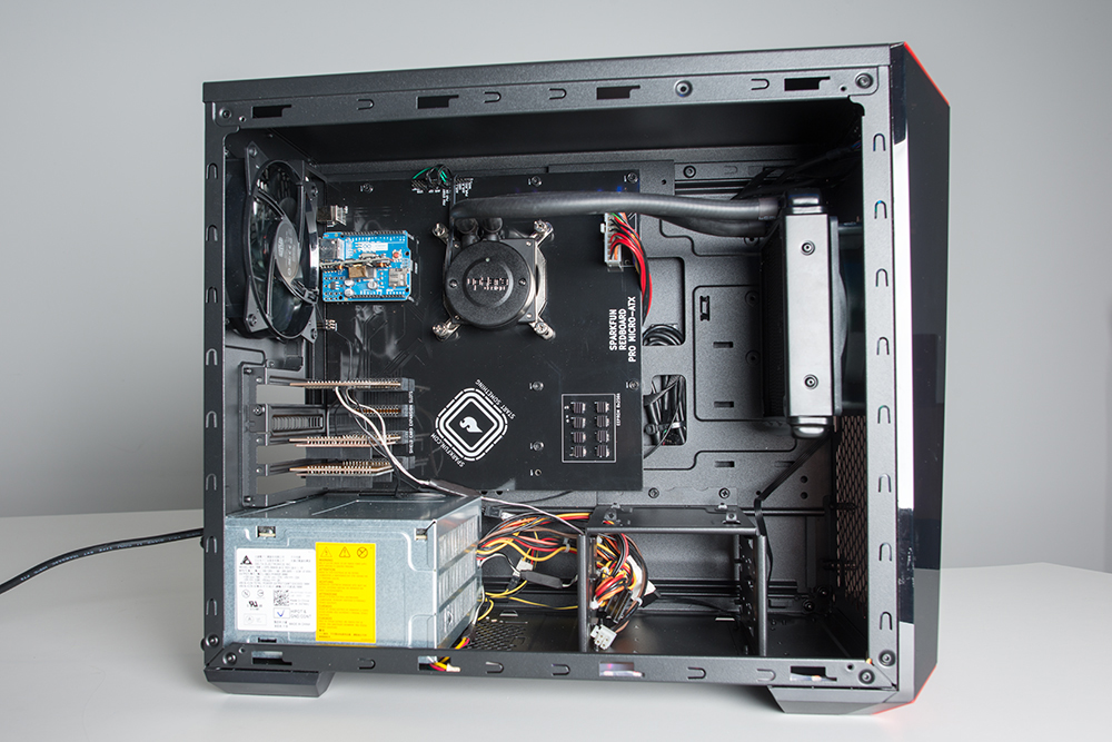
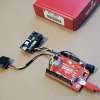
The heart of the Pro Micro-ATX is an ATmega32u4 microcontroller that has been positioned (along with the necessary support components) within the mechanical footprint of an LGA 1151 socket. This gives the user a wide array of options for (pointlessly) cooling the microcontroller, including many AIO air and liquid coolers designed for modern Intel processors.
3) 24-pin ATX power support
Arguably the only useful feature on this board is the 24-pin power connector, which allows the ATmega32u4 and its peripherals to draw from any external, ATX-compatible power supply.
4) Expanded EEPROM
You may be surprised to find that I had, uh, some room on the board. I decided that one way of utilizing this space might be to stack as many I²C EEPROM chips as I could on the one available bus. That number turns out to be eight (with capacities up to 512k), giving this board a whopping 2Mbits of storage! I stopped just short of Shawn's suggestion of laying out I²C DIMM footprints and compatible "RAM cards," because you have to draw the line somewhere...
5) Card Slots!!!
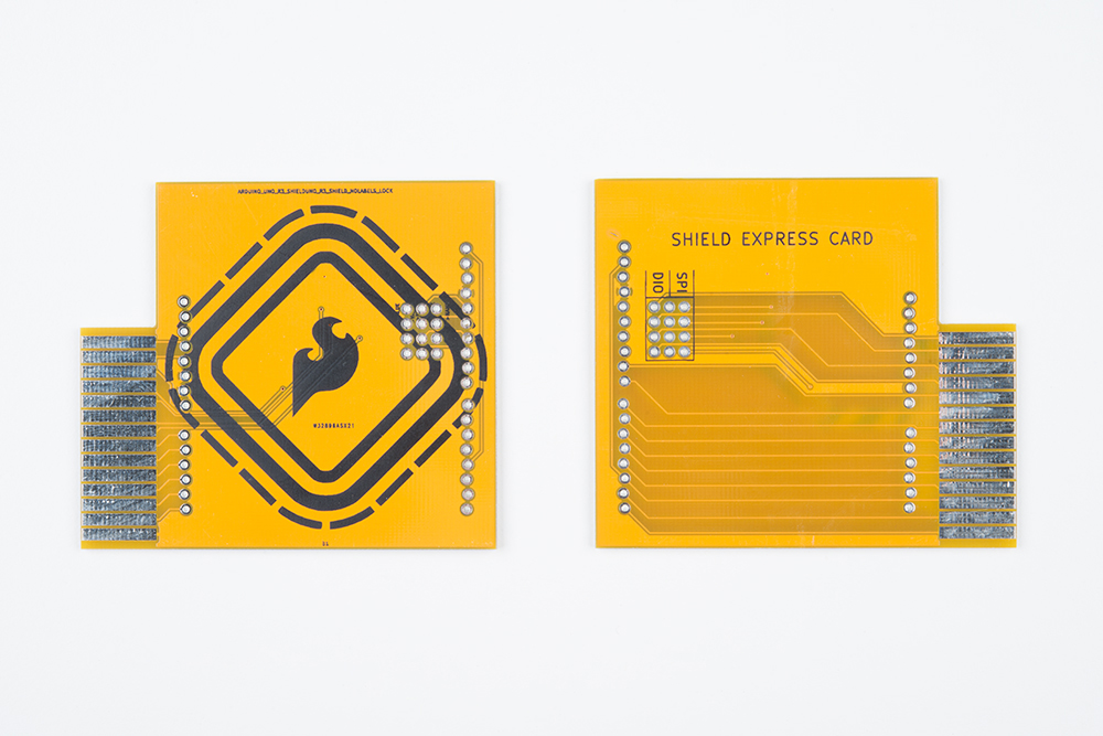
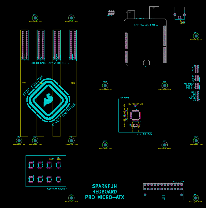
...but NOT at expansion cards! After all, what's a motherboard layout without expansion slots? It's not enthusiast-grade, that's for sure. So I created a system of expansion cards for the Pro Micro-ATX. It could be argued that the Arduino already has a system of expansion cards — shields — and that they are the best possible expansion system given that they have access to literally every I/O of the host controller. I decided that there was no electrical improvement to be made here and that, instead, adapting the shield system to the ATX form factor would be my main focus. I found the idea of using PCI connectors a little excessive, even for an undertaking of this magnitude, and opted for a smaller 28 Position Card Edge Connector. The compatible cards adapt the pinout of the edge connector back to the familiar Arduino shield form factor, so any existing shield can be connected and accessed through the expansion slots in the back of the case.
6) Rear I/O
Any good motherboard has rear I/O and the Pro Micro-ATX is no exception. Accessible from the rear panel are a standard shield footprint, a 6-pin Atmel ISP header and a USB type-B connector for serial communication.
7) RGB Lighting
The oversized spoiler and sweet flame paint job of the custom PC world. Not only does it make your computer faster... it also makes your computer better.
So what did we learn?

Designing to spec
Mechanical specs for ATX and its derivatives are widely published and the topic of a lot of discussion online. This makes it easy enough to grab hold of a dimensioned drawing laying out the card slot, rear I/O and standoff placement. Following these standards allowed me to design a board that fit seamlessly within a random Cooler Master ATX case on the first try.
USB is tremendously robust
Take a moment to admire the USB traces leading from the 32u4 to the type-B connector in the rear I/O window. In the words of Sir Mix-A-Lot, "[They're] long, and [they're] strong, and [they're] ready to get the friction on." And by friction, of course, I mean induction of noise. Those things are antennas and no consideration was made for shielding of any kind. Not to mention the two data lines are, uh, approximately matched length... but they're not strictly matched length. Finally, the prescribed impedance for USB data pair traces is 90 Ohms. Would you like to know what the impedance of my USB data pair is? So would I; hold on a sec... it's about 120-140 (depending on the dielectric properties of this particular FR4) - that's pretty lucky! Anyway, at the relatively low speeds at which this device operates, the USB interface seems to have absolutely no problems!
PC Cases may not be stupid
A microcontroller development board that comes in an ATX tower case is obviously a little... much. However, there are a lot of features PC cases offer that I could see being incredibly useful in certain situations. For instance, if you packed a multiplexer and a bunch of relays into the empty space on the Pro Micro-ATX and then seated it in a reasonably sized Micro-ATX case with a good power supply, that would be a pretty clean industrial control solution. This doesn't just go for Arduinos and PC cases, either. If you have a project in need of an enclosure, look at what's available and design for compatibility!
Card-edge connectors aren't that scary
There are a few types of connector footprints that make hobbyists bristle: FFC/FPC landings and card-edge connectors. Despite many of us becoming familiar with them at an early age thanks to cartridge gaming consoles, card edge can seem mysterious and cumbersome for hobby designs. I'm here to tell you, however, that there's really no fancy trick to it. Pick a card-edge socket and look at the datasheet; it'll tell you the thickness of the card and the depth/pitch of the fingers, and that's all you need! I made custom parts in KiCad for the 28-position connectors that I sourced from Digikey, and it was as simple as making rectangular SMD pads and then spacing them correctly. Edge connectors are robust, durable and relatively inexpensive so don't count them out when you're designing your next widget! Plus, you could 3D-print your own cartridge housings!
Just because it has RGB and liquid cooling doesn't mean it will play Crysis.
The Pro Micro-ATX would get a lot of attention at the LAN party... for a few minutes. In the extreme, this teaches us a lesson that we all probably knew already: You can water-cool anything; that doesn't make it TEH 1337 Gam3r RIG.
Motherboards aren't magic
All that being said, this is a computer, and it only took a few hours to design. There's no magic inside even the most cutting-edge motherboard offerings, and if you can get your hands on the appropriate sockets and I/O controllers, there's nothing stopping you from going full custom on a Ryzen ThreadRipper build... as long as you have a working understanding of high-frequency signal routing and power management. The point is, there's a spectrum between the Pro Micro-ATX and a top-of-the-line gaming PC: You can build a computer of some description without being handed it from on high. There's something nice about that, to my mind.
Are You Not Entertained?

So that's Stupid Arduino. Is this a fun game? Should I make more of them? Is there anything that an Arduino absolutely shouldn't do that you would like me to make it do? Let me know in the comments! Also: because of minimum order quantities from PCBWay, I have three unpopulated Pro Micro-ATX boards and a handful of "expansion cards" left over, so if you would like one of them, say so in your comment and I will pick three people at random to receive a very stupid package!
Update: I almost forgot, you can get a closer look and even make your own by checking out the source over at the StupidArduino Github Repo!
Nick rolled the dice and chose three people to receive a Pro Micro-ATX Stupid Arduino! Congrats to thops, lizclark777, and dwpatter! If you're not one of those three people but you still want to get your hands on one, you can always check out the Github repo to get the design files and order them from OSHPark or PCBWay.


Color me impressed. I'm thinking a raspberry pi compute module slot would be a nice addition, or at least on a adapter card. There's got to be a clean way to integrate a raspberry pi in there somewhere to leverage the strength of both platforms. I use the pi to collect and store the data from my arduino / esp8266 sensor packs.
The ham radio crowd uses ATX power supplies as.. power supplies. They usually chop into them. I've entertained the thought of a board like this to interface and plug directly in- as well as giving info like wattage/amperage. Hmm, might be handy for 3d printers too.
I'm seeing more designs in KICAD from Sparkfun, are you guys migrating away from Eagle?
Right now we are just exploring and testing it out. Thanks for asking!
I'm not sure which version of KiCAD you were using, but for routing the USB lines the latest stable version (and possibly the stable version before the latest, but I'm not sure) does have signal pair routing that routes two traces at the same time, and then there is a tool to tweak the lengths to get matched length. As far as the impedance... That's up to you to calculate. Though the twisted pair transmission line calculator (using 0 twists) might get you close.
Note, if you are using the push and shove router, run your signal pairs LAST. Once placed, the push and shove router won't recognize the pair, potentially pushing and shoving the two traces of the pair in different directions.
That's a good note about the push and shove router, although I rarely use it. As for pair routing I did find that tool after I finished this project because I was designing a custom PCIe riser and was desperate to make that easier. I've used online microstrip impedance calculators for trace impedance in the past (when running antenna feeds for certain designs, for instance) but for whatever reason it never occurred to me during the layout process that there was a recommended line impedance for USB.
Thanks for the tips!
Unfortunately, I don't think the signal pair router will help to route more than 2 parallel lines. (An 8 or 16 line bus router would be awesome...)
The beauty of PCI is that the differential pairs need to be matched in pairs but not across the whole bus. But yes, a wider bus router would be really cool.
Nice stupidity, man! (I never thought saying that would be a 'nice' thing.)
I am interested in an unpopulated Pro Micro-ATX boards and a handful of “expansion cards” left over that you mentioned.
Oh ma gosh. I love doing stupid things just for the sake of doing them. I'd love to play with your stupid thing also. If it were possible (and fair), a pair of the Micro-ATX and an expansion card would be great.
This is amazing. My mind first went to giant MIDI synth with the 32u4. I'd be interested in a "stupid" package 😁
Sir Mix-A-Lot thinks Arduino is for poseurs
https://www.youtube.com/watch?v=rcVwGJ83Ins
Really? I'm not hearing the same message here.
I like it! This is unique. I could actually really put this to good use.
Great project :-) I think this takes a leap towards seriously practical if you used an atmega2560 ( or similar). Having all those IO available via card breakout slots in a micro PC form factor could be pretty cool.
Hilarious. Count me in for the very stupid package :D
I would love to make a stupid project using this board! :)
Could you have at least gave us bigger pictures? =)
As Fry on Futurama would say ... "Shut up and take my money!"
would love the pcb. can you choose me
I would love to be picked for one of the extra boards! Count me in.
Ooo... want! I can has? :D Or I'll have to see about getting Oshpark to make one so it'll be purple :D Then I just need to mount an XLR connector on top of the case to build a modular desk lamp/WS2812B Christmas tree/servo aimed laser cat toy/whatever overly complicated thingy :D
We are actually pretty happy with how much everyone seems to like it, we'll have to talk about bringing this to everyone after the holiday. No promises, though! :D
This is very cool! Doing "Stupid things" is how new things come to be. Sign me up for the drawing please.
This is absolutely amazing. Well done and thank you for sharing! Also, good call on the real world use-case for this type of footprint; that’s worth sticking in the back of the mind.
I would love any leftover boards to play around with myself if you have them!
Please do many more of these!
I would also love one of the extras. A small computer case is a great enclosure for lots of things!
This just made my Friday! In a world packed with single board computers around every turn, all of them having more horsepower than my first PC this seems like a true step backwards just for the sake of fun. I too would love to get my hands on one of your spare boards just to be able to show it off to my computer building nerdy friends for a laugh. Thank you for this, Nick!
This is just so stupidly awesome! Seeing the watercooler made me chuckle. :D Sign me up for the drawing, please.
I agree with the earlier comment that this would be a fantastic way to package components for a rapid prototype printer.
I too would be interested in one of the spares to experiment with.
I really enjoyed reading this, and would love to try a similar build. Perhaps one with multiple microcontrollers and a Pi compute module for an ultimate on-the-go development box.
I am also interested in the unpopulated boards, as it would be a great confidence-builder in designing my own.
Hah I actually have an unused PC case standing around at home and that would be a pretty stupid use for it... so I'd love to get one of those packages XD
Honestly though, that's a pretty cool idea for a project. I've always wanted to make a small computer with expansion slots, similar to this ^^
Can I have one pls? It's really cool!! Pls Its the stupidest (coolest) thing I see ever. Can you guys sell them? (Sry for the begging, its just cool, but pls.....)
BTW I am not joking, I would really like to see them sold!
Even though it's "stupid" it sounds like it was a lot of fun to make. I am interested in one of the extra Pro Micro-ATX boards and expansion cards.
i can haz pcb?
But for real though, nice write-up. I've been trying to figure out how I can make an enclosure for an industrial control thing I'm prototyping, great thing I read this guide. Keep making for the sake of making!
Wow very interesting and stupidly useful. I would love to have a Pro Micro-ATX board and an expansion card. I would use it as the base system for a distributed I2C data acquisition system.
This is quite possibly the dumbest thing I have ever seen. I love it.
Very cool, but not really all that stupid. I could see uses for things such as this.. Hence:
I am interested in an unpopulated Pro Micro-ATX boards and a handful of “expansion cards” left over that you mentioned.
Just what I wanted for Xmas...if you can send me one...that'd be awesome...
Oh man. This. Is. Fantastic. I don't know what I would do with it yet but I would love the chance to play with it :)
Love the idea of taking the more niche arduino and combining it with more know PC hardware formats. Would love to put my name in for the extra pcbs.
Stupidity may be contagious - I'll enter the drawing for a very stupid package!
I would like to get in on this. Pro Micro-ATX maybe the perfect solutions for something I have had in mind.
I want to build one !!!!!!
I love the use of 'Card Slots', very clever! I have a spare PC case (or three) knocking around, and would love a chance to, ah, expand the reach of the Stupidity ;) Definitely interested in an extra board if one is available!
That's wonderful. Is that a fan header? If not, there should be a fan header with the PWM and tach leads routed for fun fan games (using the fan as a random timing generator?). I'd also put a floppy header with a couple of signals routed to allow playing music with the floppy mechanism. Maybe serial or even parallel ports. A few power transistors or relays with jumpers to connect them to the beefy power supply to control higher power loads (CCFL inverters?). I suspect it's possible for a 32U4 to implement enough signalling to support the original ISA "bus", but that's a little silly. Maybe headers to light the usual front panel LEDs, run the beeper, and give access to the switches.
Yes, those are all awesome ideas! There are no fan headers, but I did break out the reset switch to a header that I could plug the case's power switch into and the first blink test I did was performed on the HDD activity LED. I have the PSU headers hooked up for standby power LED and power enable the way you would find them on a real Mobo. I also put an HD audio header on the board but didn't route it to anything (my plan was to route some GPIO to the headphone jack for tone library output)
If I did another rev of this board I would definitely add a bunch of the stuff that you mentioned plus I would add a configurable on-board clock gen for overclocking.
Overclocking would be a good excuse for liquid cooling an Arduino. ;-)
Outer layer copper thickness necessities ought to be reviewed as trace dimension and spacing decrease below 5-6 mils. The designer ought to attempt to utilize a copper callout to satisfy the electrical necessities additionally as take into account manufacturability of the PCB. A general rule is (1 oz. copper being nominal) as circuit density will increase, copper weight ought to decrease. as an example, a four mil trace and house style ought to utilize [*fr1] ounce copper for external layers where doable.
Continuing this fun nonsense, if there's a configurable clock generator, there should also be a configurable power supply to tweak the supply voltage (also useful for overclocking). Of course, you'll need another microcontroller to control the power supply and clock generator. At this rate, we're going to fill that board! Now I'm getting tempted to lay one out myself.