Story of a SparkFun AVC Rover
The multi-year adventure of building JRover from scratch, as told by its creator

Jesse Brockmann is a senior software engineer with over 20 years of experience. Jesse works for a large corporation designing real-time simulation software. He started programming on an Apple IIe at the age of six. Jesse has competed the last four years at AVC, and won in 2016 and 2017.
I first started working on my SparkFun AVC rover back in 2011, but I didn’t have a finished rover until 2014. I first heard about the competition on the SparkFun site and thought AVC would be a great challenge – even then I thought self-driving cars would become mainstream. I hope I can provide some useful information for those of you working on or considering making a rover.
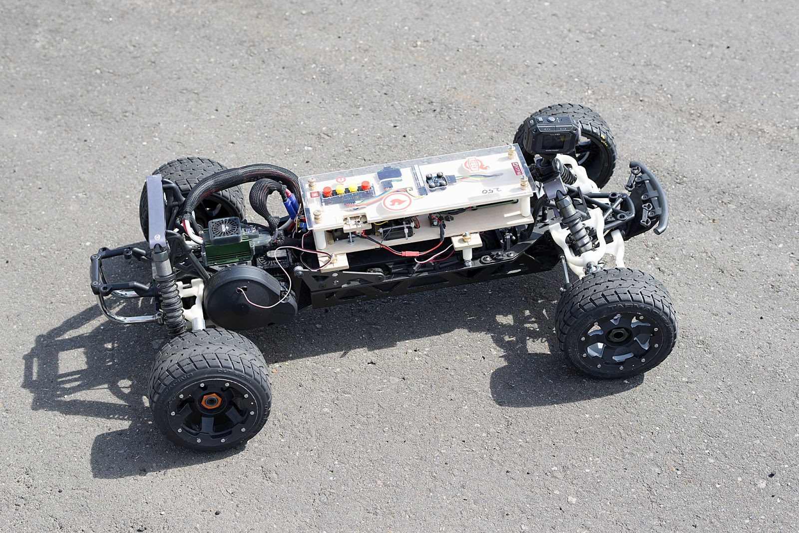
My latest rover uses the following components:
- Traxxas Slash 4x4 Platinum LCG Truck
- Anaconda street tires
- Traxxas RPM sensor
- RC4WD 35-turn brushed motor
- Castle ESC
- 3S 5400mah LiPo
- Teensy 3.5
- 2GB+ micro SD card
- BNO-055 IMU
- Headers
- Various jumper wires
- Tactile Buttons
- Custom JRover Baseboard and Button Board
- Digole 2” LCD display
- Airplane RC transmitter and receiver with PPM output
- USB battery bank
The most important parts of the rover are the Teensy, Inertial Measurement Unit (IMU) and RPM sensor. The IMU provides a heading, the RPM sensor determines the distance traveled and the Teensy is the brains of the rover. The Teensy 3.5 runs at 120mhz with 192k of RAM and has a SD card slot.
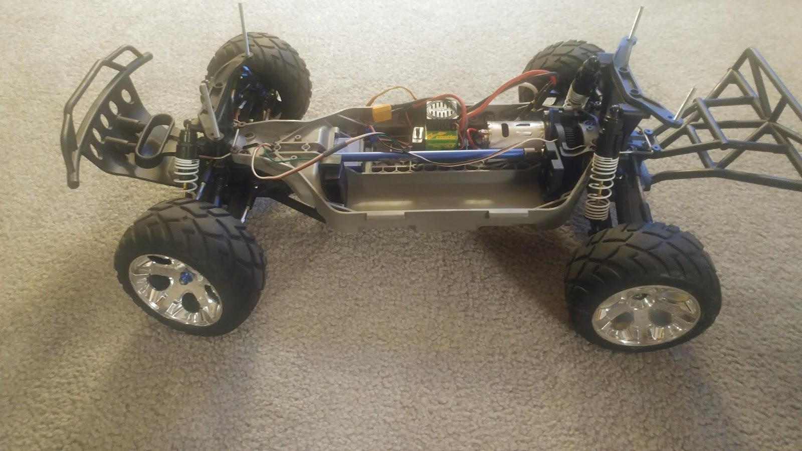
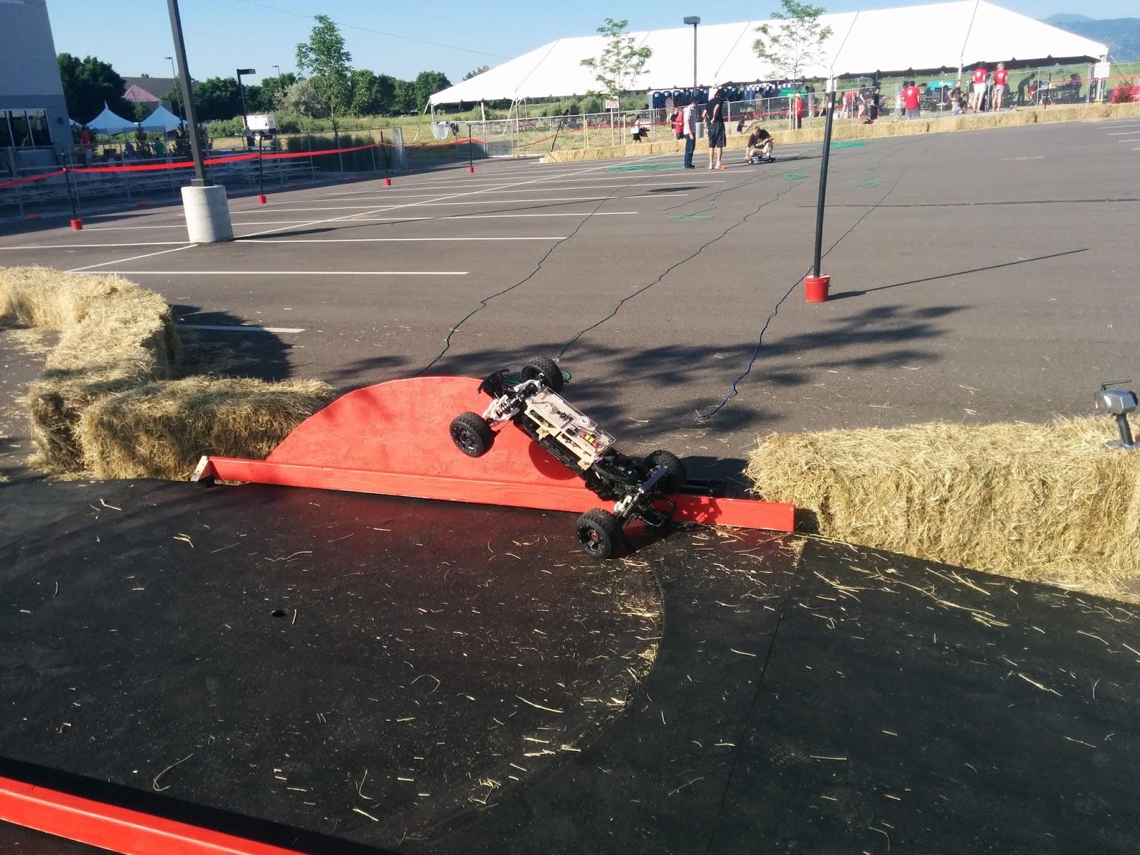
Another important part is the base platform. I chose the Slash 4x4 Platinum LCG (Low Center of Gravity) for a few reasons. Four-wheel-drive gives better traction, which lessens wheel slip that can cause errors in the location. A Slash can better handle some rough spots on track, but I chose LCG because it doesn’t need two or more inches of clearance. The Slash Platinum has upgraded parts for the knuckles that are less likely to fail upon impact with a hay bale, curb or barrel. It also has sway bars that improve turning performance. For street use I’m using Anaconda tires, but I am researching the best tire to use for a packed dirt surface. A 3s 5400mah LiPo is used to provide long runtime and enough speed/power, even with a brushed motor.
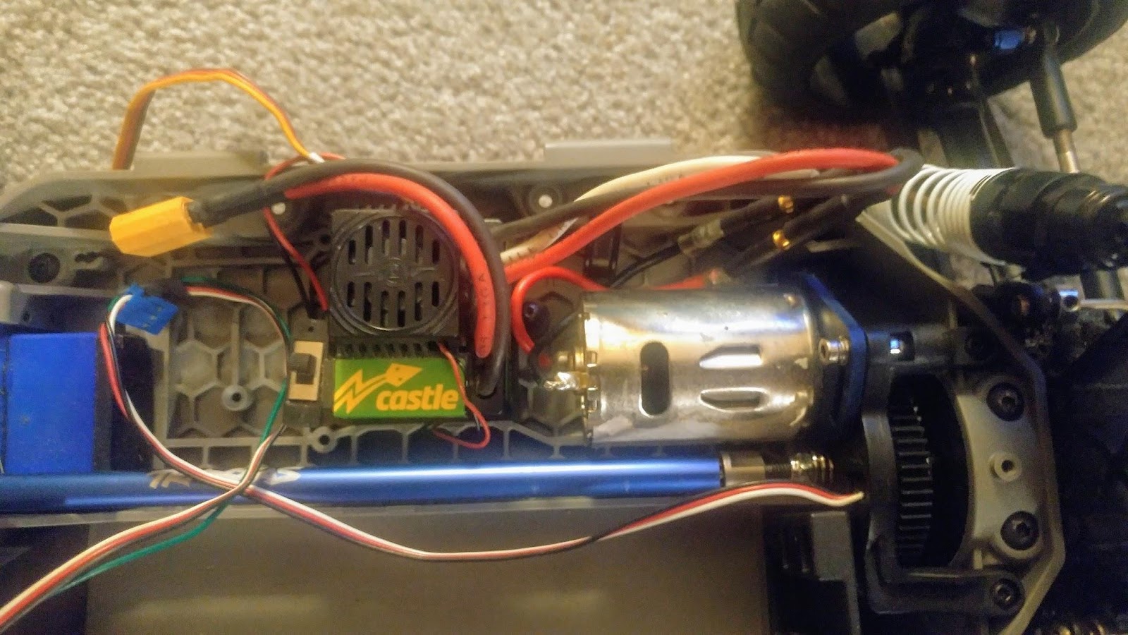
I use a Castle ESC because it's programmable and has better failsafe behavior compared to the Traxxas ESC. I’ve had Traxxas ESC to full throttle when signal was lost. I’m using a 35-turn brushed motor for better slow-speed performance. During testing, this allows the rover to drive very slowly (less than 2 mph) without the jittering that happens with sensorless, brushless motors.
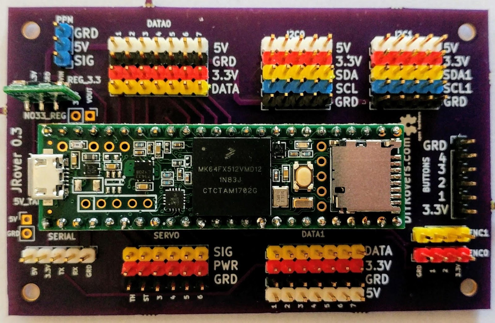
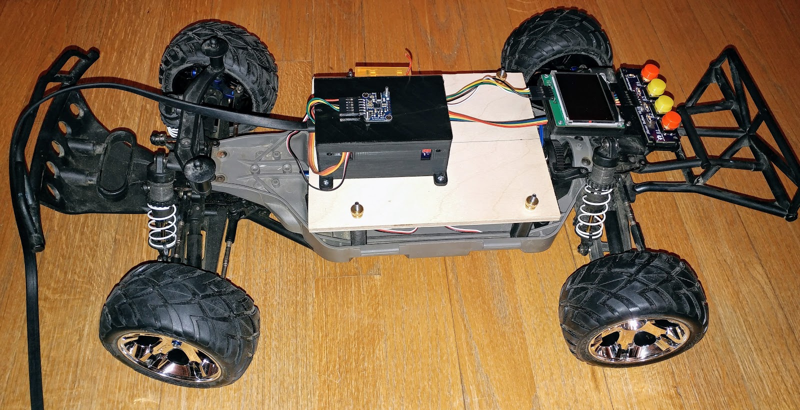
I designed my own carrier board (baseboard) for the Teensy and user input board (button board), because there was a specific set of features I desired. I wanted something simple, with breakouts for the PWM outputs, Serial, IO pins and both I2C buses, so I could separate the IMU from the display. I also wanted an input board with four buttons that was small, with robust mechanical buttons.
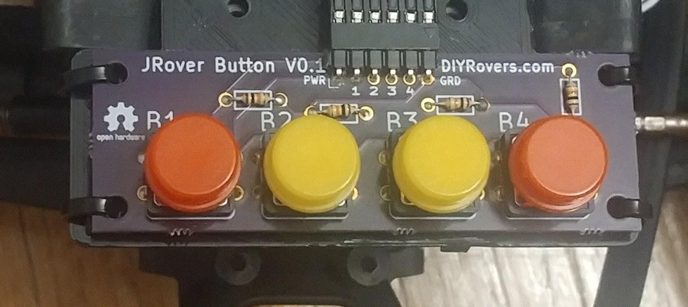
Keep in mind if you use mechanical switches that they can be triggered upon impact with a barrel or other obstacles, so try to shield them. Also, dirt or dust can get into the switches and cause failures, so you might want to have a backup.
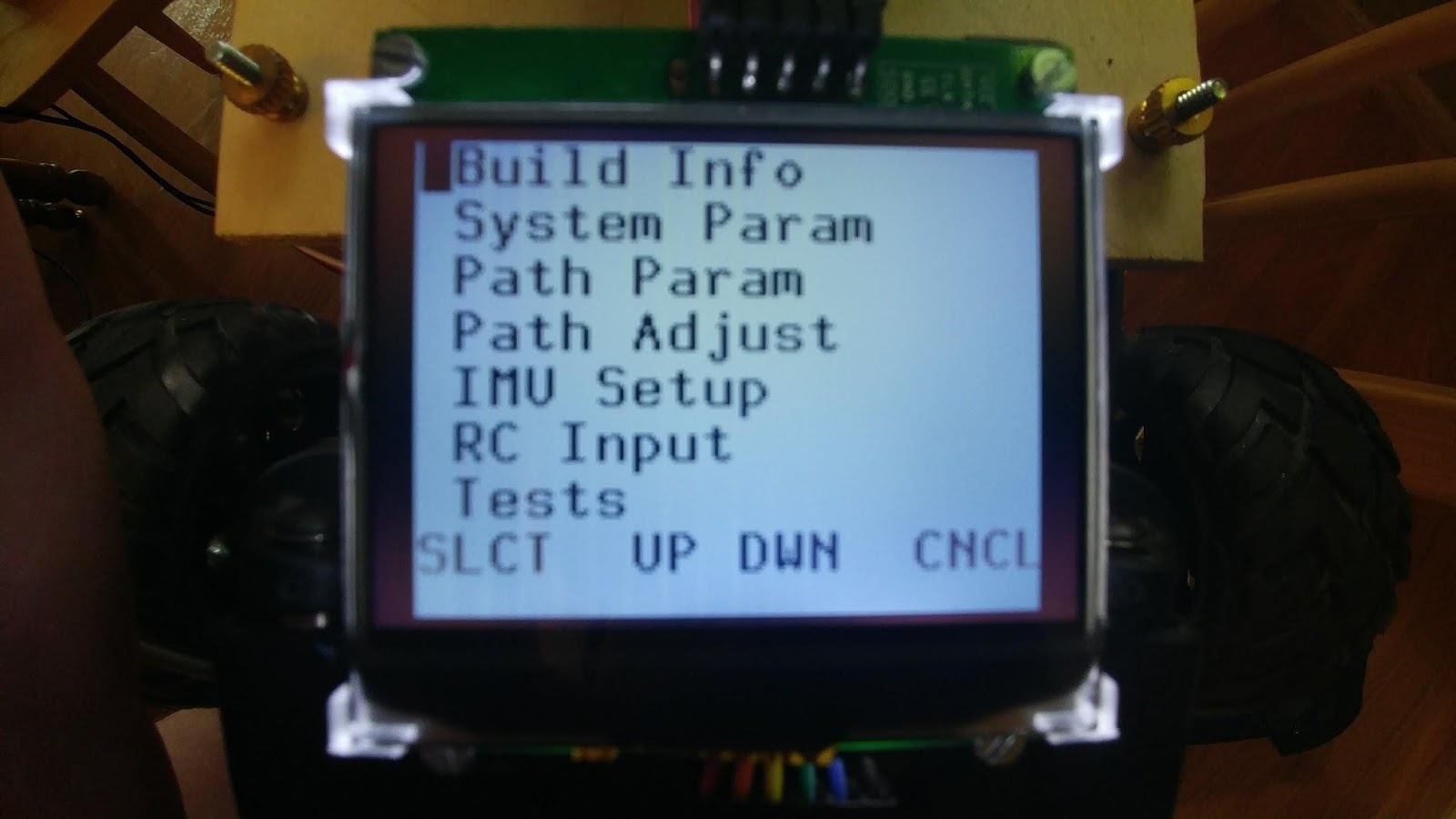
The menu system is crucial for rover control. From this I can run diagnostics, change parameters, record a path or start an autonomous run. A 2-inch LCD Module is used to display this menu. An LCD has improved visibility in direct sunlight compared to an OLED. Two inches is a reasonably-sized display, and I can have eight lines of text on the display, which I find sufficient. The four buttons are used to select and change items as required, and I can also use the RC transmitter for control as well.
I use a standard airplane RC transmitter (TX) and receiver (RX) to send steering and throttle commands to the rover during manual mode, and also for recording waypoints. The baseboard can use standard RC signal Pulse Width Modulation (PWM) or Pulse Position Modulation (PPM) to read commands from the TX. Using a RX with PPM requires only one pin to read six channels, and the code for PPM is part of the Teensy libraries. The extra channels of an airplane-style TX allow for more advanced control of the menu system.
A USB battery pack is connected to the micro USB socket on the Teensy to power the rover. I suggest using a soldered battery rather than loose cells in a holder. Failures I had in the 2014 and 2015 AVCs were caused by loose cells. The micro USB connector on the Teensy is vulnerable, so avoid connecting/disconnecting as much as possible. I used some glue around the micro USB connector to strengthen it, as impacts can cause it to fail.
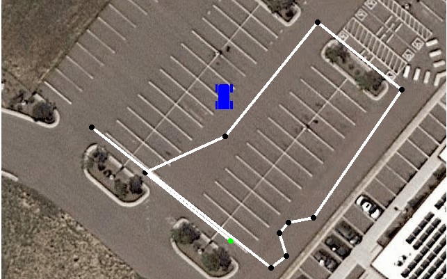
Winning path from 2016 AVC
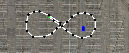
Winning path from 2017 AVC
My rovers uses heading and distance traveled to determine its location. This is a method known as dead reckoning. The pure pursuit algorithm is used to steer the rover. It works by determining how far the rover is off of a direct line between waypoints, and computing a steering angle to put the rover back on the ideal track at a further point down the path.
If you want to build your own rover for AVC here are my recommendations:
- Skip GPS since you can get bonuses for not using it, and GPS isn’t that accurate (typically 3 meters).
- Don’t overthink your design; keep it simple.
- Drive your platform without any autonomous components for several hours. Get a feel for the platform and look for any weaknesses by intentionally hitting the curb a couple times.
- Keep in mind the effects of extra weight and test as much as you can.
- Be prepared for things to fail. Log your failures in a notebook and what you did to correct the issue. If you notice a pattern, don’t be afraid to try something else.
- Have spares for anything you see failing regularly or upgrade to a better part.
I am working on multiple upgrades: bump sensors, a new BNO-080 IMU, LIDAR sensors for obstacle detection, and closed-loop throttle control for speed. I also have several secret upgrades I am working on as well.
If you would like more information about my rovers, or have any questions on building a rover please join DIYRovers. I also started a local chapter of DIY Robocars if you happen to be local to Iowa.
Will you be at the 2018 Sparkfun AVC in September?


We spoke a little in 2016 during practice Friday, I had the red slash that wasn't too successful with GPS guidence. My new design is actually similar to what you're doing, having started up my Teensy 3.5 testing a few weeks ago. I've been looking all over for some kind of encoders and I see you mentioned the Traxxas RPM sensor. Can you pass on some info on where you got this sensor? Thanks! Kelly
Kelly, GPS can be tricky. ;) I'm use the standard Traxxas sensor, part number TRA6520. Black pin = ground, Red Pin = 3.3, and the White pin I've got setup with a weak pull down, and have an interrupt to detect pulses. To make this work you may need change a couple other parts. You'll need to have the telemetry ready parts or get replacements for the stock ones. If you need more help you can contact me through the Google Groups Forum
Thanks for the info. I wasn’t planning on using the temetry receiver. But if you mean the mounting ha4dware, yeah I’ll have to look I to that. I’m also condifering using wall following techniques from my old maze runner days, just follow the hay bales till I get to those darn barrels. :-)
I was just saying older slashes don't have the built in mount for the sensor. So you are on the right track. Wall following. Good idea, but how do you deal with the figure 8?
I use a set of commands that the rover would follow, so something like "follow right wall" with a limiter of something like "until gap detected" or "until forward object detected". Combine with commands like "set speed 10" and once the gap is detected, use a heading command off the compass until the rover sees a side wall again. The encoder or rpm count would be good for knowing when the barrels are coming up and change to some slow speed tactics to navigate around them. Or in your case, lower the battering ram. :-)
Nice write up Jesse and very impressive to win 2 years in a row! Seems to me that maybe Sparkfun should have a practice lap the day before, but then change the actual course for the race. Would force people to use vision/mapping instead of just recording the steering and throttle inputs and "replaying" them for the race. I know they moved the barrels around, but they were so light people just pushed through anyway, maybe fill them with water?
Thanks. I got second in 2015, and that really motivated me. My rover did not push through the barrels last year, it rammed them! LOL. I've given some ideas to the Sparkfun team on how they could change the course to make it harder. Being on a dirt course this year will make replaying challenging and I know two years ago I had some minor issues with the dirt section. I expect the course to continue to get harder over the years, which is why I'm looking at various new technology to do real time mapping and navigation of the course. But I'm not ready to reveal how as of yet. ;)
I love the look of the colored PWM headers! That should make hooking things up that much easier.
Thanks. It certainly does. I got the idea from another Sparkfun competitor, Data Bus. :)
Hi Jesse, nice work and thanks for providing details. I have a few questions if you wouldn't mind sharing. 1) What is the brand and model # of the brushed DC motor that you swapped in? Did you have to make any special modifications to the chassis other than resoldering the wires for the replacement motor? 2) Regarding dead reckoning, was it easy for you to consistently line up the vehicle with the correct initial heading angle? I can imagine if your heading angle is off initially then your trajectory would not be as intended. 3) Now that Sparkfun AVC is retired, do you plan to participate in any other competitions in the future?
Thanks!! 1) Motor is a RC4WD 540 motor with 35 turns. No changes needed, any 540 motor should be able to slot into place without much issues. I'm using a Castle ESC and it can work with brushed and brushless motors with just a setting change. 2) It is a trick/practice to learn how to set the same initial angle. When I'm testing I use cracks/cuts in the pavement to line it up. For AVC I would use the sections of the start/finish line itself. There was an assumption that this would not move. Which for at least one year was not the case, but other competitors noticed and brought it up and it was moved back. I have looked at using compass to get the initial angle, but the accuracy is never been there. Less error by ignoring the compass. 3) I'm working on a new "speed" rover and plan to compete with the local RC guys for now, and try to beat them at least on time for now, then I'll try to beat them in a race after that. But I expect this to take a couple years to get there. I'm hoping to organize a Midwest/Iowa AVC for some future date. I have monthly meeting of "DIYRobocars" to get more interest locally, but not made a lot of progress yet. I've got other projects I'm working on as well, and you will hear more about them soon.;)
Surprised there is still a way to be competitive with such a simple design, this many years into the competition. The Traxxas RPM sensor senses only the output shaft of the motor. Wheel slippage & differential gearing should make it highly inaccurate.
Understood, but with a differential you would need sensors at each drive wheel, since they will spin at different rates.
I modified the rpm sensor setup so I now get 3 pulses per revolution instead of one. Wheel slip isn't an issue if you go slow enough, and there is no issue with the differential gear. The front/rear differential are just gear reductions, and there is no slippage in them. They actually help with a gear reduction to increase encoder resolution. I removed the slipper clutch, so in the whole drive train there is no slip. I think the results speak for themselves. Over a Sparkfun sized course my error is often a foot or less. The dirt track this year will be the biggest variable, so I am working on ideas to counter slippage.
how's this for accuracy?