Perfect Parking with LiDAR
It's time to bounce that old tennis ball out of your garage, and up your game with this simple project that lets you know exactly where to stop when pulling in to your garage.

Distance sensors are great! They're generally a maker's first step towards creating a basic autonomous robot, but did you know that there are many other uses for them? It's true! Everything from Halloween props to annoying musical instruments to parking garage guidance systems can be made using distance sensors. So let's take ours off the workbench and out into the wild, and make something happen!
First, find a need
I've never had a tennis ball, boogie board or anything else hanging from my garage ceiling to let me know exactly when I should stop my car when pulling into the garage. However, now that I have a teenager who's about to start driving, I think maybe it's time. Now, I don't play tennis, but I do play electronics, so I'm going to use what I have available to me. My plan is to use a distance sensor and create a small stop light. When the car first pulls into the garage, a green LED will be illuminated. As the car gets closer, a yellow LED will light up, and when the car gets to the ideal stopping point, the driver will see a red LED. I'll design and 3D print a simple traffic light to use as the housing, so it will be aesthetically pleasing, too!

A quick demo to show off the new TFMini Stop Light (vehicle not to scale).
So, which distance sensor is right?
Gotta Get 'Em All! (I know, I know, but the actual phrase is trademarked).
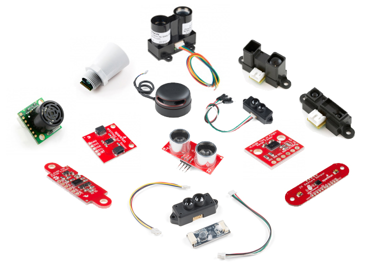
With so many distance/proximity sensors to choose from, how do you know which one is right for your project? There are a number of considerations, such as range, resolution, interface type, update rate and cost. Sometimes, you may need to decide which options have some flex (does it really need to update 635 times per second?), and which ones are must-haves (my professor said we have to use I2C components). My garage measures about twenty-six feet from the back wall to the garage door. While I could probably get away with one of our XL-MaxSonar Ultrasonic units, which are good up to about twenty five feet, for this build, I'm going to go with the TFMini - Micro LiDAR Module.
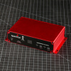
I'm using it with the Qwiic package, as that includes a boost board. Since the TFMini runs on 5V but communicates at 3.3V, the boost board that comes with the Qwiic package eliminates the need for logic level conversion if using a 5V board, or a split power supply if using a 3.3V board. By pairing this with the Sparkfun Blackboard, which has a built-in Qwiic connector, I can make the sensor half of this hookup a straightfoward plug and play design. Add a few Super Bright LEDs, resistors and a power supply, and we're good to go!
Here's the parts list for this project.
Turning parts and code into a thing
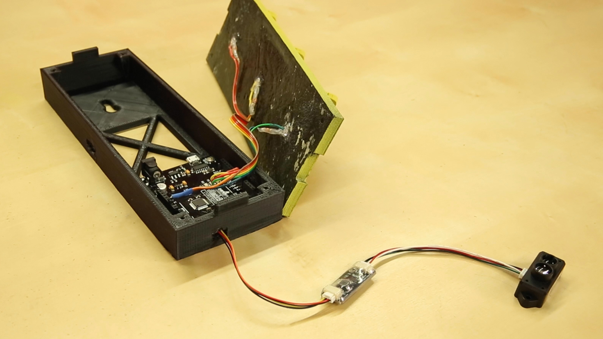
Easy to put together, and using a little ribbon cable keeps it tidy
The Qwiic system really makes this build pretty simple. The TFMini Qwiic version comes with the boost board and a pair of cables. One cable runs from the module to the boost board, and the other from the boost board to the Qwiic connector on your Blackboard. The green, yellow and red LEDs run to pins 8, 9 and 10, respectively. For the code, I simply did a little tweaking to the LidarTest.ino sketch you can find on the TFMini Qwiic's Hookup Guide. Here's how it looks:
/*
  TFMiniStopLight.ino
  Rob Reynolds, November 19, 2018

  This code is a small practical demonstration application
  of the TFMini Lidar Module. The 3D files can be found in
  the Github repository, here [ https://github.com/ThingsRobMade/TFMini_Stop_Light ]
  Based heavily on the previous collaborative work done by
  Nate Seidle and Benewake. The original example sketch for
  the Qwiic Enabled TFMini can be found here:
  (https://www.sparkfun.com/products/14786)

  This code is free, but if you find it useful, and we meet someday, you can buy me a beer (Beerware license).

*/

#include <Wire.h>

uint16_t distance = 0; //distance
uint16_t strength = 0; // signal strength
uint8_t rangeType = 0; //range scale
/*Value range:
  00 (short distance)
  03 (intermediate distance)
  07 (long distance) */

boolean valid_data = false; //ignore invalid ranging data

const byte sensor1 = 0x10; //TFMini I2C Address

// Define pins for LEDs
const int greenLED = 8;
const int yellowLED = 9;
const int redLED = 10;
int stopLimit = 160; //Change this number of cm to adjust stop distance

void setup()
{
  Wire.begin();

  Serial.begin(115200);
  Serial.println("TFMini I2C Test"); //For testing using Serial Monitor

  // Set LED pins as outputs
  pinMode(redLED, OUTPUT);
  pinMode(yellowLED, OUTPUT);
  pinMode(greenLED, OUTPUT);
}

void loop()
{
  if (readDistance(sensor1) == true)
  {
    if (valid_data == true) {
      Serial.print("\stopLimit["); //These Serial.print lines remain for testing and adjustment purposes
      Serial.print(stopLimit);
      Serial.print("\tDist[");
      Serial.print(distance);
      Serial.println();

      if (distance <= stopLimit) {
        digitalWrite(redLED, HIGH);
        digitalWrite(yellowLED, LOW);
        digitalWrite(greenLED, LOW);
      }
      else if (distance > stopLimit && distance < (stopLimit + 200) ) { //change this number to increase     distance yellow stays lit
        digitalWrite(redLED, LOW);
    digitalWrite(yellowLED, HIGH);
    digitalWrite(greenLED, LOW);
  }
  else if (distance > (stopLimit + 199) ) { //change this number to adjust when yellow LED illuminates
    digitalWrite(redLED, LOW);
    digitalWrite(yellowLED, LOW);
    digitalWrite(greenLED, HIGH);
  }
}

//  else {
//   Serial.println("Read fail");
//  }

delay(50); //Delay small amount between readings
  }
}


//Write two bytes to a spot
boolean readDistance(uint8_t deviceAddress)
{
  Wire.beginTransmission(deviceAddress);
  Wire.write(0x01); //MSB
  Wire.write(0x02); //LSB
  Wire.write(7); //Data length: 7 bytes for distance data
  if (Wire.endTransmission(false) != 0) {
    return (false); //Sensor did not ACK
  }
  Wire.requestFrom(deviceAddress, (uint8_t)7); //Ask for 7 bytes

  if (Wire.available())
  {
    for (uint8_t x = 0 ; x < 7 ; x++)
    {
      uint8_t incoming = Wire.read();

  if (x == 0)
  {
    //Trigger done
    if (incoming == 0x00)
    {
      //Serial.print("Data not valid: ");//for debugging
      valid_data = false;
      //return(false);
    }
    else if (incoming == 0x01)
    {
      Serial.print("Data valid:     ");
      valid_data = true;
    }
  }
  else if (x == 2)
    distance = incoming; //LSB of the distance value "Dist_L"
  else if (x == 3)
    distance |= incoming << 8; //MSB of the distance value "Dist_H"
  else if (x == 4)
    strength = incoming; //LSB of signal strength value
  else if (x == 5)
    strength |= incoming << 8; //MSB of signal strength value
  else if (x == 6)
    rangeType = incoming; //range scale
}
  }
  else
  {
    Serial.println("No wire data avail");
    return (false);
  }

  return (true);
}
I also did a quick stop light model, and you can download that from the Github repository here.
GOTCHA WARNING! Because of the power needs of the TFMini, and the power management system on the SparkFun Blackboard, if you try to run your final project with a power supply using the barrel jack, it will freeze up, the green LED will remain illuminated, and your driver, basing their actions solely on your sweet new project, will drive right into the wall. However, powering it through the microUSB connector works without issue. So even though that big beautiful barrel jack is staring right at you, tempting you, don't give in! It will only lead to misery.
See the completed build here, in action!
Now make it your own!
This build is about as quick and basic as they come, but it doesn't have to be. You've got the code, you've got the .STL files, now take them and run with them. Add some buttons to make it easier to adjust the optimal stopping distance. Create a better housing. Increase the number of LEDs to make it more visible. If you're feeling really ambitious, you might even swap out the Blackboard for a Raspberry Pi, and program this project in Python. Is there any advantage to using an SBC over a microcontroller for this project? Absolutely not. But why just kill a project when you can overkill it? Happy Hacking, friends!
Interested in learning more about distance sensing?
Learn all about the different technologies distance sensors use and which products would work best for your next project.
Take me there!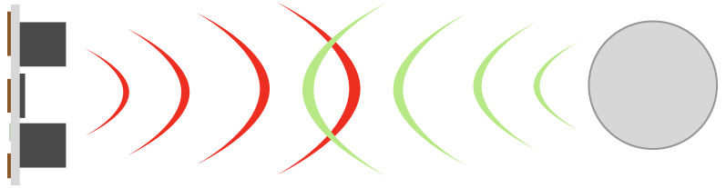


One advantage of a tennis ball - it doesn't require a backup poweer supply. Since all garage door openers are required (at least in the U.S.) to have "releases" so the door can be opened when the power fails, it would seem wise to have a system that will still work in the event of power failure, or in the event of a run of cloudy days if you go with solar power. (Also, in defense of the tennis ball: it won't be ruined if it happens to get wet!)
I'd suggest an improvement to the code (I've been working with computers since shortly after Neil Armstrong took his "one small step"):
then later in the code
and still later
Anyway, Rob, great project! (And good luck with your young driver!)
Two more thoughts about the code: using a "#define STOP_LIMIT 160" rather than having stopLimit as a variable would help preserve RAM (although for this program it's no big deal, but I have done Arduino programs where I ran out of RAM), or using "const int stopLimit=160;" at least gets the compiler to (try to) keep your code from "accidentally" changing the value.
By the way, I like the "Beer License"!
(And I hope that everyone realizes I'm NOT attacking, but trying to offer constructive suggestions for "good practices".)
Thank you for that, and it absolutely doesn't feel like an attack at all. With most projects I do, even once it's up and running, I always feel like improvements could be made to my code. (That's especially true when pushing to meet a deadline, as is the case with every one of my posts.) If I recall, I think I kept stopLimit as a variable in case I had time to add a stopLImit Up and stopLimit Down button as inputs to more easily adjust that distance for the user. But if the user is a maker who's going to be putting it all together themselves, they could just as easily change the #define STOP_LIMIT number within their own code. Thanks for the feedback!
If I recall correctly, the Blackboard has a few bytes of "user accessible" EEPROM. It seems to me that if you included the "stopLimit Up" and "stopLimit Down", storing the value in EEPROM would be an ideal use of the EEPROM. (I'd be inclined to read one pin in setup(), and if it's grounded, then use a "default" value for stopLimit and write that to EEPROM, otherwise read the value from EEPROM and maybe if it's zero, use the "default" value. If the stopLimit gets adjusted, write it to EEPROM whenever it does get adjusted.)
Side note: the ambitious maker could also do the same sort of thing for "yellowLimit" (instead of my aforementioned YELLOW_LIMIT constant), having "yellowLimit Up" and "yellowLimit Down" buttons.
Sorry... I spent too many years as an Engineer who always looking for easy-to-implement "features" to make Marketing happy... especially ones that don't need much additional hardware!
Would it make sense to turn off the LEDs after a minute or so?
Absolutely! If I had ten more minutes before this was due, that would have been the first addition I would have made to the code.
i am in the early stages of building an automated dustbin, whose lid opens automatically once it senses footsteps approaching kindly let me the right sensors to use , i am based in Kenya.
Woow Its pretty amazing the design, and I love the whole project. Are you going to keep posting articles like this? Would love to see more of them
Glad you like it! The plan is to continue to take our components, and build them into practical projects like this. Hopefully it can inspire people to come up with ideas of what they can create next, once they've mastered the basics.
A non-software solution to adding the "sleep" feature is to plug the power supply into the light socket on the garage door opener. Most openers have lights that turn on when the door is opened and turn off a minute or so after use.
Great project!
It would make sense to me to have a potentiometer that the user can adjust to set the stopping distances.
Also on that note, you can get a finer idea of placement by having two (or more) lights lit sometimes. For instance, you can have the transition pattern be something similar to the table below. (Distances can be set by hard-coded values or by potentiometers)