Let's talk about Eagle Configuration Scripts: how to use them, and why using your own can make your Eagle experience more enjoyable and efficient.
Let me preface this by saying that there is more I do not know about Autodesk's EAGLE PCB Design Software than there is that I do. That said, this is just a quick explainer, and there will be plenty left unsaid about using Eagle scripts.
If you are new to Eagle or unfamiliar entirely, check out these tutorials to help you get started:
What is a Configuration Script?
Put simply, it's a file used to configure an instance of Eagle with specific settings when opened.
When an instance of an Eagle editor is opened, Eagle accesses a configuration script file (eagle.scr). The configuration script contains a series of commands written in human readable text that change the settings for any instance of an Eagle editor workspace when opened. These include: BOARD Editor, SCHEMATIC Editor, LIBRARY Editor, DEVICE Editor, PACKAGE Editor and SYMBOL Editor. By changing the set of commands within the configuration script, the user can customize the settings of any of the aforementioned Eagle editors without the tedium of having to manually change the settings every time you open up an instance of Eagle.
Perhaps the most valuable feature of a personalized configuration script is the ability to setup a hotkey assignment map and workspace that caters to how you use Eagle. Whether you are designing schematics, designing boards, designing both or just reviewing designs, you can tailor the configuration of Eagle to allow you to work more efficiently.
Eagle is distributed with a default configuration script; it sets some default layers to be used, sets the unit(s) of measure, sets the grid spacing and calls some .ulp files, plus a few more things. Check it out below:
# Configuration Script
#
# This file can be used to configure the editor windows.
#
# Uncomment this if you want a set of useful default shortcuts!
#SCRIPT default-assign.scr;
#

BRD:
MENU '[bin/designlink.svg] Search and order : Run designlink-order.ulp -general;'\
    '[bin/pcb-service.svg] PCB Service : Run pcb-service.ulp;'\
;
DISPLAY = 'Preset_Top' None 1 17 18 19 20 21 23 25 39 41 51;
DISPLAY = 'Preset_Bottom' None 16 17 18 19 20 22 24 26 40 42 52;
DISPLAY = 'Preset_Standard' None 1 2 3 4 5 6 7 8 9 10 11 12 13 14 15 16 17 18 19 20 21 22 23 24 25     26 39 40 41 42 51 52;

SCH:
Grid Default;
Change Width 0.006in;
MENU '[bin/designlink.svg] Search and order {\
                                          General : Run designlink-order.ulp -general; |\
                                         Schematic : Run designlink-order.ulp; \
                                         }'\
     '[bin/LTspice.svg] LT Spice simulation {\
                    Export: RUN ltspice.ulp /E; |\
                    Export Setup: RUN ltspice.ulp /E /S; |\
                    Export Group: RUN ltspice.ulp /E /G; |\
                    Import: RUN ltspice.ulp /I; \
     }' \
;

LBR:
MENU '[bin/designlink.svg] Search and order : Run designlink-order.ulp -general;'\
     '[bin/LTspice.svg] LT Spice simulation {\
                  Export: RUN ltspice.ulp /E; |\
                  Import: RUN ltspice.ulp /I; \
     }'\
     '[bin/pads-pcb.svg] PADS package import : RUN import-pads-powerpcb-v5;' \
;

DEV:
Grid Default;
MENU '[bin/designlink.svg] Search and order : Run designlink-order.ulp -general;' \
     '[bin/LTspice.svg] LT Spice simulation {\
                  Export: RUN ltspice.ulp /E; |\
                  SpiceOrder : RUN spiceorder.ulp; |\
                  SpiceModel: ATTRIBUTE SPICEMODEL |\
                  Value2: ATTRIBUTE VALUE2 |\
                  Import: RUN ltspice.ulp /I; \
     }'\
     '[bin/pads-pcb.svg] PADS package import : RUN import-pads-powerpcb-v5;'\
;

SYM:
Grid Default On;
Change Width 0.010in;
MENU '[bin/LTspice.svg] LT Spice simulation {\
                  Export: RUN ltspice.ulp /E; |\
                 SpiceOrder : RUN spiceorder.ulp; |\
                 Import: RUN ltspice.ulp /I; \
    }'\
;

PAC:
Grid Default On;
Change Width 0.005in;
Change Size 0.050in;
MENU '[bin/LTspice.svg] LT Spice simulation {\
                  Import: RUN ltspice.ulp /I; \
     }'\
     '[bin/pads-pcb.svg] PADS package import : RUN import-pads-powerpcb-v5;' \
     ;
This default Eagle configuration script by no means makes Eagle unusable, but you are stuck with some pretty basic configuration settings. We have a SparkFun Eagle Settings GitHub repository, which includes an Eagle configuration script that provides a good starting point for understanding how these scripts are used, and for personalizing your own.
If you are new to GitHub, below are a couple tutorials explaining what it is, and how it is used:
Below is a simple demo configuration script to use as an example. Let's quickly break down some of the script so that you can get started making or modifying your own!
# Demo Startup Configuration Script
# This file is used to configure the editor windows.

##############GLOBAL Instructions##############
#Assign GLOBAL workspace specific hotkeys
Assign F7 'NAME';

##############BOARD EDITOR specific Instructions##############
BRD:
#Assign BRD workspace specific hotkeys
Assign F7 'MOVE';

#Setup Grid
Grid inch 0.05 on;
Grid alt inch 0.005;

#changes background color of board to black
SET PALETTE BLACK;

#add layers
LAYER 227 xtra_ref;

#Layer colors
#Set top layer to dark red
Set color_layer 1 4;
#Set xtra_ref layer to blue-green
Set color_layer 227 11;

# When opening, hide all layers, then show layers 1 2 15 16 17 18 19 20 21 22 23 24 45 51 227 228 229 230 231
display none; display 1 2 15 16 17 18 19 20 21 22 23 24 45 51 227 228 229 230 231;

#Assign BRD workspace specific hotkeys
Assign F8 'move';


##############SCHEMATIC EDITOR specific Instructions##############
SCH:

#Assign SCH workspace specific hotkeys
Assign F9 'Net';

#net definitions
CLASS 1 8_mil 8mil;
CLASS 2 10_mil 10mil;
CLASS 3 12_mil 12mil;
CLASS 4 15_mil 15mil;
CLASS 5 20_mil 20mil;
CLASS 6 25_mil 25mil;
CLASS 7 30_mil 30mil;


##############LIBRARY EDITOR specific Instructions##############
LBR:

#Assign LBR workspace specific hotkeys
Assign F10 'Grid inch 0.05 on; Grid alt inch 0.0001;';

#Set LBR workspace specific grid sizing
Grid mm 1 on;
Grid alt mm 0.1;

##############DEVICE EDITOR specific Instructions##############
DEV:

Grid Default;

##############SYMBOL EDITOR specific Instructions##############
SYM:

Grid Default On;
Change Width 0.010;

##############PACKAGE EDITOR specific Instructions##############
PAC:

Grid Default On;
Change Width 0.005;
Anatomy of a Configuration Script
The configuration script is broken into a section for each variation of an Eagle editor, and each type is denoted by an editor-specific label. These labels instruct Eagle to run only the portion of the script that is between the editor type label being opened and the next editor label. This means the user can customize unique configuration settings for each editor type, most importantly hotkeys.
Eagle Editor Script Labels
| Editor Type | Editor Label |
| Schematic | SCH: |
| Board | BRD: |
| Library | LBR: |
| Device | DEV: |
| Symbol | SYM: |
| Package | PAC: |
The portion of the script that lies above all labels is considered global. These instructions will run for any editor type opened, and will run before the instructions under the editor-specific label are run. Instructions under an editor label will supersede any global instructions that were run prior to the editor label.
To add a comment to your script, insert a pound symbol (#) followed by the text for your comment. Each new line of comments will require a new preceding pound symbol. A comment can live on the same line as a command, assuming it is stated after the command.
Eagle Commands
Eagle utilizes a built-in set of text commands that tell it to do anything from setting a layer's color to setting default wire widths. These commands can be used in place of any of the toolbar buttons, and the command structure and syntax is standardized within Eagle. Conviniently, the commands that can be entered into the command line field of an editor workspace are identical to those that are used to populate an Eagle configuration script.
- As a side note - To utilize a command in a workspace, simply enter the command into the Eagle command line field with proper syntax and press enter. It should be said that some commands are specific to a certain type of editor, for example, a command specific to the schematic editor may return an error if entered into the command line of a board editor. This is also true of commands in a configuration script.
Lets look at a basic Eagle command used under the BRD: label in the above demo configuration script, and discuss the syntax and function. Checkout the command:
Grid inch 0.05 on;
This command tells Eagle to configure three settings:
- inch - sets the unit of measure to be used for the grid to inches
- 0.05 - sets the grid spacing to 0.05 units
- on - sets the grid to be visible to the user
The command is "Grid," and the parameters are: "inch," "0.05" and "on." The semi-colon ";" tells Eagle that there are no more parameters. Remember, this command lives under the BRD: label, which dictates that this command will only be used when opening an instance of the board editor.
You can easily chain together parameters for one command by listing them separated by a space, and terminating the command by adding the semi-colon at the end. Here's another example:
DISPLAY 1 16 17 18 19;
This tells Eagle to make layers 1, 16, 17, 18 and 19 visible to the user. It's pretty intuitive. Interestingly, one could design an entire schematic with a string of text using Eagle's built-in commands.
Writing and Editing a Configuration Script
Eagle contains a built-in text editor that can be used for writing/editing SCRIPT and ULP files, but you can use any text editor that allows you to choose the file extension when saving your file. Eagle script files have a .scr file extension, which can create an issue when using Windows and an external text editor. Windows views a .scr file as a screensaver file, which means users may have trouble opening this file with a text editor. To fix this, go into the default apps setting menu (WINDOWS 10) or Program settings (WINDOWS 7) and set the default app for .scr files to whichever text editor you prefer.
Another point to take note of is that the configuration script file must be named "eagle.scr", and must live in the directory that is specified in the Directories: Scripts field.
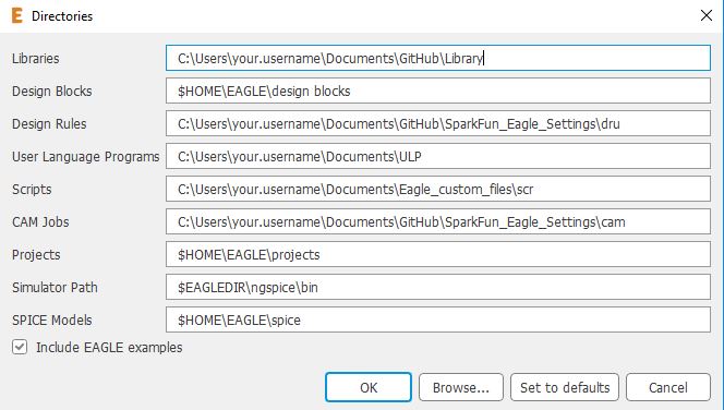
Setting the Directory for your Configuration Script
To change/set any of the directory paths that Eagle uses to look for files, open up an instance of the Eagle Control panel, click on Options in the menu bar and click once more on Directories... in the drop-down. This will open the directories window, which houses the fields to set the file paths to the directories that contain files that you and Eagle want to use together. The Scripts field is where you set your configuration script file path.
For a detailed list of built-in Eagle commands, command descriptions and command usage examples, check out the Editor Commands section of the Eagle help utility, and for more information about Eagle scripts, check out the SCRIPT sub-section of the the Editor Commands section.
Eagle has a great built in HELP utility; it's an invaluable resource for novice and expert users alike. The HELP utility can be found on the far right of the menu bar on any main Eagle workspace window or the Eagle Control Panel.
Now go create your own Configuration Script!!!
...and be sure to let us know about your experiences using Eagle configuration scripts, plus any of your own tricks and tips, in the comments below.


One of the things I have in my startup script is several menu buttons for the Board layout screen. These buttons select what layers to display, so I can see only the top, only the bottom, a fab drawing view, or back to 2,4, or 6 layer views.
MENU 'Top: script DisplayTop.scr;'\
'Bottom: script DisplayBottom.scr;'\
'2: script LayersLayout2.scr;'\
'4: script LayersLayout4.scr;'\
'6: script LayersLayout6.scr;'\
'Fab: script LayersFab.scr;'\
And then a typical script like DisplayTop would be
show only the topside elements
Display NONE 16 17 18 20 22 24 26 34 36 38 40 42
In glancing over this, it looks like another good tutorial from Sparkfun. The Sparkfun tutorials were invaluable when an employer insisted upon my [being ab]use[d by] Buzzard, er, Eagle, several years ago. Frankly, I found Eagle to be one of the least-user-friendly, most counter-intuitive programs (of any type) I've used -- and I've used a lot of programs in the (soon to be) past half century. (The one that takes the cake for "worst" was a so-called "smart" thermostat, where if you made an error in programming it, you'd have to start over from scratch.)
I find KiCad and gEDA far more "intuitive" and easier to use, though, according to the Wikipedia entry, gEDA's latest stable version is dated Sept. 25, 2013. (I'll admit that it's been a couple oof years since I've used either of them.)
I've tinkered a little with Fritzing, which can make "circuit diagrams" that are easier for the beginner to understand than the normal schematic, but the time or two I tried to use it for a PCB layout, I was, well, underwhelmed by it. (Agein, that was several years ago, and it might have improved.
Another thing to keep in mind is that the "free" version of Eagle is limited to two-layer boards of no more than 80sq-cm (for example, a little over 3 inches by 4 inches), whereas neither KiCad nor gEDA have these limitations (and are free).
BTW, I learned long ago (the hard way) to "trust but verify" when using parts libraries for any CAD software -- I discovered that the reason one prototype board wasn't working was because the library had the wrong pinout for the venerable 2N2222 transistor! (I got the board to work, but the transistor looked like it desperately needed the restroom... ;-) (Be sure to check hole sizes as well as pin-outs -- I've had to rev boards for that, too!)
Nice write up Eric. Thanks! The creation of an extra reference layer will come in handy!
Here are couple of my favorite commands:
use -*;
This will clear your design from using all libraries. After running this command, then I will usually run the command "use" again, which will open the library manager, and then I can find the libraries I want to use (usually only the SparkFun Eagle Libraries).
ripup @;
This will rip up (aka un-pour) your polygons. Useful, when you are routing and removing the solid pours can make it a bit easier to see your traces.
Thanks again!
Not sure how the ripup @; command would be used with a startup script, since the pours aren't filled when you open a brd file. But I love the fact that this will un-pour on command. I've always moved the polygon lines around to do the same thing, very clumsy. I would go as far as to add this command to a menu button, like I did in my example. Very cool!