If you are like me, you enjoy the charm of driving an older vehicle. The mechanical feedback from the car is more organic. You aren’t surrounded by safety and driver aid systems that jump at the opportunity to correct your oh-so human actions. These cars were born in an era when manufacturers strove to have their own look. Shoot, you still get to plug the key into the ignition! You get the point, but as much as the above is appealing, there are many shortcomings in older vehicles, one of the primary being security.
Nowadays, most cars come with keyless ignition systems as standard equipment. This technology has been used in the industry since the late nineties in high-end automobiles, and only in the last decade or so has this system made its way to the masses. These systems can certainly come with their own set of headaches, but they do make auto theft much more difficult when using less tech-savvy methods.
My goal here is to create a keycode-based security system for starting my 80’s-era soon-to-be daily driver.
Disclaimer: the motor for said daily driver is still not actually in the car, so installation of this system will be covered in a future post. This system is designed to function with a starter circuit found in a 1980’s-era Volvo.
The primary motivations behind installing this system are to disable the ability to start the vehicle without entering the proper keycode, and to make the act of “hot-wiring” the vehicle much more difficult. The intention is to be as non-invasive as possible, so this system does not require the removal of any OEM parts included in my vehicle’s starting circuit.
Concept
The photo below illustrates the concept. Lets walk through it and talk about some reasoning.
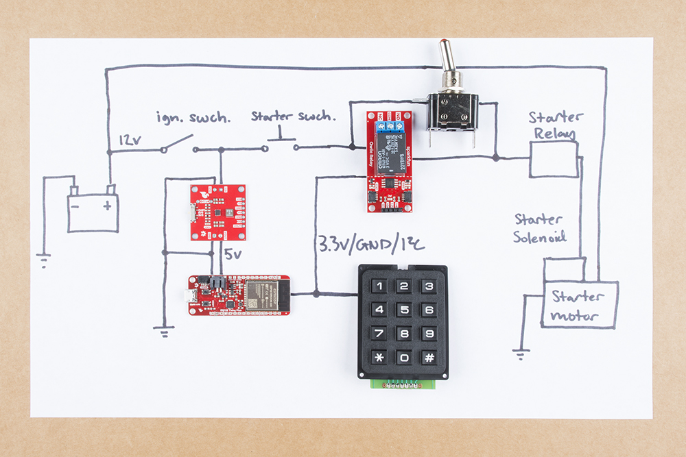
In this basic implementation I am using the car battery to supply power to my microcontroller. In this case I’m opting to use the Sparkfun Thing Plus – ESP32 WROOM . I chose this board because of its potential – most basic microcontroller boards could perform the task needed, but I want to keep adding features and capabilities to this system, and the wireless and battery capabilities offer a lot of feature expansion. If I were simply installing the system depicted in the picture without the intention of adding to it, I might have opted for the less expensive Arduino Pro Mini.
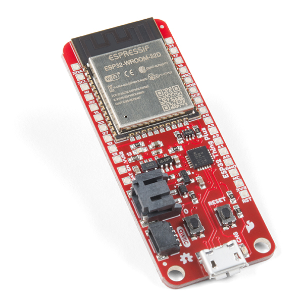
Power is supplied to the microcontroller after the ignition switch, which, if functioning properly, should prevent the board from being powered up when the ignition switch is in the OFF position. This will keep the microcontroller from draining the car battery while the car is not in use and the battery is not being charged by the alternator. In the future, the onboard JST and LiPo charger of the Sparkfun Thing Plus could come in handy.
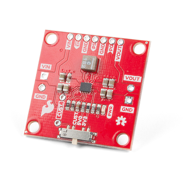
Now, I can’t just supply my Sparkfun Thing Plus with 12V from the ignition, so I’m using the Sparkfun Buck-Boost Converter to regulate that voltage down to 5V, which will then be routed to the Sparkfun Thing Plus’s VUSB pin. I will likely be placing a 1A or 500mA fuse between the 12V supply of the ignition and the Buck-Boost board. This should protect my ignition circuit in the chance that something I have added shorts.
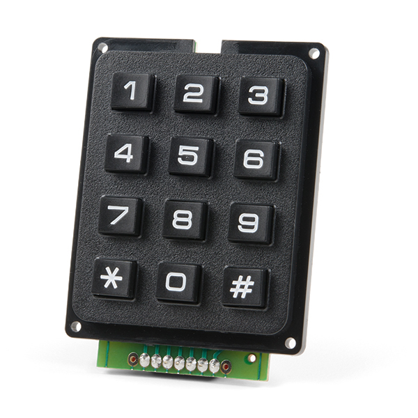
From there I am utilizing the Sparkfun Qwiic Keypad – 12 Button as my HID device. This will live in the cabin of the car and will be used to enter the keycode. I’m connecting the keypad to my Thing Plus with a 100mm Qwiic Cable.
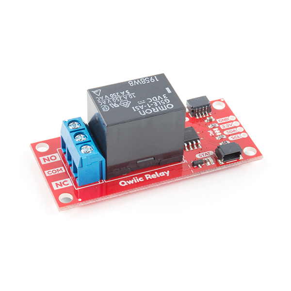
The next and most integral component is the Sparkfun Qwiic Single Relay. This board uses a ATTiny85 to act as an I2C slave and controls the the relay, allowing the user to open and close the relay using I2C communication. The Qwiic Relay will be acting as another switch on the starter solenoid power cable running from the ignition switch to the starter solenoid. When the relay is open, it should prevent current from reaching the starter solenoid. By controlling the current path to the starter solenoid, I can prevent the starter from engaging, and thus prevent the car from being started (in most cases).
Because this component will be under the hood, I opted to use some 22AWG wire to connect my Thing Plus to the Qwiic Relay. I will likely end up using some heat shielding on the wires and an enclosure for the Qwiic Relay to protect the parts from the heat of the engine bay and the elements.
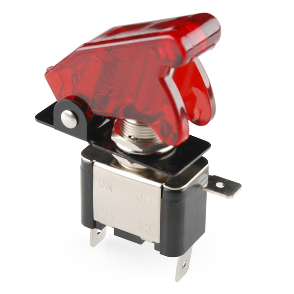
I also want to include an option to bypass the Qwiic Relay. To do this, I’m going to use this toggle switch rated for 20A and 12V, which will be wired up in parallel with the Qwiic Relay on the starter solenoid control line.
Placing both the Qwiic Relay and the toggle switch under the hood should make hot-wiring the car much more difficult, requiring the would-be thief to go under the hood to reconnect the starter solenoid control line. Or just flip the switch... if they can find it.
At this point, it’s worth mentioning that I will be using at least 8AWG stranded wire to connect the Qwiic Relay and the toggle switch to the starter solenoid control line. This gauge of wire is large enough to safely handle the current of the starter solenoid control line, and should be available at any automotive parts store.
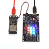
Mini DEMO
Above is a demo using a RedBoard Qwiic and a Qwiic Keypad to successfully close the Qwiic Relay when the proper keycode is entered. In this case the code is “1234.”
Below is the sketch I am using in the demo above:
#include <Wire.h>
#include "SparkFun_Qwiic_Keypad_Arduino_Library.h"

#define COMMAND_RELAY_OFF     0x00
#define COMMAND_RELAY_ON      0x01

const byte qwiicRelayAddress = 0x18;     //Default Address

KEYPAD keypad1; //Create instance of this object

const char keyCode[] = {'1','2','3','4'};  //enter code here

char userEntry[] = {0, 0, 0, 0}; // used to store the presses coming in from user
boolean userIsActive = false; // used to know when a user is active and therefore we want to engage timeout stuff

#define TIMEOUT 30 // 100s of milliseconds, used to reset input. 30 equates to 3 second.
byte timeOutCounter = 0; // variable this is incremented to keep track of timeouts.

byte userEntryIndex = 0; // used to keep track of where we are in the userEntry, incremented on each press, reset on timeout.

#define stat_LED 13

void setup() {

  Serial.begin(9600);

  Wire.begin(); // join the I2C Bus

  if (keypad1.begin() == false)   // Note, using begin() like this will use default I2C address, 0x4B.
                  // You can pass begin() a different address like so: keypad1.begin(Wire, 0x4A).
  {
    Serial.println("Keypad does not appear to be connected. Please check wiring. Freezing...");
    while (1);
  }

  testForRelayConnectivity();
  relayOff();

  pinMode(stat_LED,OUTPUT);
  digitalWrite(stat_LED, HIGH);
  delay(250);
  digitalWrite(stat_LED, LOW);

  Serial.println("Car Starter ready for operation!");
  Serial.println("Keypad Car Starter Menu:");

}

void loop(void)
{

  keypad1.updateFIFO();  // necessary for keypad to pull button from stack to readable register
  char button = keypad1.getButton();

  if (button == -1)
  {
    Serial.println("No keypad detected");
    delay(1000);
  }
  else if (button != 0)
  {
    //Serial.print(button);
    userEntry[userEntryIndex] = button; // store button into next spot in array, note, index is incremented later
    printEntry();
    userIsActive = true; // used to only timeout when user is active
    if (checkEntry() == true)
    {
      relayOn();
      digitalWrite(stat_LED, HIGH);
      Serial.println("\n\r\n\rReady to start!");
      clearEntry();
      userIsActive = false; // don't display timeout stuff.
      delay(1000);
      digitalWrite(stat_LED,LOW);
    }
    userEntryIndex++;
    if ( userEntryIndex == sizeof(keyCode)) userEntryIndex = 0; // reset
    timeOutCounter = 0; // reset with any new presses.
  }

  delay(100); //10 is good, more is better, note this effects total timeout time

  timeOutCounter++;

  if ((timeOutCounter == TIMEOUT) && (userIsActive == true)) // this means the user is actively inputing
  {
    Serial.println("\n\r\n\rTimed out... try again.");
    timeOutCounter = 0; // reset
    userEntryIndex = 0; // reset
    clearEntry();
    //printEntry();
    userIsActive = false; // so we don't continuously timeout while inactive.
  }
}

boolean checkEntry()
{

  for (byte i = 0 ; i < sizeof(keyCode) ; i++)
  {
    if (userEntry[i] == keyCode[i]); // do nothing, cause we're only looking for failures
    else return false;
  }
  return true; // if we get here, all values were correct.
}

// "clear" entry with all spaces
void clearEntry()
{
  for (byte i = 0 ; i < sizeof(userEntry) ; i++)
  {
    userEntry[i] = 0; // fill with spaces
  }
}

void printEntry()
{
  Serial.println();
  Serial.print("UserEntry: ");
  for (byte i = 0 ; i < sizeof(userEntry) ; i++)
  {
    Serial.print(char(userEntry[i]));
  }
  Serial.println();
}


// RelayOn() turns on the relay at the qwiicRelayAddress
// Checks to see if a slave is connected and prints a
// message to the Serial Monitor if no slave found.
void relayOn() {
  Wire.beginTransmission(qwiicRelayAddress);
  Wire.write(COMMAND_RELAY_ON);
  Wire.endTransmission();
}


// RelayOff() turns off the relay at the qwiicRelayAddress
// Checks to see if a slave is connected and prints a
// message to the Serial Monitor if no slave found.
void relayOff() {
  Wire.beginTransmission(qwiicRelayAddress);
  Wire.write(COMMAND_RELAY_OFF);
  Wire.endTransmission();
}


// testForConnectivity() checks for an ACK from an Relay. If no ACK
// program freezes and notifies user.
void testForRelayConnectivity() {
  Wire.beginTransmission(qwiicRelayAddress);
  //check here for an ACK from the slave, if no ack don't allow change?
  if (Wire.endTransmission() != 0) {
    Serial.println("Relay does not appear to be connected. Please check wiring. Freezing...");
    while (1);
  }
}
Maybe I'm overestimating the desire to steal this car? Nope, the desire is there... I see it in their eyes.
Stay tuned for part two, where I detail a step-by-step installation in the vehicle. In the meantime, let us know about hacks you have made on your vehicle, the issues you encountered and what you have planned next.


It's a neat project! However, I need to remind you that the starter motor is a HUGE inductor, and can generate tremendous spikes into the cars electrical system, especially at the moment is turned off. (I've heard the numbers of 70 to 80 volts, mesaured well away from the starter.). Any electronics that will be connected to the [so-called] 12V system during starting needs to be designed to handle this. (It's a major reason why "modern" cars turn off things like radios when the key is in the "start" position.)
Also, from many years of dealing with two-way radios (including, but not limited to "ham" radios) in vehicles, it's best to put "fast acting" fuses on BOTH the positive and ground sides of the electronics. I've had to repair radios that were damaged by insufficient grounding of the starter motor and power finding a "ground path" that included the electronics.
Off on another tangent, I really liked my 1981 VW DIesel pickup. One interesting tidbit was that there was a solenoid that drew, as I recall, 20mA, and when you moved the key from "run" to "off", turning off the power to that solenoid cut off fuel to the engine, causing it to stop running. Although I never got around to implementing it, I awlays thought it presented a good opportunity for a "security kill switch".
I have a 1981 VW Jetta Diesel, and that 20mA sounded low for the solenoid. I just went out and measured it, and it surprised me. I was expecting ~100-200mA, but it ended up being 1.2A! This was on a lukewarm engine. It's probably been sitting for about 3 hours in my garage, so it's not completely cold, but it's nowhere near hot. I don't know if that would change the amperage much, but it is possible.
But yeah, on that engine, it's really the only way to kill the engine, other than running out of fuel in the tank or popping the clutch and stalling it. I've briefly considered doing something like that, but at this point who would really bother with a 40 year old car with practically no resell value when there are new cars nearby in a parking lot? Also, there are so many quirks that have evolved over the years that it can be a bit tricky to even open the doors if you don't have the 'feel' of it, much less get everything else right to smoothly start and drive it... :)
Cool. I usually use my 5V USB adapter to power projects my car. I've wanted to tap into my car's 12V battery but I heard the power is very noisy. I remember working with customers when I was in tech support and they wanted to use a our GT511-C1 fingerprint scanner to turn on/off a golf cart or car. I came across this project:
I wonder if you will need to add a TVS diode before the buck boost converter to protect against high voltage spikes? I am excited to see how it will turn out. =)
EROC, this is so rad. I'm very excited to see how it turns out. For a bit of added security, you could use the timestamp feature of the keypad to recognize the "rhythm" of the key presses too. Good luck with the install!