Enginursday: 3D Printed Housing Fixtures
This summer I went on a tear setting up connected devices in my house with one goal; simplifying the mundane tasks of owning a house. The whole project has got me automating as much as I can, but also non-connected solutions are springing up as well. In this Enginursday, I build a roof over my new connected outdoor outlet.

Connected devices have always held one appealing characteristic to me; making life easier. In recent months, I've added a number of connected devices to my house, most of them home automation related. while most are minor conveniences, one, in particular, has solved a huge problem for me, but in doing so has presented a new problem. In this Enginursday, electronics and 3d printing help me cover my outdoor connected outlet from precipitation.
I both hate and love living in a Townhouse. On the one end, upkeep is minimal, on the other end, It's a jungle of red tape when I want to change/fix something on the exterior of the house. A poor drainage design has lead to my window well filling with water during heavy rainstorms. It's not something I can readily fix, yet it can't go unattended as it will leak into my basement if it gets too high. My solution has been a pump made for situations like this, fashioned into a makeshift sump pump. The pump has a float switch which, once powered on, will only run the pump when liquid is above the 1-inch mark. While it's very capable and solves the problem, it presents a new problem. The pump's manufacturer recommends not leaving the pump powered while idle for longer periods of time (weeks). To keep the one thing keeping my basement dry happy, I only plug it in on days where I think it's going to rain. Here in Colorado, that can be highly unpredictable. Some days I leave it unplugged, then a rainstorm will spring up in the afternoon. I'll have to drive home from work, plug the pump in, then drive back. After tolerating this possibility for a little too long, I decided a smart switch would be a good addition. The ability to control the pump remotely has proved to be an excellent way to spend $50.
The smart plug from Kasa (TP-LINK) plugs into my existing outdoor outlet, but has a pretty novel way keeping the plug part dry. In addition to rubber covers over the outlet port, it hangs off the outside outlet similar to a drooping flower. This keeps the outlets facing down and away from precipitation. Despite this, I still fear a situation where water might get in and cause the plug to act erratically. There's currently a small piece of acrylic covering the house-mounted outlet, but it doesn't cover the smart outlet as well. So I figure if I'm 3D printing a better cover, why not make it the best it could be; add some self-sufficient lighting as well? (Congratulations, if you've gotten this far, you've reached the bottom of the rabbit hole of this dilemma.)
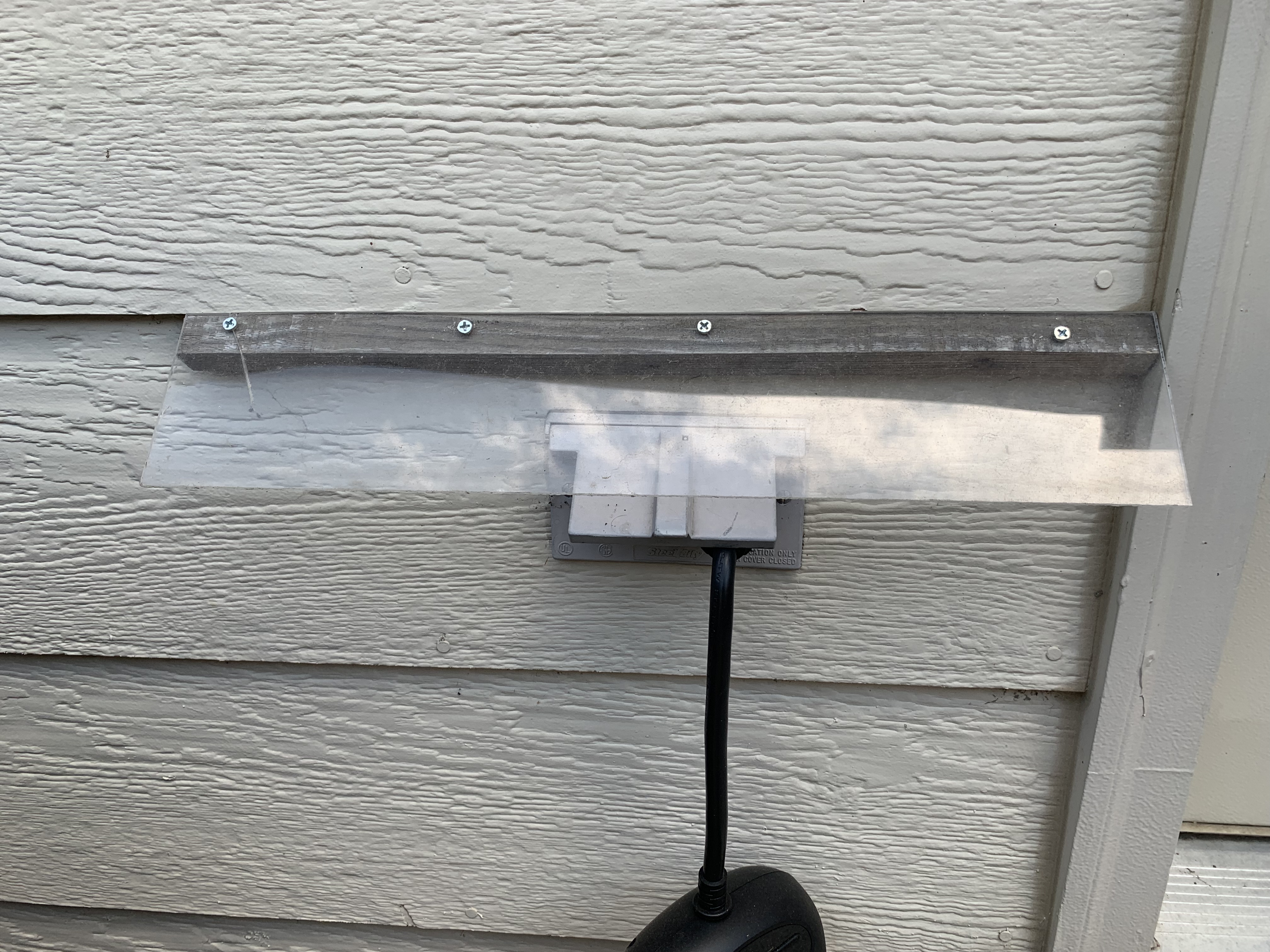
While it works for just the outlet, the current cover falls a bit short of covering the new smart plugs.
So to fully define the project. I want a device that will direct precipitation away from the house and outlets while providing a lit view of the outlets. This system should be self-powered (I'd rather not lose an outlet to powering this) and illuminate the outlets only when necessary. This breaks this project into two smaller projects; an electronic setup that will work well for most solar-powered lighting projects and the enclosure for such. I'll use an Arduino Pro Mini and the Sunny Buddy as well as a mini photocell and 3.5W solar panel for the electronics, but there are many ways that you can configure this project.
3D Printing
Ah, our old friend the 3D printer will come in handy here. The design is fairly simple, we want a roof-like structure to go over the outlet that will direct water away from the side of the house and the outlet. It'll need somewhere to store the MPPT Tracker for the Solar Panel and the Pro Mini controlling the LEDs and reading the ambient light sensor. The "roof" will have a way of keeping the solar panel securely in place. Finally, holes on the underside to mount the LEDs and a hole on the side for the photocell to properly detect the ambient light. This is definitely a structure that can be done with the laser cutter, but I feel this 3D printed part will make for a cleaner solution. I'll provide this direction for the structure, but stop short of providing the files for you. The big reason is I want to utilize the screw holes that are already in my siding, so not only does it not look right, but it probably won't work for your own application. If you really want the file, send me a private message.
The final design looks like this:
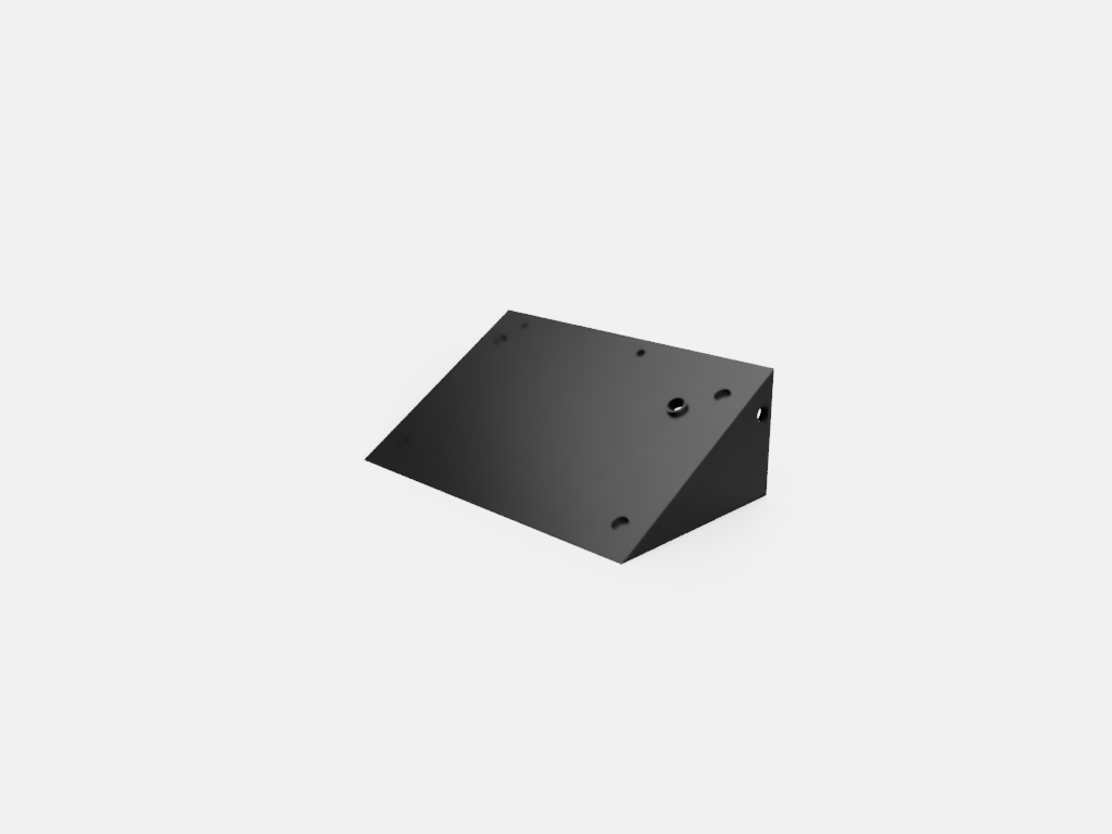
There's 1 hole on the "roof" part which is a port for the solar panel's cable.
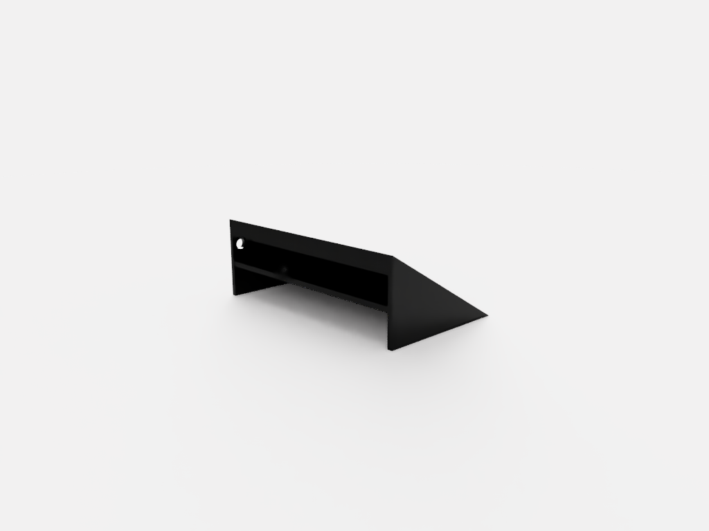
The shelf inside the structure will hold all the electronics with the exception of the solar panel.
It should keep everything dry and happy while providing a clean mounting point for the solar panel. Again, I'm not happy about the mounting points of the structure, but I'd be less happy with more holes in the siding on my house.
Electronics
The electronics are fairly simple; A Pro Mini, Sunny Buddy, 3.5W Solar Panel, Mini Photocell, 3 Super Bright White LEDs (5mm), and 3.3V Lipo Battery. In addition, you'll want wires and connectors for hooking everything up. You'll notice most of my projects use connectors and more temporary wiring solutions. When you have a clean enclosure for a project, you can sacrifice some of the cleanliness of the wiring in the interest of making parts more reusable/swappable. Finally, don't be lazy like me, use current limiting resistors on your LEDs to keep them happy and healthy. Also, a 4.7kΩ Resistor is needed for the voltage divider circuit for the photocell.
The LEDs will each be hooked up to their own digital pins on the Arduino (though you could do one I/O pin, this offers a bit more configurability). The Mini Photocell connects to one of the analog pins. But before that happens, I need to figure out some base readings for the light in the area this will be in. Using the hookup guide for the Mini Photocell I'm able to get proper readings for the day, shade, dusk, and night. I really only want an on/off configuration, but with each LED having their own pin, the potential for different lighting for different situations (if you use PWM pins, you can add dimming to the configurability). With the readings I want for day/night, I can set the threshold for our if-then statement in our code below:
//Illuminated Outdoor Outlet Cover. Most of this code was derived from         Hookup Guides on SparkFun.com for the various parts used.

const float VCC = 3.22; //Measured Voltage of Pro Mini Pin.
const float rVal = 4650; //Measured Resistance of 4.7 Ohm resistor.

const float DARK_THRESHOLD = 10000.0; //Threshold for light and dark, the one from the hookup guide for the Photocell works well.

void setup() {
  // Set pins to control 3 White LEDS individually (set both power and             ground pins as an output):
  pinMode(2, OUTPUT);
  pinMode(3, OUTPUT);
  pinMode(4, OUTPUT);
  pinMode(5, OUTPUT);
  pinMode(6, OUTPUT);
  pinMode(7, OUTPUT);

  //Set the Pin Connected to the Photocell Voltage Divider output as an          input.
  pinMode(A0, INPUT);
 }

 void loop() {

  digitalWrite(3, LOW);
  digitalWrite(5, LOW);
  digitalWrite(7, LOW);

  //Read Photocell and Calculate

  int sensorVal = analogRead(A0); //Get the sensor reading.
  if (sensorVal > 0) {
    float photoV = sensorVal * VCC / 1023.0;
    float photoR = rVal * (VCC / photoV - 1.0); // Calculate the resistance at current reading.

    if (photoR >= DARK_THRESHOLD) {
      digitalWrite(2, HIGH);
      digitalWrite(4, HIGH);
      digitalWrite(6, HIGH);
    }
    else
      digitalWrite(2, LOW);
      digitalWrite(4, LOW);
      digitalWrite(6, LOW);
  } //If the resistance is above the threshold turn on the LEDs
  delay(60000); //Check reading every 60 seconds.
 }
Now the Photocell gets hooked up to the Pro Mini. The 4.7kΩ Resistor mentioned above gets hooked to the ground wiring as shown in the Hookup Guide here.
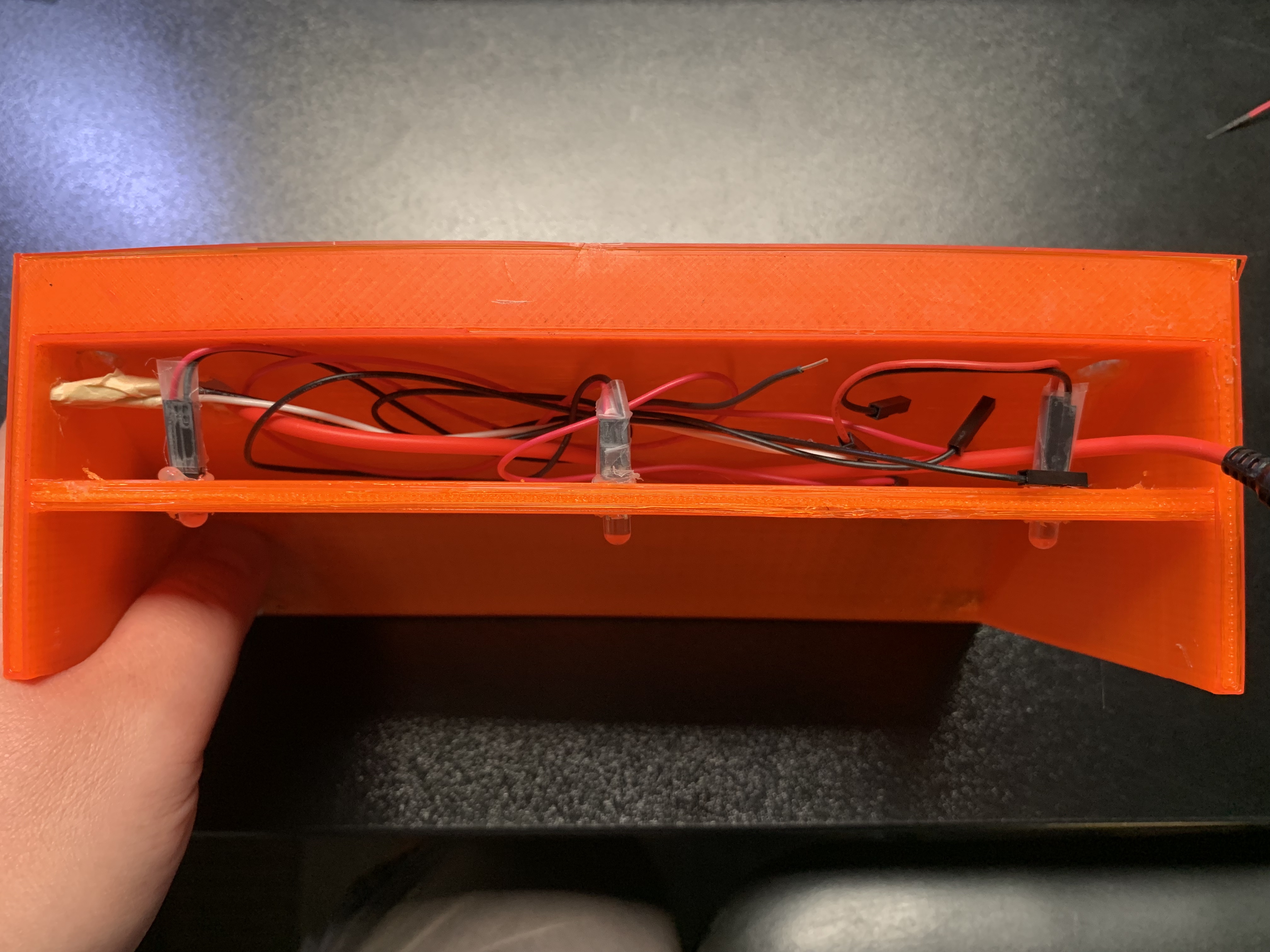
As you can see, it's a tight fit in there, but everything fits fine (just not the most visually appealing
Once the code is loaded and ready to go on the Pro Mini and the Photocell and LEDs are hooked up, we can turn our attention to the Sunny Buddy. For this use, it's very plug and play. Before plugging things in, it's important to set the input current limit. Our Sunny Buddy Hookup Guide has a good section on how to do it and why. Once that's complete setup consists of plugging in the solar panel and powering the Pro Mini through the "Load" pins. For what I'm looking for out of the project, it is complete at this point. However, there's much more that can be done with a setup like this.
The Real World Test
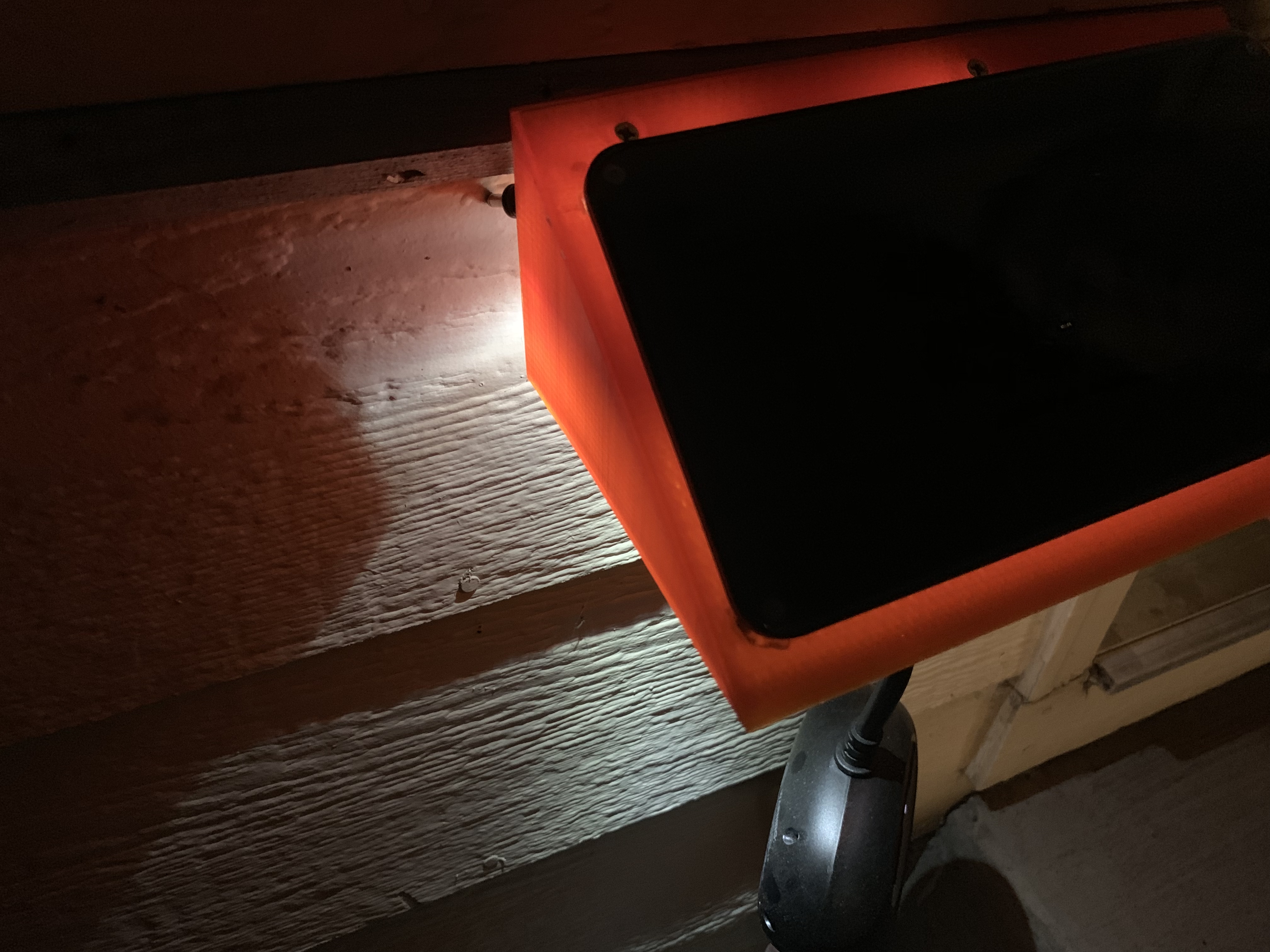
I should mention the filament color is because someone forgot to order more Chroma Strand Black ABS for the department (it was me, I forgot to order more).
Of course, I always think everything is going to be a breeze and go perfectly, so I never leave room for error. If it isn't clear yet, this is a section on my mistakes (lessons to take into account for you the reader). The finished product looks great. Well, 2/3rds of the finished product looks great. I had some issued with some warping on the print which is easily fixable, but I didn't have the time to do so. I'll update photos later with the final print. I also broke one of the crucial rules of electronics projects; test before you glue. For this reason, only 2/3rds of the LEDs function correctly. But to refer back to my choice to use connectors rather than soldering wires, this will prove to be a small issue in the long run.
In something I refuse to take the blame for, I was unable to actually mount the structure as well. What I thought was the screws holding the current precipitation blocker in place (see the first photo) only holds the acrylic to the woodblock underneath. There are two screws on the underside of the wood that holds it to the side of the house. This will take a bit of redesign in the CAD program, but again is not the end of the world. Still, the lesson here is make sure you fully understand how you're mounting a part you're designing before doing so.
Beyond that, everything else functions as expected. I will be adding weatherstripping to the side of the structure that touches the siding.
Interested in learning more about LEDs?
See our LED page for everything you need to know to start using these components in your project.


OFF TOPIC (sort of): I had to laugh at this: I was in. Costco this afternoon, and saw great big Costco-sized boxes of Lego blocks, and noticed that the "Age Range" said "4-99". Hmm...
I saw those too... it had a bazillion pieces (aka ~5000). I really wanted to call and ask how 99 is the limit... why not just throw out the ∞?
Great project! Thanks for posting!
One thought on a way to improve it, without adding any hardware, is to count the number of "minutes" that the photocell indicates "full daylight", so that you have an idea of how much charge the battery has gotten. Then decrement the count when the LEDs are on, and if it gets below a certain value, decrease the brightness of the LEDs (and the frequency of decrementing the count). This could be used to help assure that the light is available, even after a run of cloudy days.
Great project!
In our jurisdiction, outside electric outlets require an "In-Use" cover. It is designed to allow for cables to be plugged in and provide weather protection. At Home Depot, search "Red Dot In use heavy duty outlet cover". The covers even provide a padlock tab. Your plug cannot be disconnected by soemone else.
It fastens on to an existing electric box and includes gaskets and a hinged cover. Available with clear or opaque cover.
1-Gang Universal In-Use Weatherproof Cover, Vertical/Horizontal Extra-Duty Cover, From the Home Depot Canada site Model # CKPM-W-CN Store SKU # 1000856799
Something like this would provide a weather resistant space and security for a device.
Yea, those are a great option too! Just saw an opportunity for a project.