Enginursday: Ten Years of Testbeds
We collected over two hundred retired testbeds and turned them into art! Join us as we highlight this project and tell some of the stories behind these dusty old circuit boards.

Since SparkFun's humble beginnings, testbeds have been a vital part of our production. In the wake of innovation, many of them get retired. Every couple years, the quality control team looks through all of the testbeds down in production. During these audits, they usually find 50 or so that need to be retired.
I was always sad to see them get pulled from the shelves in production because there is usually a lot of blood, sweat and tears that go into each of these designs. I myself played a large part in a lot of their development, so I started collected them throughout the years. A lot of them were disassembled, and their parts were re-purposed in other designs, but I also kept some of the more unique ones in a box. I knew I'd put them on display someday, but I wasn't quite sure how. About a year ago, I got motivated and set them all out on my table:
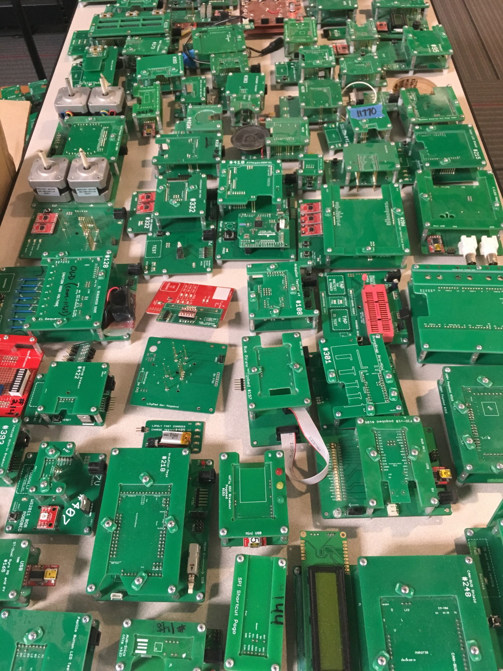
"Wow. That's a lot of testbeds."
The Plan: Mount them to clear acrylic!
After spending some time organizing them on a big table, it became quite clear that they needed to be mounted to some acrylic with sweet laser etching and light up with hundreds of addressable LEDs. Let the scope creep begin!
The first challenging part was to build the files necessary to laser cut all of the mounting holes. A co-worker chatted with me about the project, and he had the most ingenious idea as to how to create the mounting hole files: use an old-fashioned copy machine!
"Don't mind me. Nothing to see here."
We got a few strange looks as co-workers walked by, but managed to make some great image files that came out looking like this:
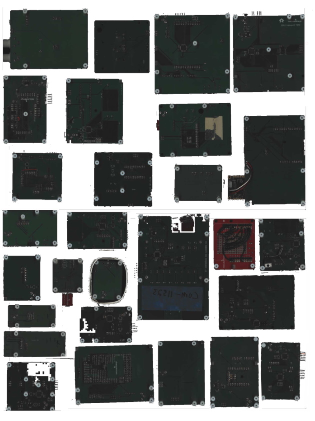
Photocopy machine image for Panel 0.
This dramatically sped up the design process. There was no measuring or spacing required. We simply placed the beds on top of the copy machine with the desired spacing, and hit print to PDF! Then we could simply import these files into Paint.net and place drill hits as needed. Wahoo!

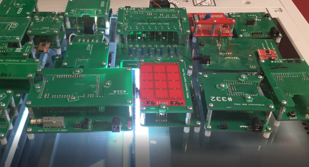
The first four panels with all the testbeds mounted. The process is working!
The Frame
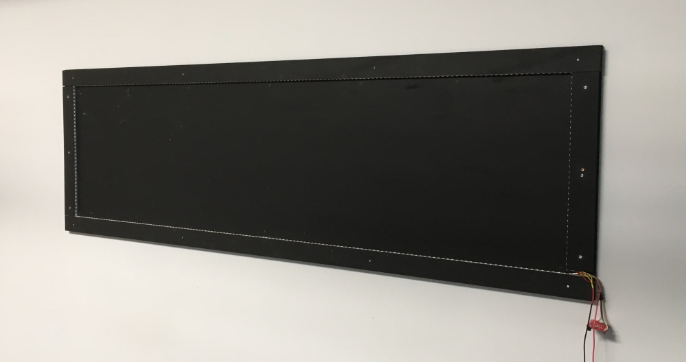
The custom, 30"x96" frame mounted.
The frame was built with three layers of wood. The backing was a solid piece of 3/4-inch plywood. Then we built an "inner" frame.
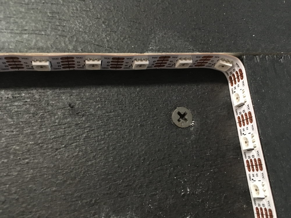
Close up of a corner. We got really lucky with the "bend points" on the LED strips.
This provided a nice, right-angled surface for the LEDs to stick to, and when we positioned the inner frame pieces, we were able to ensure that the LEDs were very tight up against the edge of each acrylic panel.
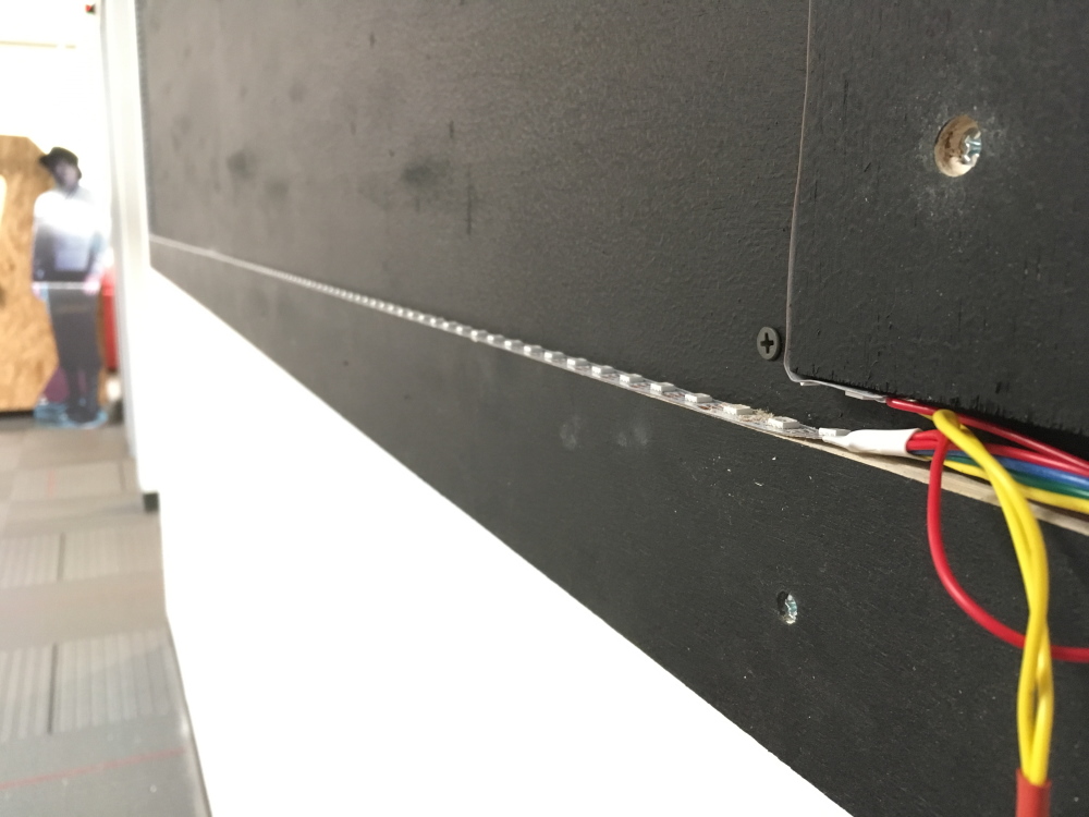
Escape channel for wiring.
On the bottom right corner, we cut the inner frame slightly short to allow for the power and control lines to escape.
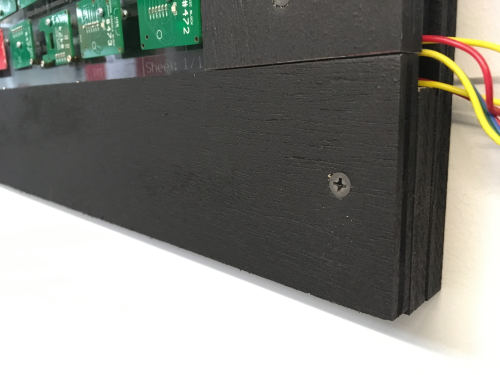
Close up of the frame top layer.
The final layer is also made of 3/4-inch plywood blanks, and it was cut so that it would hang over the LEDs about 1/4-inch. This simply covers up the LEDs a bit and adds a nice finished look to the piece.
The Acrylic Etching
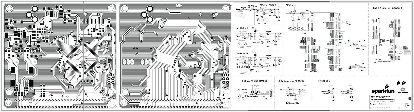
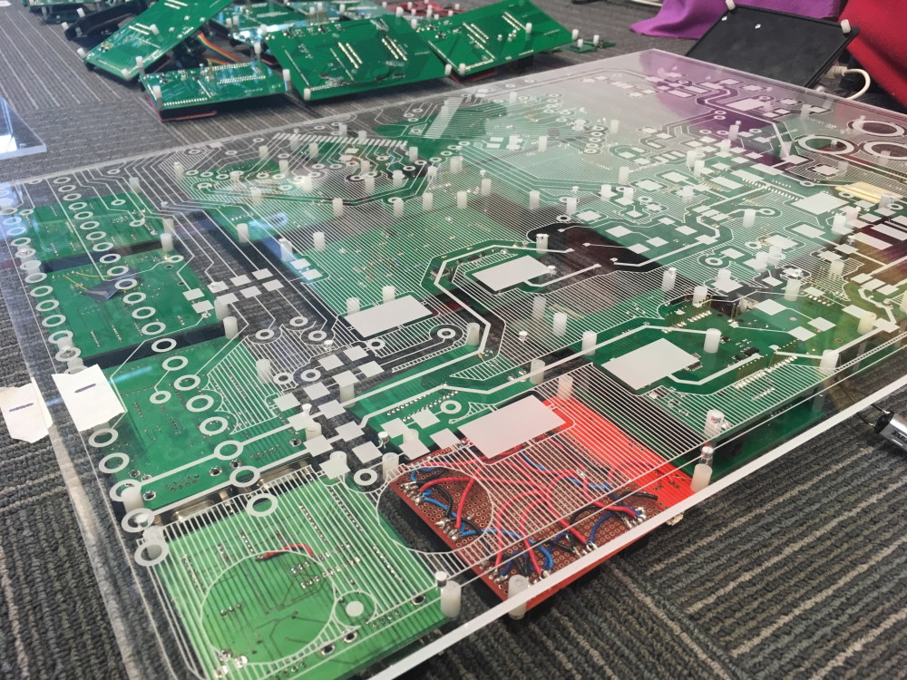
The large image etched behind all of the testbeds.
The design that is etched into the panels is actually the Flying Jalapeno Testbed brain. The left section is the top copper, the middle section is the bottom copper, and the far right is the schematic. We actually just printed to PDF straight from Eagle, then imported to Illustrator and did a little stretching to fit. We really loved how the ground pours came out as lines - unintentional, but nonetheless it looks awesome with the side-lit LEDs!
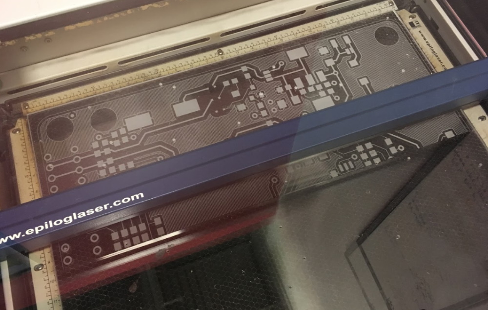
Our laser printer mid-print. Starting to look awesome!!
Each panel took over an hour to etch. We had five panels, so it took some time, but it was worth the wait! We had never done an Illustrator file with "panels," but it was actually quite easy to deal with and we used the "range" option to print each panel individually.
Here's the first panel etched with the testbeds staged for mounting.
It was so exciting to see it come together! Next up, we needed to mount all of the testbed. Even with just two screws per unit, it was quite a long time to get them all back on there!
The Lighting
To light up the acrylic, we mounted about six meters of our RGB LED strips of addressable APA102s. We needed 5.8 meters to make it all the way around the panels, so we combined a 5m strip and a 1m strip. They are pretty easy to solder together. Tip: cut the additional strip in the middle of the pads, but cut the preceding strip so that the entire pad is remaining. This way, when you overlap them before soldering, you have plenty of metal to get the solder to flow between sections.
In total, it was 498 LEDs. Running at 5V, we only saw our bench-top power supply showing up to 2.5A. We don't intend to ever turn on all LEDs at full brightness, so we opted for a small-ish power supply: the Mean Well LED Switching Power Supply - 5VDC, 5A, capable of providing 5 Amps of current at 5V, which should be plenty for our needs.
If you are interested in seeing some of the code that is currently controlling the LEDs, you can see it at the project GitHub repo here.
Testbed Bravo Charlie Echo Foxtrot

Close up shot of some of the earliest testbeds.
When I first started at SparkFun in 2007 as an assembly tech, most of the testing equipment was in a pile (including the testbed on the left: Testbed Bravo). If you needed to test something you just built (by hand), then you searched the shop for the testbed you needed, searched through a folder on the production computer (not backed up), and eventually found a paragraph of text that was the test procedure. If you couldn't find the testbed, you had to bug an engineer to help you get another setup going.
This was also in the days before using pogopins, so most of the connections made to a product during testing were made by holding a row of headers on the product onto a row of male headers on the breadboard. If you held it with just the right pressure, for just the right time, then you might get 50 percent of your boards to pass!
Most of the testing equipment was created by the engineer on the design, and it usually consisted of a breadboard setup and was only intended for testing the prototype. We didn't have time to design a better piece of hardware - we only had time to get the next little widget out. Eventually, the engineers helped design "testbed Alpha," which was a design intended to test many different products. Then came Bravo, then Charlie, all the way up to Foxtrot. Never made it to Golf!
These testbeds can be found on the bottom left of the installation. As you move right, you will see newer and newer designs.
The Edison Panel
An entire panel was dedicated to just the Edison testbeds.
The SparkFun Edison blocks were an ecosystem that supported the now retired Intel Edison. These testbeds required a large collaboration between the engineers and the quality control testbed design team. We worked together to keep the designs somewhat consistent. We even created custom Eagle parts for the "sub-board connectors."
The real challenge with this product (and testbed design) was the fine-pitched connector. We knew it was going to be difficult to get great yields in production, so we wanted to design testbeds that actually tested 100 percent of the pins for cold joints and jumpers. This requires some neat tricks with a technique we coined "saddle stitch" net testing. It was a slightly odd way to connect all of the unused pins so that you could quickly test for cold joints and jumpers.

Schematic screenshot of the "saddle stitch" testing method.
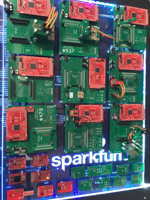
ProtoSnap

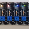
The ProtoSnap Pro Mini testbed
The ProtoSnap product line was not only an interesting product to develop, but it also required some creative solutions in production testing. The version shown above uses a technique to hold the board in place called "nubbins." You simply place the board down, and then turn the nubbins to lock it down. This worked okay, but it eventually needed to have something more ergonomic, and these testbeds were revised to use another technique called the "waffle top," where a custom layer on a hinge would come down to hold the board in place on top of the pogo pins. Along with its testbed, this product has also been retired, but it's fun to see the known-good board is still attached to this testbed, and to think how the ProtoSnap idea has since been incorporated in other products such as the BITalino and gator snaps.
The Penguin
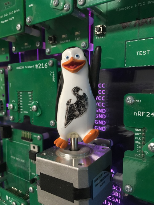
Retired and still smiling.
Ah yes, everyone always asks about the penguin. This little testbed was for the Easy Driver, a stepper motor driver. The tech would simply place the product down on the testbed, and it would cause the motor driver to move back and forth. Why not attach a little model penguin to the motor? It sure was a crowd pleaser!
Closing Thoughts
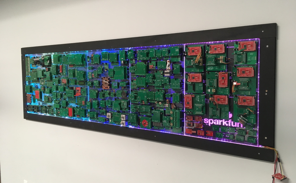
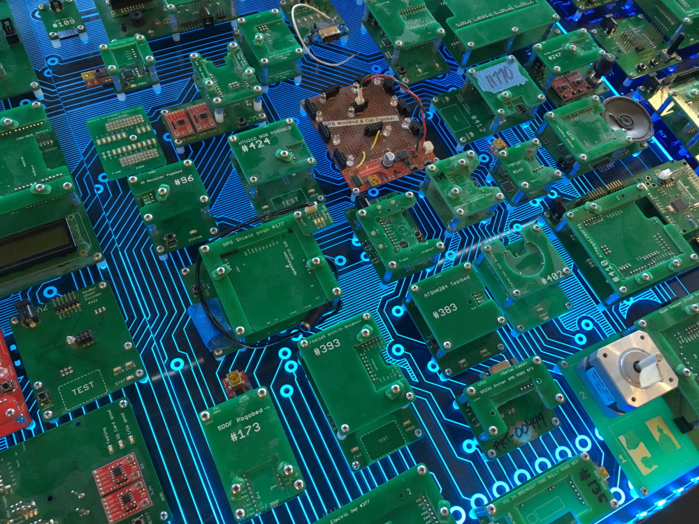
It's up and running!
Overall, we are really pleased with how this turned out. It is mounted on a wall near our big open space where we have our weekly, company-wide meetings, and our engineering group design reviews. It is nice to know that it will get a lot of day-to-day traffic and hopefully remind people of our accomplishments, inspire greatness and just generally brighten up their day.
So often, we launch a product and then we jump on the next project and don't spend much time thinking about the accomplishment. It's important to take a moment once in a while and reflect back.
We're also excited to see if anyone wants to help write some code for new modes on this thing. A few people around here have shown interest, and so we intend to build this out to have at least a few more modes. If you have any interest, or simply want to see what some of your blinky APA102 code looks like on this installation, please comment below or hit us up on GitHub. We'd be happy to try it out!
Hope you can stop on by for a tour some Friday and see it in person!
Resources
Products used:
- RGB LED strips of addressable APA102s
- RedBoard Turbo
- Mean Well LED Switching Power Supply - 5VDC, 5A
GitHub links:
If you are interested in testbed design and general quality control topics, then you might like to read some of our past blog posts on the subject matter. Check them out here:
- Sneaky Footprints (2008)
- PogoBeds: SparkFun Production and Testing (2009)
- Ganged Programming with AVR ISP MKIIs (2011)
- Constant Innovation in Quality Control (2013)
- Enginursday: A new and improved IOIO-OTG! (2016)
- Raspberry Pi Stand-Alone Programmer (2018)
- Enginursday: Innovative Testbed Design Part 1 (2018)
- Enginursday: Innovative Testbed Design Part 2 (2018)


Great project, Pete! I hope that sometime I'll get to take the Sparkfun tour again and see it in person! (Unfortunately, due to "family" health issues, that's not likely in the near future.)
And, you gave me an opening to mention something else that IMHO would look great with some programmable LEDs inside the "empty box": Costco is, again this year, having a sale on "crystal" boxes containing 48 Ferroro Rocher candies for under $10 (at least here in the Phoenix area). Fantastic price on the candies, AND you get a faceted plastic box just begging for an LED project to be put into it!
Thanks #773! We hope to see ya on a future tour - whenever that may be.
This was my first time using addressable LEDs in a project, and it was great fun. Now I'm looking at everything and thinking, "dang, that would be cool to line with LEDs". Let us know when you finish your chocolates and make your next blinky project :)