Enginursday: How to Build a Levitating Light
Check out our latest tutorial on levitating magnets and creating a wireless light!

A couple years ago, I showed off a project where I made a levitating light.The post had some traction initially, and slowly fell back into the shadows of the internet...or so I thought. Recently, there's been an increase in the comments from customers that were trying to build one themselves but having some difficulty getting it working. If you didn't see it, below is the original video I filmed for the post.
Because of the renewed interest, and the complexity of the build, a short video doesn't go into enough detail. So I wanted to revisit the project and make a tutorial that walks through the more intricate details involved. If you were someone that saw the post and wanted to make it but needed more information, or if this is your first time hearing about it and you would like to build one, check out our new tutorial!
Magnetic Levitation
November 20, 2019
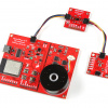
This tutorial will show you how to build a magnetic levitation circuit using common parts.
Interested in learning more about LEDs?
See our LED page for everything you need to know to start using these components in your project.


Amazing. As you have provided a tutorial too. Now people would take more interest in this and maybe they try to build it. Keep sharing such type of articles of innovations.
Yaaaaes. I saw this project a while back. It's so cool. Magic. =)
i already checked out the blog, but i got some question to discuss here. are the levitation circuit and the wireless power transfer different circuit? so do we need 2 mosfet for all circuit? or can we combine them into a circuit which only needs a mosfet? thank you
Yes, the mosfets do need to be different. The reason is with the levitation circuit, you only want to energize the inductor when the magnet is too far away from the hall effect sensor. With the wireless power circuit, you want to be constantly switching current to induce a current on the receiving coil.
okay alex, i already got one more mosfet. but there's a trouble. i already followed your tutorial, it works until "the comparator circuit". but "levitating the magnet" doesnt work. i got another model of inductor, but it has the same specs, 1mH. here are the symptoms: i can feel some vibration coming out from the inductor, and the inductor is really hot, more than the mosfet. is it normal?
What kind of magnet are you using and what size is it? The inductor will get warm/hot when a lot of current is running through it. The only time I noticed my inductor getting pretty warm was when I was levitating something with a bit of mass on it, like the LED and receiving coil.
I would suggest double checking the wiring on the comparator circuit, or even just try swapping the connections to the inputs. If the hall effect sensor output and the trim pot are wired backwards, the comparator might be sending current opposite of what you want.
It's also possible that the inductor is wired backwards and repelling instead of attracting the magnet. The last thing I would suggest trying is I noticed that with some of my stronger magnets, the magnetic field might be too strong. You could also try replacing the SS494 (+/- 42mT) with the SS496 (+/- 84mT)
i use a tiny neodymium magnet, 3x12mm. the inductor is really hot, but the magnetic field is really weak. i only feel a vibration coming out from the inductor. the inductor is really hot even though b
Do you have a link to the inductor you're using?
https://images.app.goo.gl/1eWBwa143gdrzjnFA inductor is like that
Ah ok, the inductor is the issue. When you pass current through a wire, it generates a magnetic field, the more current you can pass through the wire, the stronger the magnetic field will be. That inductor you linked has a current rating of 0.3A, and the inductor I linked has a continuous current rating of 3.6A. Here's a link to the inductor I used
since it's hard to find the exact specs of inductor here, can i use a toroid inductor? https://www.bukalapak.com/p/elektronik/komponen-elektronik/84bjmh-jual-induktor-ring-coil-470-uh-3a
I think what you would want would be closer to this
Nice blog! How much resistance do I need for an LED? and one more thing can you give me the Tips to reduce the electricity bills.
The LED is rated at 3W and the received power is about 136mW, so there's no need for a current limiting resistor. Best tip to reduce electricity bills I have is to use less electricity, and thus your bill will be lower :P
Could these be made larger? Say, outdoor porch light size?
I don't see why not, but from a practical side, if the light falls it's probably going to break the LED. The levitation driver could be modified to cut the current of the inductor until the magnets are in range again, but currently if the magnets fall, the current stays on to the inductor to try and pull the magnets up which draws a bunch of power and even with the small-ish inductor, it gets pretty hot with full current.