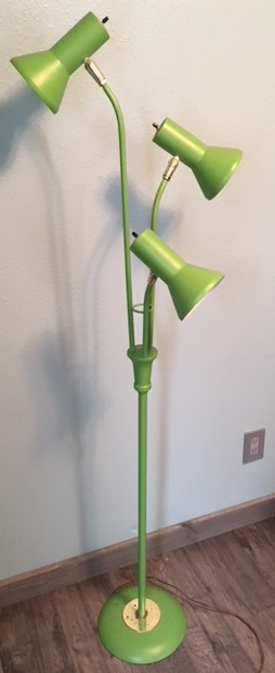
In the spirit of the three R's, I decided to update an old, broken incandescent lamp with some addressable LEDs and trimpots.
The poor old lamp was on a steady decline, and after the second of the three lamp heads failed to power its bulb, it was clear that the old fixture was on its way to becoming fully dysfunctional. Needing to fix the old lamp presented the opportunity to upgrade its old, power-hungry internals with some more efficient and functionally-rich replacements. I began disassembly to see what we were working with.
Disassembly
The lamp itself is nothing unique; it has a metal body that can be pretty easily separated into two main parts: the stand and post, and what I'm calling a "collector," with the three necks and lamp head on each. The two can be separated by unscrewing the post from the collector and cutting all cables connecting the two parts. The plan was to gut all of the original circuitry, so it was easiest just to cut any cables that got in the way. Once separated, the cables could be pulled free from the stand.
Each lamp head is connected to its respective neck by a pass-through fixture that acts as a swivel, allowing the cables from the collector/neck to pass through to the head of the lamp. These were easily removed by unscrewing two screws - one acts to clamp the two halves of the swivel to the neck, and the other retains an elbow that carries the lamp head. The same process was followed to separate the two other heads from the necks, allowing the remaining wires to be pulled from the collector and necks.
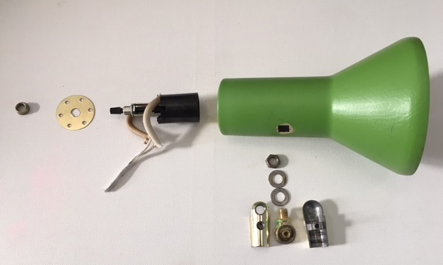
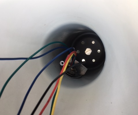
The lamp heads proved the most bothersome to disassemble. Within each lamp was the switch and bulb assembly, which was fixed to the elbow portion of the swivel by two washers and a retaining nut. Because of clearance issues, it was more or less impossible to fit a standard-width wrench onto the retaining nut. Luckily I had some skinny wrenches that would work, but it was still a big pain only being able to turn the nut about 40 degrees before having to reset the wrench.
Once this nut was removed, the elbow portion of the swivel could be removed from the lamp head, leaving the switch knob nut at the back of the lamp head as the last piece of hardware. Removing the switch nut allowed the switch and bulb assembly to be pulled from the lamp head, leaving it empty.
Finding some new parts
In an effort to increase efficiency and functionality over the old incandescent setup, I opted to replace the light-emitting components with addressable CRGB LEDs. With many options out there, I set out around the office to see what some of the more experienced addressable LED users would recommend for the application.
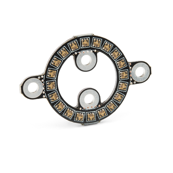
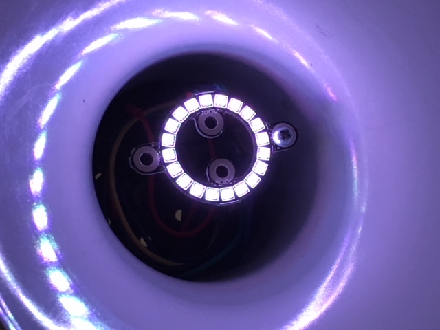
I decided to use one of our LuMini LED Rings for each of the lamp heads. The LuMini rings seemed a good fit - the shape of the ring coincides with the shape of the lamp heads, and they have handy mounting points I could use. These LED rings are available in three sizes, with LED count increasing respectively. I opted to use the SparkFun LuMini LED Ring - 1 Inch, which employs 20 APA102 addressable LEDs.
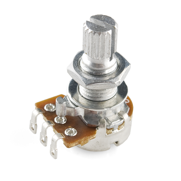
I set two initial goals for this project: the first was to be able to adjust the brightness of each lamp individually, and the second was to be able to change the color the lamps emit. I decided to add a trimpot to each lamp head that would take the place of the old rotary switch, as well as add one trimpot to the stand of the lamp. The trimpot on each of the heads would adjust the brightness of the corresponding LEDs of that lamp head, and the trimpot in the stand would control the color of all the LEDS. For this job I chose to use four 10K Ohm linear rotary potentiometers. Coinsidently, these trimpots mimic the look and size of the old rotary switches, which proved very handy for installation.
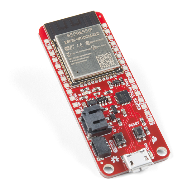
It was finally time to choose a microcontroller that would both suit the immediate application and not limit the future addition of features. I decided on the SparkFun Thing Plus - ESP32 WROOM as the brain of the lamp, because of its wireless capabilities and the functionality that accompanies them.
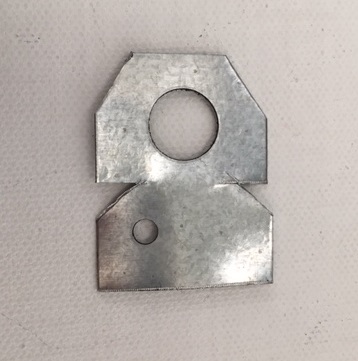
The last item to flush out before assembly was the method for mounting the LED rings to the lamp heads. The previous switch and bulb assembly had a bracket integrated into the assembly, so I needed something similar in width that I could shape to fit the application. After looking around the hardware store, I settled on using some stainless steel lumber framing brackets.
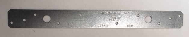
What’s nice about these brackets is that they were pre-drilled with apertures that would suit the application: a large hole that would fit over the threads of the hinge, and a smaller hole that could be used to attach 4-40 standoffs to mount the LED ring. The stainless brackets are also thin enough to easily cut with tin snips and bend with pliers. At this point it was time to begin assembly.
Assembly
I started by measuring and cutting all the lengths of wire I would need, and sorting them based on what the wires would connect to. The schematic is below.
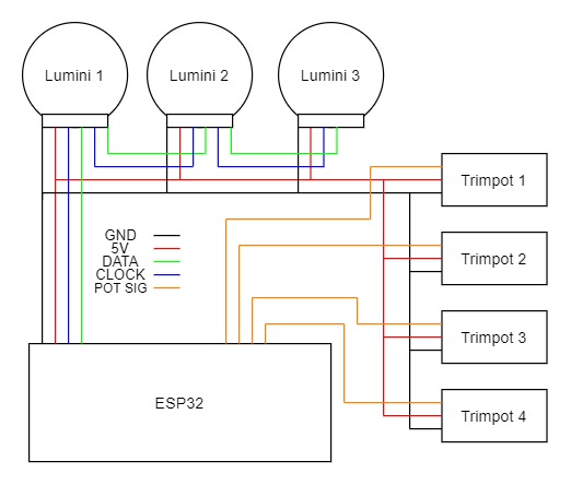
Anyone who has pulled cable/wires knows how big of a pain this can be, and this situation was no different. Taping the wires to a straightened coat-hanger or a string proved to be the easiest method of getting the wires through the various sections of the lamp. Because the APA102 LEDs require that they be daisy-chained to function on the same bus, an extra set of data and clock wires for the outgoing signals from the first and second ring were needed - this increases the wire count for those two lamp heads by two.
There were some sharp edges of metal on the inside of the collector where each of the neck pipes joined. These edges could easily strip the sheathing from a wire or even cut the wire completely - I taped the edges I could reach.
Once all of the wires were pulled through the necks and the collector, I taped all the wire ends to the nearest surface to prevent the wires from being pulled out accidentally when pulling the other ends.
Next I cut and bent the brackets. I worked around the pre-drilled holes needed and cut just that portion from the rest of the bracket. Because the lamp head is round, and the bracket would need to sit more or less flush against the inner wall, I cut some wedges out of the sides of the bracket and bent the piece into a 90-degree “V” shape. After a couple tweaks and bends, the bracket seemed to fit well enough.
It was now time to assemble each of the lamp heads. The wires had to be pulled through the mounting hole of the lamp head and all of the other retaining parts before I could begin soldering the components to the ends. I found laying the parts out in the order that the wire had to pass through them to be helpful. In this case, the wire bunch had to pass through each part in this order: swivel (one half), swivel-elbow, lamp head, bracket, washer, lock washer, retaining nut.
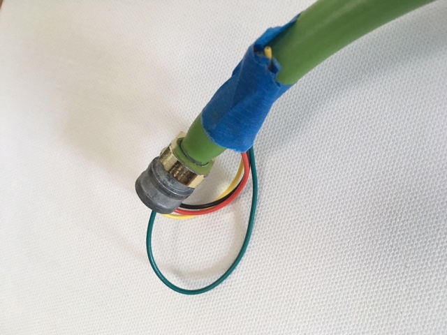
Before I secured the bracket down with the retaining nut, I connected a couple 3/8-inch aluminum standoffs together and fixed them to the bracket, because I wasn't going to have room to secure the standoffs to the bracket once the bracket was in place. After the retaining nut was secured to the elbow I began soldering the potentiometer and LED ring to the wires. I chose to solder and install the trimpot first, as this part had to poke out the back of the lamp head, and like the standoffs on the bracket, I wouldn't be able to secure the trimpot in place with the LED ring installed.
The trimpot needs a power signal, a ground signal and an output signal, while the LED ring needs a power signal, a ground signal, a data in, a clock in, a data out (first two rings) and a clock out (first two rings).
I powered the trimpot and LED ring with 5V, which in the end was a mistake. In an effort to pull the least amount of wires through the lamp as possible, each lamp head was fed one 5V source wire and one ground. This meant I had to splice both the 5V and ground from the trimpot and the ring into the main power and ground sources. I chose to do this with some through-hole, 100-mil pitch headers (female and male) and once inserted, the headers were taped together to hold them in place - I figured this would make any disassembly or troubleshooting easier need be.
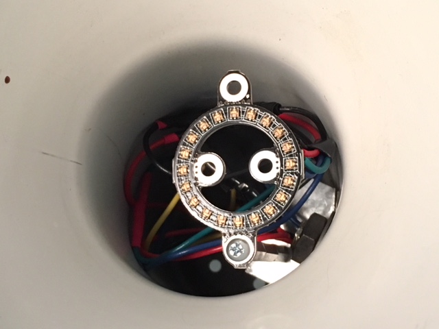
After securing the trimpot to the back of the lamp head, I stripped the ends of the wires going to the LED ring and soldered each to its respective pad. Last, I secured the LuMini ring to the end of the two stacked aluminum standoffs using a 4-40 screw. The same process was followed for the assembly of the other two lamp heads.
To complete the assembly of the collector and head assembly, I pulled the rest of the wires from the collector through the pole and the stand. The pole was threaded into the collector, and to complete the assembly of the lamp, all of the wires were soldered to the ESP32 Thing Plus under the stand.
Coding the ESP
The Arduino sketch below is the current running code on the ESP32:
#include <FastLED.h>

#define NUM_LEDS 60
#define DATA_PIN 18
#define CLOCK_PIN 5
#define short_pot 26
#define med_pot 25
#define long_pot 34
#define base_pot 39
#define short_ring 0
#define med_ring 20
#define long_ring 40

CRGB lamp_leds[NUM_LEDS];

int SHORT_VAL = 0;
int MED_VAL = 0;
int LONG_VAL = 0;
int LAMP_HUE = 0;
int LAMP_SAT = 200;
int PREV_SHORT_VAL = 0;
int PREV_MED_VAL = 0;
int PREV_LONG_VAL = 0;
int PREV_LAMP_HUE = 0;

void setup(){
  pinMode(short_pot,INPUT);
  pinMode(med_pot,INPUT);
  pinMode(long_pot,INPUT);
  pinMode(base_pot,INPUT);

  LEDS.addLeds<APA102, DATA_PIN, CLOCK_PIN, BGR>(lamp_leds, NUM_LEDS);
  LEDS.setBrightness(LAMP_SAT);
  Serial.begin(9600);
  Serial.println("Hello?");
}

void loop(){
  //pull HUE from stand trimpot and pull VALUE from each lamp trimpot
  LAMP_HUE = pot_read(base_pot);
  SHORT_VAL = pot_read(short_pot)-20;
  MED_VAL = pot_read(med_pot)-20;
  LONG_VAL = pot_read(long_pot)-20;
  if(SHORT_VAL < 0) SHORT_VAL = 0;
  if(MED_VAL < 0) MED_VAL = 0;
  if(LONG_VAL < 0) LONG_VAL = 0;

  //debug
  Serial.print("LAMP HUE = ");
  Serial.println(LAMP_HUE);
  Serial.print("SHORT = ");
  Serial.println(SHORT_VAL);
  Serial.print("MED = ");
  Serial.println(MED_VAL);
  Serial.print("LONG = ");
  Serial.println(LONG_VAL);


  //check if current trimpot readings are different than the previous
  if((PREV_SHORT_VAL != SHORT_VAL) ||
     (PREV_MED_VAL != MED_VAL) ||
     (PREV_LONG_VAL != LONG_VAL) ||
     (PREV_LAMP_HUE != LAMP_HUE)){
      if(LAMP_HUE == 0){
        //set ring output to white
        populate_led_settings(short_ring,LAMP_HUE,0,SHORT_VAL);
        populate_led_settings(med_ring,LAMP_HUE,0,MED_VAL);
        populate_led_settings(long_ring,LAMP_HUE,0,LONG_VAL);
      }
      else{
        //set ring output to trimpot ADC value
        populate_led_settings(short_ring,LAMP_HUE,LAMP_SAT,SHORT_VAL);
        populate_led_settings(med_ring,LAMP_HUE,LAMP_SAT,MED_VAL);
        populate_led_settings(long_ring,LAMP_HUE,LAMP_SAT,LONG_VAL);
      }
      //set previous values read
      PREV_SHORT_VAL = SHORT_VAL;
      PREV_MED_VAL = MED_VAL;
      PREV_LONG_VAL = LONG_VAL;
      PREV_LAMP_HUE = LAMP_HUE;
      FastLED.show();
     }
     delay(50);
}

//math on trim signal translating into range of 0-255
int pot_read(int pot){
  long VAL = 0;
  for(int i = 0; i<1000; i++) VAL += analogRead(pot);
  VAL = VAL/1000;
  int CAL_VAL = VAL/16;
  return CAL_VAL;
}
//sets LED settings
void populate_led_settings(int ring_start, int hue,int sat,int val){
  for(int i=ring_start; i<ring_start+20; i++){
    lamp_leds[i] = CHSV(hue, sat, val);
  }
}
I opted to use the FastLED library because of its ease of use, and huge range of LED support and functionality. This was also my first time using the CHSV LED setting structure, which I found to be much more intuitive than the standard RGB structure. The above code functions well enough, but is far from perfect - this could be said for the lamp as a whole.
Using a 5V source for the trimpots was a mistake. First, it's possible to damage the ESP32 by feeding more than VDD+0.3V to any of the GPIO. Second, the ESP32 functions at a 3.3V logic level, which means the chip ends up clipping any trimpot signal voltage that exceeds 3.3V, shortening the usable signal window of the trimpot. If I had fed the trimpot a 3.3V signal I could see greater resolution.
In the meantime, the microcontroller will likely be switched to a ATmega328-based board running at 5V. Some of the math in the lamp sketch will have to be adjusted to account for the difference in ADC bit count, but it's a safe quick fix. Running a 3.3V source through the lamp and returning to the ESP32WROOM is the goal in the end.
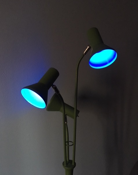
All in all, the project was fun, and it feels good saving an old lamp. Tell us about some of your reused and recycled projects!
Interested in learning more about LEDs?
See our LED page for everything you need to know to start using these components in your project.


This is a nice upgrade project!
Cool hack! But, to be clear, you are NOT powering this from the 120V AC wall socket. Maybe I missed it in your write-up, but you must be using a 5V wall wart or USB power supply or something?
Good point. (*Maybe I interpreted it differently, but I think the author does mention that he is using a 5V power source.)
EROC wrote:
Am I missing something, or why not have the trimpot relative values read directly by the ESP32, then use PWM to adjust the brightness?
It would also eliminate the over-voltage issue mentioned too; the analog read could be done based on 0-VDD instead of 0-5V.
Based on the code and diagram, I believe that is what the author is doing. However, I do agree that if the 3.3V pin were used on the trimpots, instead of 5V, it could possibly solve the over-voltage issue.
First, it's a great project, and also a great way of keeping stuff out of the landfill!
I have a few quick comments: First, running the trimpots off the same conductor as the LEDs means that as the brightness changes there can be a variation in the voltage seen by the pots.
Second, pulling a multiconductor cable can sometimes be enough easier than pulling multiple strands that the extra cost (or hassle) of getting something appropritate might be worth while. (Check hamfests -- you might be able to pick up some "used" cables for not very much money! Even if they have too many conductors, you can consider combining the ones for power and ground, and for this sort of a project, impedance is not much concern.)
Third, with the computer controlling it, it seems to me that it would be fairly easy to do some IoT type things with this, e.g., timers to make it appear that someone is home, or remote controls...