This is part two of a multi-part write up. If you haven’t read part one, check it out before proceeding. Utilmately, the effort is to create a keycode security system for an 80's era car that was not built assembled with one from the factory. The concept is basic – a keypad acts as the HID, and once the correct PIN is entered through the keypad, the microcontroller closes a relay completing the starter solenoid circuit, allowing the operator to start the car in the typical fashion – using a key to rotate the ignition switch thus actuating the starter. Read on for a write up depicting the prototyping phase of the project.
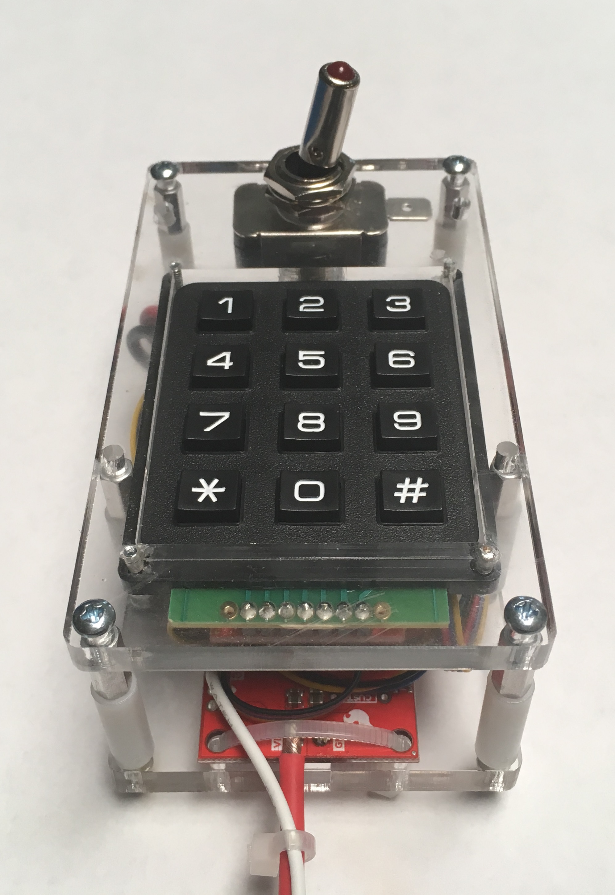
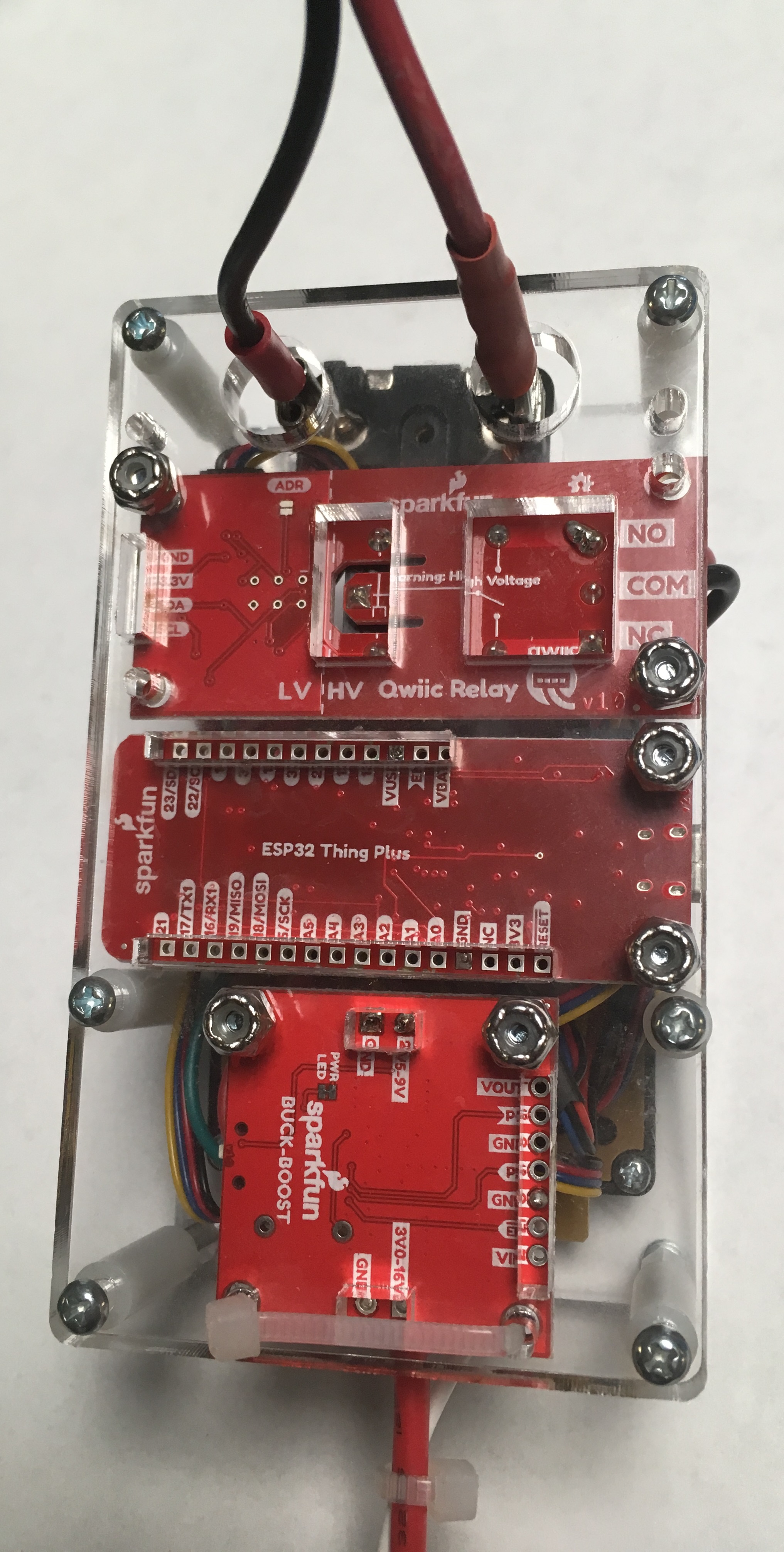
To give myself the opportunity to test the concept and the hardware in the intended operational environment, I created a fixture to house the hardware. There were a few necessary features the fixture needed to have: the components and wires need to be easily inspectable and accessible, and the fixture needs to be small enough to allow me to move it around the vehicle for testing variation. I opted to laser cut two pieces of 1/4” acrylic that I could affix the hardware to. Conveniently, Autodesk's EAGLE PCB layout editor ships with a built-in DXF file generating ULP. The ULP uses the dimension layer to generate the file, so you would just remove all layers except the dimension layer and run the ULP, and you will be treated to a scaled DXF file of your PCB design.
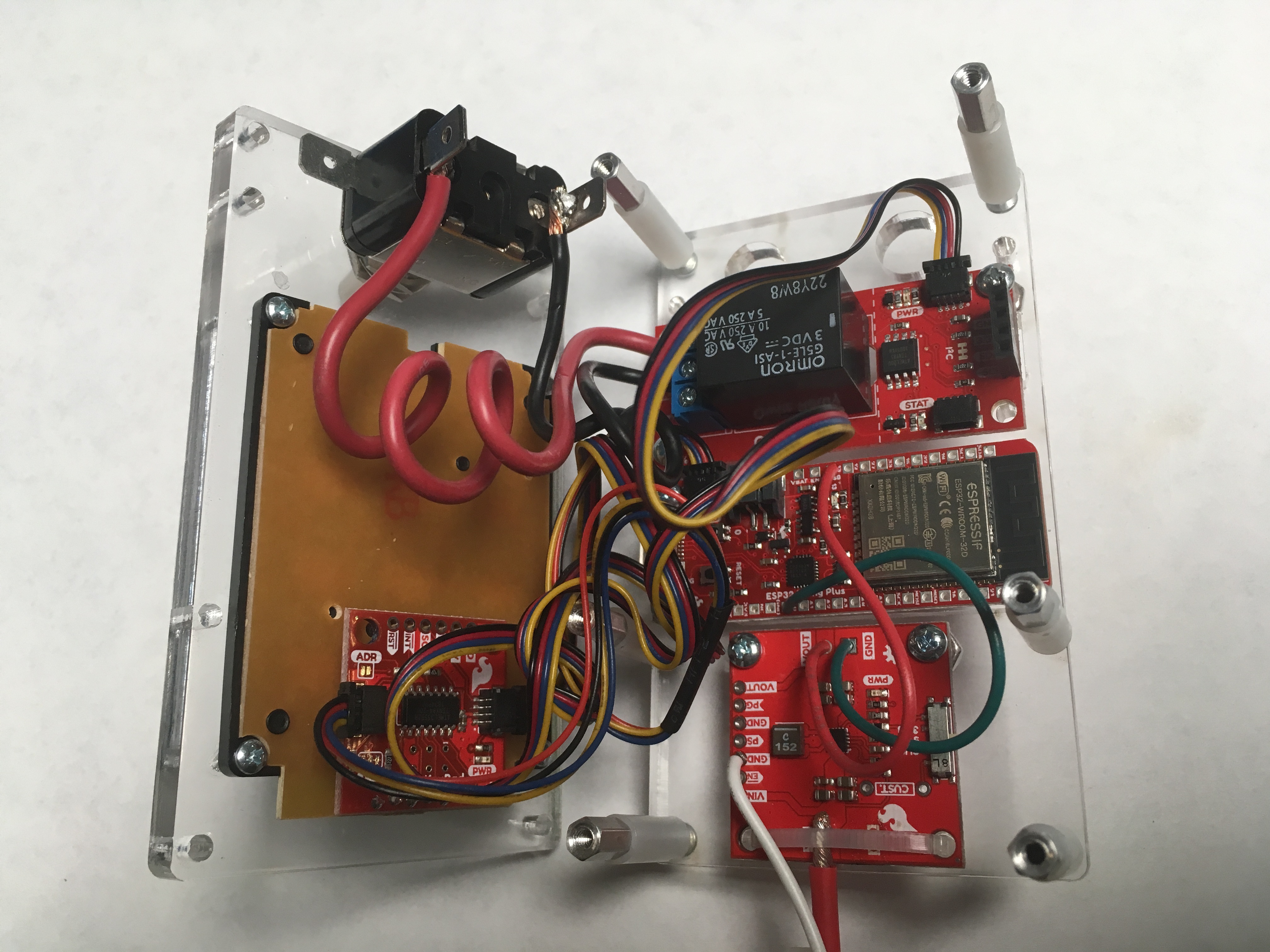
This ULP was the key to producing the acrylic plates (if I didn’t have access to a laser cutter, I would have likely used some thin plywood that I could easily drill and cut apertures into). The acrylic plates sandwich the boards and components, and are held together by a combination of screws and aluminum and plastic standoffs.
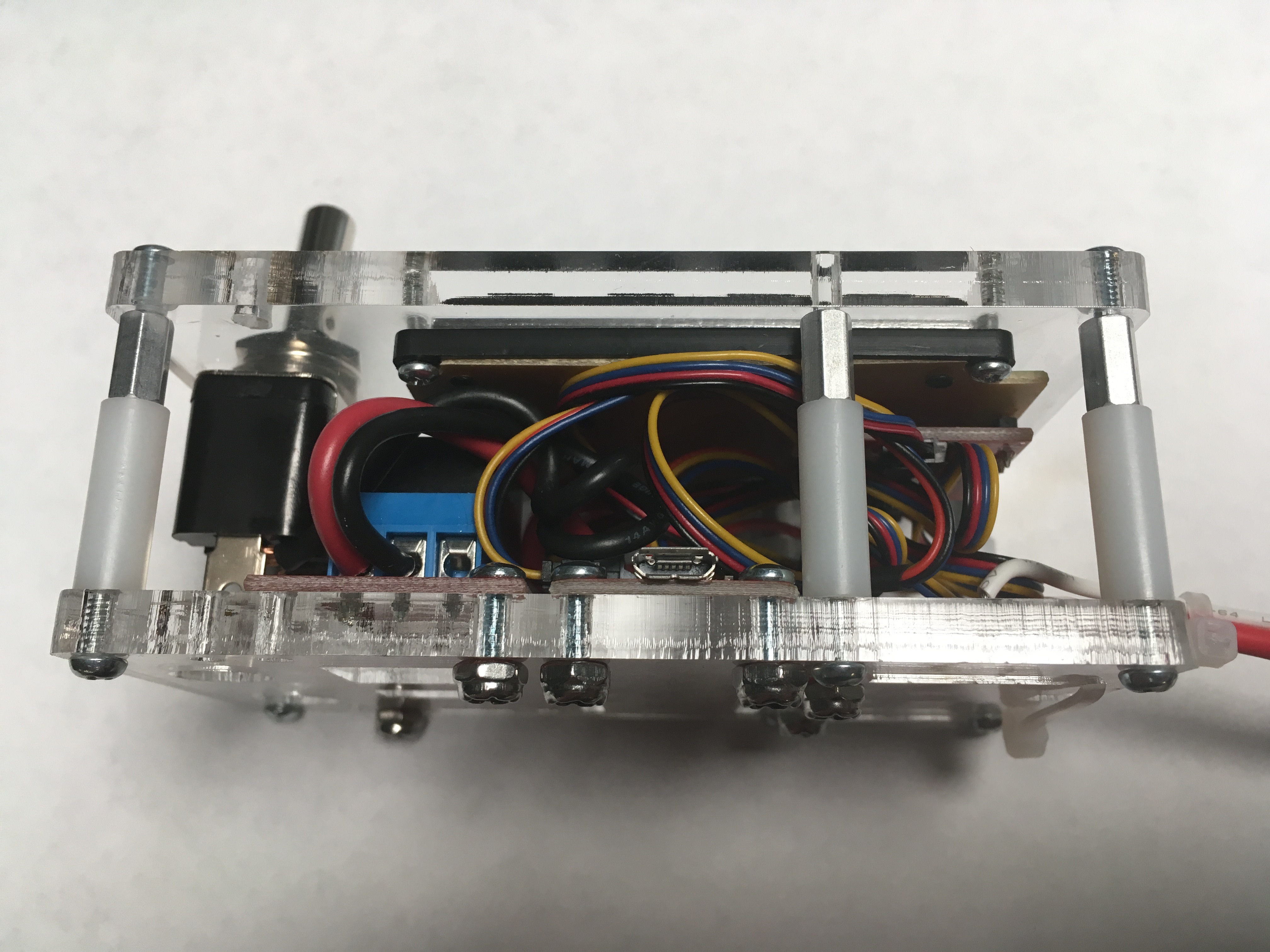
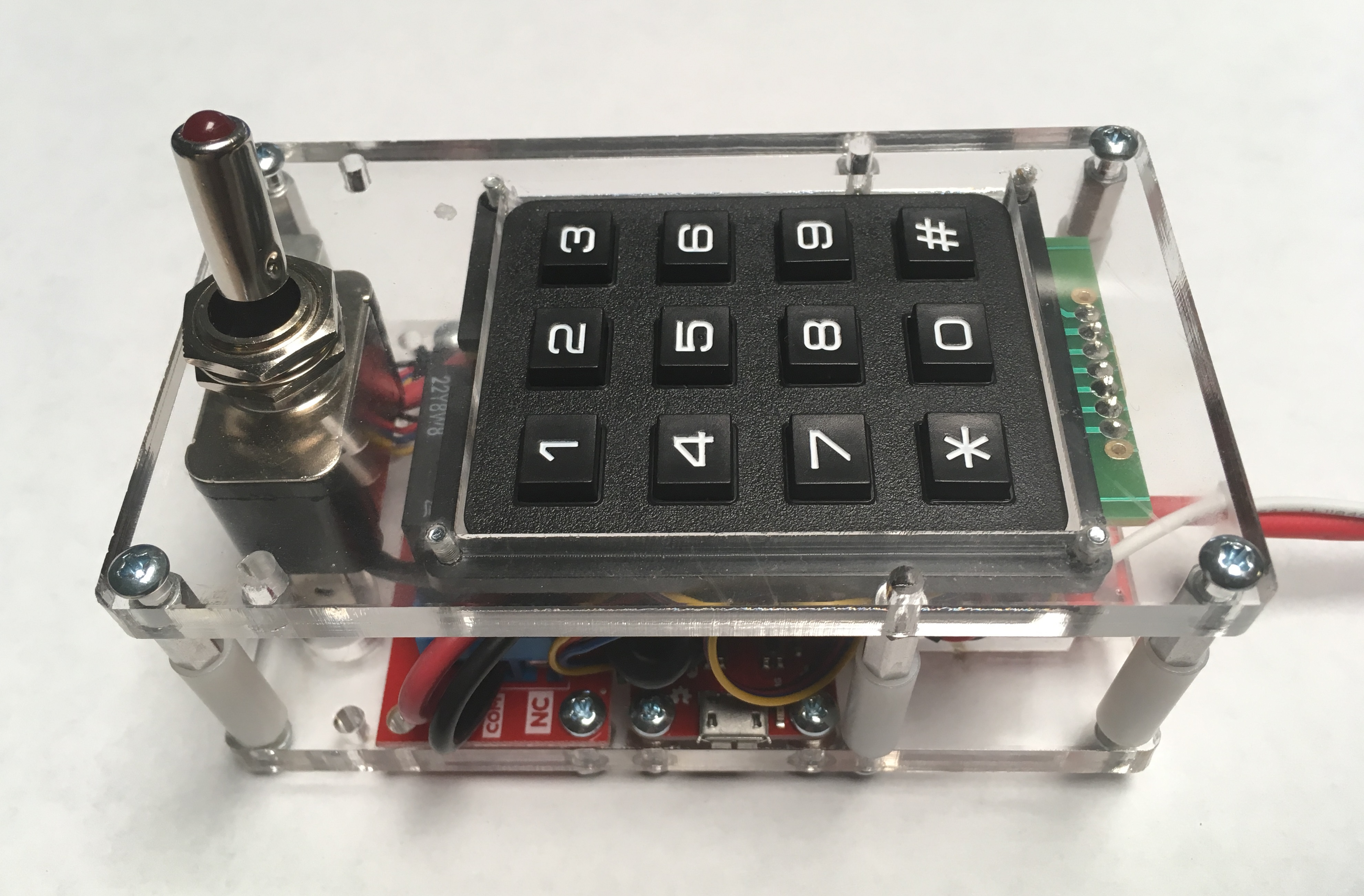
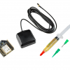
Only four cables need to be broken out of the fixture. The first two are required to power the microcontroller: a power cable that will connect to a 12V source, and a GND cable that will be connected to a body ground. The other two will span an open in the starter solenoid circuit, and can be connected via the Sparkfun Qwiic Single Relay or the toggle switch. The 12V source wire is terminated with a female spade connector to allow easy connection to the vehicle's fuse block. The body ground wire is terminated with an alligator clip, making it easy to connect to ground points all over the car. The two wires that span the starter solenoid circuit are terminated with spade connectors as well - one female and one male. Lastly, the microB USB connector of the Sparkfun Thing Plus – ESP32 WROOM is accessible through the side of the fixture, allowing easy reprogramming of the micro-controller.
I opted to use a minimum of 11 AWG cable for spanning the starter solenoid circuit; the conductor diameter in this cable is capable of surviving the amperage needed to hold the starter solenoid in place during the starting operation. As for the power circuit I opted to use a 1A fuse in series with 16 AWG cable for the 12V, and a 20 AWG cable for the body ground connections. The fuse should protect the car in the chance that any of the added components malfunction.
Stay tuned for the next installment where the security starter gets tested in the car.


