Neato Robotics XV-11 Tear-down
We tore apart a Neato Robotics XV-11 robotic vacuum cleaner and did a little reverse engineering.

On the surface, the Neato Robotics XV-11 vacuum cleaner seems like just another Roomba with a square front, but it caught our attention because of the cheap and innovative Lidar device it uses to sense the room it's cleaning. It claims to "map" the room it is in and detect doorways so that it can clean a whole room before exiting. So we went ahead and ordered one to tear-down and hack. Then on November 15th, RobotBox announced a $200 prize for the first person to post usable Lidar code. At the time of this writing, the purse is up to $800. While we don't have a usable hack (yet, muahahaha), we did a thorough tear-down and sniffed around the Lidar signals for all you hackers that don't want to drop $400 on a vacuum.
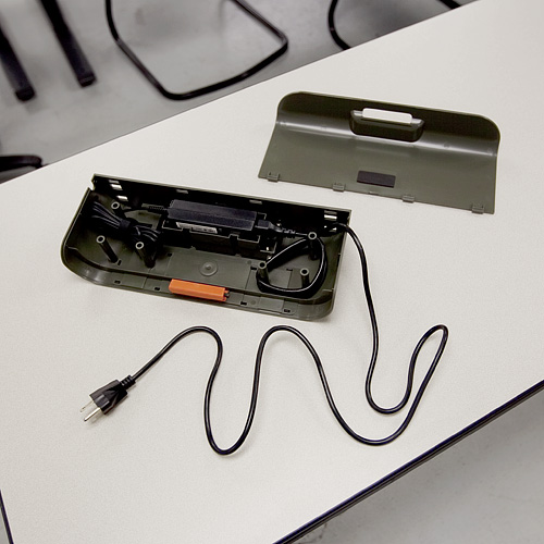
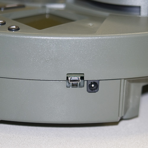
On first start up, the bot made some cutesy beep-boop robot noises and insisted that we charge its battery (the robot always refers to itself in the first person on its LCD display). So we stuck it on its wall-charging station for a while. Nothing fancy here, just a couple of spring-loaded contacts that press on the contacts on the back of the bot. However, Neato made the base charger as a simple structure for a standard power supply so the user can remove the power supply and plug it in if desired.
Once the bot was charged, we gave it a test run. The XV-11 came with a flexible magnetic strip that allows the user to "block" the bot from areas of a room, so we had a little fun laying down the strip to box the bot in. It successfully vacuumed one side of an office before we purposely confused it with the magnetic strip. When we gave it the command to return to the base station, it seemed pretty lost, and just ran into a wall and powered down a couple of feet from the charging station.
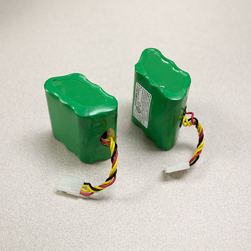
For the tear-down, we first removed the batteries from the bot. They are a couple of standard 7.2V 3200mAh Nickel Metal-Hydride cells.
After removing a couple more panels, we got down to some guts.
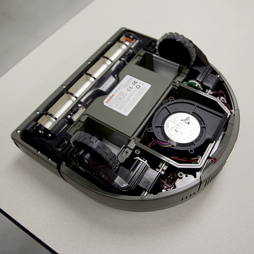
There's a suction fan, two spring-loaded wheel assemblies, and the vacuum brush. The wheel assemblies are one-piece motor-with-gearbox combinations. Each motor has a (seemingly custom) digital encoder. The axles are spring loaded and trigger a simple tactile switch to detect if the robot has been picked up (or fallen off a cliff).

Before removing the rest of the case, we poked around a bit more and discovered this:
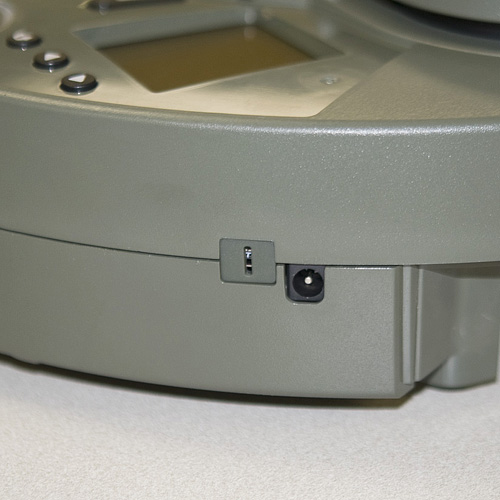
A "hidden" USB port. It's possibly for USB bootloading or troubleshooting at the factory. We also spotted the single wall sensor on the right side of the bot.
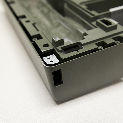
Just like a maze-bot.
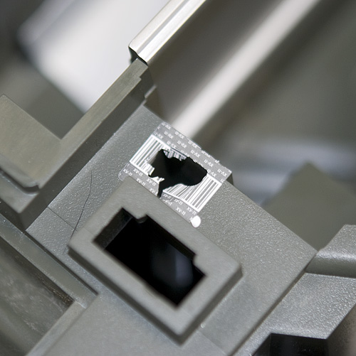
The last two screws to remove the top half of the case were hidden under some flimsy bar-coded warranty stickers. So we promptly voided the warranty.
Now we have full access to all the guts of the XV-11.
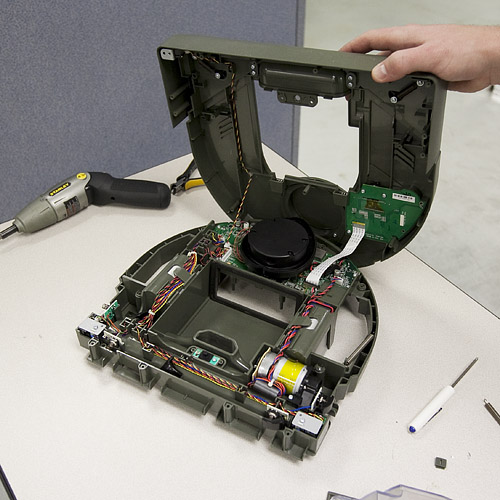
You can see the Lidar assembly sitting on top of the main processor board, the drive motor for the brush, and the daughterboard for the LCD and buttons. In the front of the bot, we can also see the optical switches for cliff detection, as well as the magnetic sensors that detect the magnetic strip. The Lidar device sits on top of the mainboard, which is controlled by a beefy AT91SAM9XE. Since the Lidar is what we're most interested in, we pulled it off first.
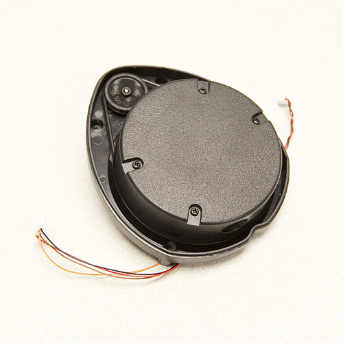
The Lidar unit is fully enclosed in a plastic "turret". It has two wires coming off of the motor that spins the turret, and four wires coming from the inner assembly. We removed the top of the turret to get a look at the mechanism.
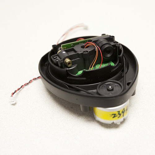
Inside you can see the laser and the CMOS imager that the Lidar uses to detect distance to objects. The white paper on this device insists that it can be built for less than $30, but right now the laser can only be bought if it's inside the robot. Still $400 dollars is a low price for a device that does 1-degree accuracy planar scanning at 10Hz. There are four wires running to the laser assembly. Upon closer inspection, we see that these wires are soldered to pads on the board labeled "TX", "RX", "GND", and "VCC". So it's not exactly tough to figure out what communication protocol the device uses.
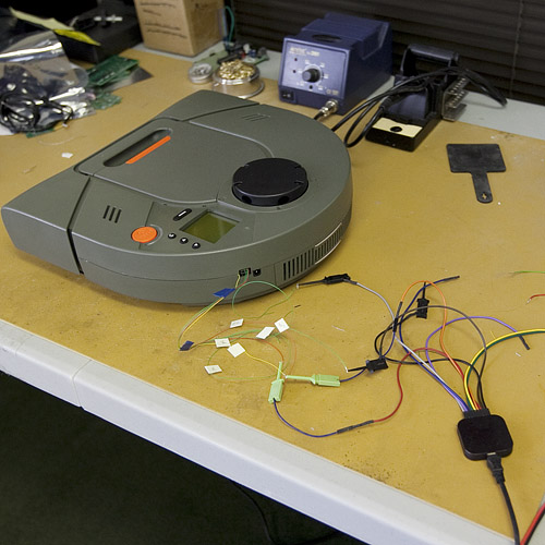
In order to start getting data from the Lidar, we soldered some leads to the communication lines and the motor lines, and assembled the bot again. We fed the lines out of the hole for the USB port on the case of the bot, so the bot should now be able to run normally while we sniff the data lines. The motor spinning the Lidar runs using a 12V square wave with a 25% duty cycle. The logic for the Lidar is at 3.3V, so we hooked up one of our logic analyzers and let the bot run.
Here's a snippet of the data that we pulled off of the Lidar while the bot was in normal operation.
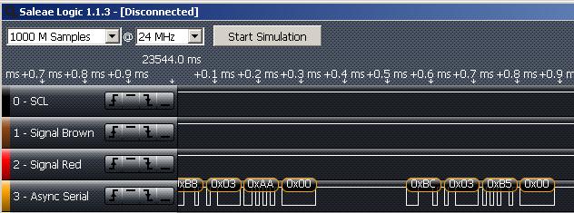
Sure enough, the TX line is spitting out data at 115200 baud. Right now, we don't know what the data means, so we conducted two more similar tests. In the first we placed a 13cm round paper "shield" around the rangefinder, so that when it runs, it should see the same distance at all 360 degrees.
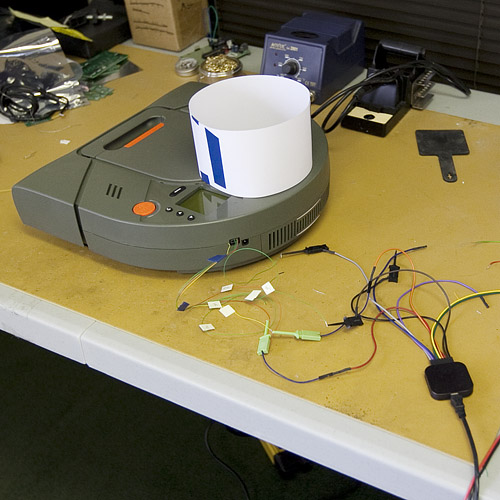
Sure enough, the bot ran for about 10 seconds, then stopped and displayed "LDS error. Visit website." We did the same test with a 22cm shield, and the same thing happened. In the logic analyzer for both tests, the Lidar spit out the same value the whole time, but different values depending on whether we were using the 13 or 22cm shield. If you are interested, here are the analyzer files for the three tests. The software for the analyzer is free online.
For our last test, we pulled the Lidar out of the bot again. This time we hooked the data lines straight into TeraTerm, reset the power to the device, and saw this
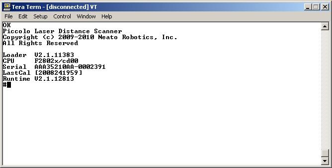
When we spin the turret by hand, the device prints the message "Spin..." and then starts spitting out data (unreadable by TeraTerm of course). We haven't got it hacked yet, but it's a good start. Hopefully some interested party can use some of this data to get some usable software going. In the meantime we're going to keep digging up data. Happy hacking!


http://forums.trossenrobotics.com/gallery/showimage.php?i=3528&original=1&c=3<br />
<br />
Does this look like what you were expecting for the "NoShiled" run ? :p
Nice plot! Sure looks right, doesn't it? Been trying to write some perl to parse out the data stream properly. Haven't verified for sure but it looked like it was broken up into 360 data point sets. <br />
<br />
Wished I could swing $400 for one of these things. I don't suppose I could borrow Sparkfun's for a couple days? :) :) :) (Boulder is a pretty short drive... :))
Hm, this brings to mind an interesting new sales model:<br />
<br />
1. Create a product retailing for $400 with interesting technology bits inside.<br />
<br />
2. Put up $1000 bounty to the first hacker to do X with embedded technology.<br />
<br />
3. Sell lots of units to aspiring hackers.<br />
<br />
4. Profit! :-)
You mean like Robosapien?
Can you guys dump the teraterm output from the 13mm and 22mm to a file and post it?
Also, Can anyone post the speed at which it takes the unit to make a complete revolution?
The published specs are that the unit rotates at 10 hertz.
10Hz 360 dgerees for $30 , 2014 thats not here yet
Does anyone know if there's a circuit diagram floating out there of the LIDAR system I can look at?
Has anybody tried to turn the LRF on its side to see if it operates in that orientation?
Well done, Hash79: http://robotbox.net/blog/gallamine/neato-robotics-xv-11s-lidar-hacked
Video showing live data processing and the python code used.<br />
<br />
http://random-workshop.blogspot.com/
Check out this data dump and explanation. Significantly different from what was seen at Sparkfun.<br />
<br />
http://random-workshop.blogspot.com/2010/11/useable-data-from-xv-11-lidar_25.html
Pics of test setup and Terminal interface into the XV-11 LIDAR unit.<br />
<br />
http://random-workshop.blogspot.com/
http://www.youtube.com/watch?v=vneaaKsa2Dw<br />
Code : https://github.com/Xevel/NXV11<br />
If anyone with a hacked robot could test the code with real live data... :puppyeyes:<br />
Looks like four bytes with data straddling bytes (well to a degree) - little endian style. From the looks of it - there is a header of some sort (6bytes - 5A A5 00 C0 xx D1) - the xx seems to be a byte which changes. Then following this is 360 samples - these are composed of 4 bytes each and yes, appears that based on timing from traces - scanner runs at 5Hz. Details of each sample appear to be something like the following:<br />
<br />
- Byte 1: Lower Byte of Distance Measurement<br />
- Byte 2: Top 7 bits are status info bits - MSB seems to indicate reading not possible. LSB seems to be part of the distance measurement and is the 9th bit of this value with the 8 other bits being represented by Byte 1. <br />
- Byte 3: Lower Byte of Quality measurement (reflectance etc - who knows) ??? <br />
- Byte 4: Upper Byte of Quality measurement (reflectance etc - who knows)???<br />
<br />
What would be most useful is a square box around the device as previously mentioned or putting it in a square room - to get a better feel for the data structure - seems like the current no shield data has too many issues for really solid proof of the above description.<br />
<br />
Hope this helps!
From the pictures of the turret on Robotshop and here it does not look capable of spinning in one direction forever. Are the 4 wires coming off of the spinning mechanism just going through the center and out the bottom?<br />
<br />
Have you seen the turret spin in one direction continuously? The white paper on this device talks about a low range RF link to transfer data but I would say due to cost (and the extra complexity in the prototype pictured) they dropped that idea and possibly decided to rotate the turret one way 360 degrees and back the other way 360 degrees. Maybe this is data in the stream that is transmitted.
Nevermind, I think I can see the slip-ring in one of the pictures.
Anyone willing to divulge or speculate what imaging sensor is being used? Am really curious. (But not $400 curious) :D<br />
<br />
@Otatiaro: we're getting similar results - 5hz spin, etc.
Otatiaro: Hello,<br /><br />
<br /><br />
Extracted this "radar" from the data flow ...<br /><br />
<br /><br />
http://otatiaro552.free.fr/radar.png<br /><br />
<br /><br />
Turret was spinning at 5Hz (at 1.7 to 2.0 seconds).<br /><br />
<br /><br />
Regards,<br /><br />
Thomas.<br /><br />
<br />
I used the data flow with shield.<br />
without ... sorry
Hint : the variables are 10 bit wide.
Distance seems to be at least 12 bit...
Hello,<br />
<br />
Extracted this "radar" from the data flow ...<br />
<br />
http://otatiaro552.free.fr/radar.png<br />
<br />
Turret was spinning at 5Hz (at 1.7 to 2.0 seconds).<br />
<br />
Regards,<br />
Thomas.
Can you please post more logs with ranges that are >.2m in radius? The white paper states that the sensor has resolution from 0.2-6m. So the data posted isn't good for hacking with..
just looking at the post here, and im rather simple minded, im seeing "data start -- data type -- data -- data end"<br />
the data being a 2 char hex (8 bits) and thus 0 to 255, it makes sense this corresponds to some other pre-coded unit of measurement. <br />
Also off a simple dc motor, how is it detecting what angle its at? hall effect and an assumed rpm? more encoding?
So my knee-jerk thought was to take the smaller diameter roll, cut out a vertical slot that would equal a defined angle at that distance; then put the larger diameter roll outside it.
Replace the circular shield with a square one. This will give you a range of readings that you can compare mathematically. For example, the maximum points might all be at 90 degrees, with the minimum ones offset by 45 degrees. The readings in between might fit with what you can calculate. This could possibly give you readings of angles and distances.<br />
<br />
Assuming it's that simple. ;)
Does Sparkfun have any resident programmers on site? You could read the serial data into a computer program written to parse the hex data after the word "spin" and plotting out the numbers.<br />
You might even be able to copy/paste the hex data into excel and parsing it with VBA, or use the serial input API from within VBA itself to capture and extract out the data.
Well, this site didn't magically appear, and neither did any of our internal software tools :)<br />
That said, we're pretty swamped at the moment, but I'm sure one of us could do it some other time as it shouldn't be very difficult at all. You won't find us using any .NET tools, though.
As an addendum, you could hook an xbee module to the robot and a matching xbee module to a computer and let the robot roam around while the computer extrapolates data.<br />
Just hang an LD33V off the robot's power supply, an xbee module off of that, and Robert's your father's brother.
For sending/viewing hex I've found the Hercules SETUP utility from the hw-group to be very useful. Can download for free here: http://www.hw-group.com/products/hercules/index_en.html <br />
<br />
I use it all the time for testing RTUs and PLCs that don't use ASCII command sets.
Thanks SF for sharing this exciting quest. I can see some use for the lidar, but mostly appreciate the insight in the general hacking process (as in, it gives me confidence to open up anything anyone will put under the xmas tree ... for anyone). Planet beware !
It's a shame the XV-11 is not available outside of North America...
CTaylor,<br />
Awesome! I run RobotBox and was the one that put up the initial $200 bounty. Others from the community have chipped in to raise it. On Friday, the CEO of Robodynamics offered $200 to the first person that used the sensor with a SLAM algorithm for mapping: http://twitter.com/robodynamics/status/6109560045572096<br />
<br />
That means there's now $1000 you can potentially win from hacking this thing.<br />
I'm really stoked by the response and hope it'll be a valuable sensor.
Hindsight is always 20/20, but if you're using the saleae analyzer it should be configurable to show ascii rather than just hex, so that could have been used rather than teraterm since you had it hooked up first.<br />
<br />
Also maybe the unreadable text after "Spin..." is coming out at a different baud rate?
If you look at the whitepaper linked in the article, and at the dumps, the unreadable text looks to be raw samples in binary. The system reports its system parameters in human readable form then switches to binary because it needs the data speed to get 3600 sps.
The initial ASCII text is only sent when the device reboots. The data after "Spin..." is data coming from the sensor. It's still being sent at 115200, but it's hexadecimal sensor data, and not ASCII, so on Tera Term it looks like junk. We used the logic analyzer to view the data hex values, which is what we're interested in.
I cannot wait to make a cheap mapping robot using this sensor. Neato said they would make spare parts available in a few months. (Those wheels look nice too)
Actually, when I was doing the tear-down, I was surprised at how nice the wheel assemblies were. They seem very solidly built, no skimping on heavy-duty construction.
it remenbers me about adafruit and that hackering kinect stuff... the prize, the data sniffing, etc...
tiagofumo,<br />
Yeah, I was inspired by Ladyada to sponsor this contest.
Looks like its running a TI TMS320F2802. <br />
<br />
http://focus.ti.com.cn/cn/lit/ds/symlink/tms320c2801.pdf<br />
<br />
You might be able to get a flash dump from the DSP on the LIDAR unit if you can get at the JTAG lines.