- Home
- Product Categories
- IMU
- SparkFun 6 Degrees of Freedom IMU Digital Combo Board - ITG3200/ADXL345

SparkFun 6 Degrees of Freedom IMU Digital Combo Board - ITG3200/ADXL345
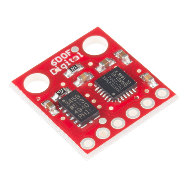
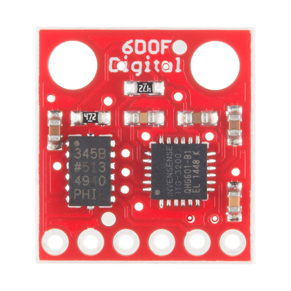
This is a simple breakout for the ADXL345 accelerometer and the ITG-3200 MEMS gyro. With this board, you get a full 6 degrees of freedom. The sensors communicate over I2C and one INT output pin from each sensor is broken out. If you need a simple and tiny board that gives you 6 degrees of freedom, this would be a good choice.
Having a hard time picking an IMU? Our Accelerometer, Gyro, and IMU Buying Guide might help!
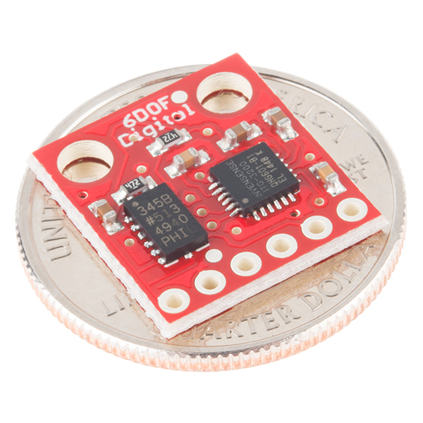
- Tiny!
- Two mounting holes
- ADXL345 accelerometer
- ITG-3200 gyro
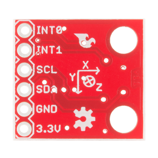
- 3.3V input
- I2C interface
- [Schematic](http://cdn.sparkfun.com/datasheets/Sensors/IMU/IMU_Digital_Combo_Board -_6_Degrees_of_Freedom-ITG3200-_ADXL345.pdf)
- [Eagle Files](http://cdn.sparkfun.com/datasheets/Sensors/IMU/IMU_Digital_Combo_Board -_6_Degrees_of_Freedom-ITG3200-_ADXL345.zip)
- Datasheet (ITG-3200)
- Datasheet (ADXL345)
- bildr Tutorial
- GitHub
SparkFun 6 Degrees of Freedom IMU Digital Combo Board - ITG3200/ADXL345 Product Help and Resources
Core Skill: Soldering
This skill defines how difficult the soldering is on a particular product. It might be a couple simple solder joints, or require special reflow tools.
Skill Level: Noob - Some basic soldering is required, but it is limited to a just a few pins, basic through-hole soldering, and couple (if any) polarized components. A basic soldering iron is all you should need.
See all skill levels
Core Skill: Programming
If a board needs code or communicates somehow, you're going to need to know how to program or interface with it. The programming skill is all about communication and code.
Skill Level: Competent - The toolchain for programming is a bit more complex and will examples may not be explicitly provided for you. You will be required to have a fundamental knowledge of programming and be required to provide your own code. You may need to modify existing libraries or code to work with your specific hardware. Sensor and hardware interfaces will be SPI or I2C.
See all skill levels
Core Skill: Electrical Prototyping
If it requires power, you need to know how much, what all the pins do, and how to hook it up. You may need to reference datasheets, schematics, and know the ins and outs of electronics.
Skill Level: Noob - You don't need to reference a datasheet, but you will need to know basic power requirements.
See all skill levels
Comments
Looking for answers to technical questions?
We welcome your comments and suggestions below. However, if you are looking for solutions to technical questions please see our Technical Assistance page.
Customer Reviews
3.8 out of 5
Based on 4 ratings:
Pleasant surprise
We bought two IMUs and both of them performed much better than we expected. Great value for the price. Sample code was very helpful as well.
Works well!
Very easy to use; just follow the data sheets of the accelerometer and gyro.
Works good
Works good I like it. Connected to an Arduino, simple and done.
OMG the YAW
Drifts like crazy :(
Shoot our Tech Team a email, they can help determine if this is a issue with the sensor. Thanks
Hi ! What is its size please?
I've been playing around with this with the Netduino, and have successfully pulled data from both the gyro and accelerometer. Both require values written to key registers before they'll return data. I've put up some quick notes here.
Hey guys,
I tried to look through the linked github site but was uncomfortable using the C files with my arduino files. I looked around to see if someone had done this in processing/Arduino and found this man's site:
http://www.varesano.net/blog/fabio/my-first-6-dof-imu-sensors-fusion-implementation-adxl345-itg3200-arduino-and-processing
I had my sensor up and running in very little time, the only change I needed to do is set the serial port used in his processing code to the one listed under the 'tools' tab in Arduino. Also note that he changed the baudrate to 19200 in the on-board version of the code.
And out of curiousity, could someone point me to a tutorial that tells me where to put all of the files given on github and how to make them?
-Stefan
Thanks for the link! I'm able to get accel and gyro readings, no problem. Wouldn't have been able to since I'm not familiar with I2C. Sparkfun should post some tutorial or documentation to use this board.
For some reason, the serial print with the str variable in the code was not working, even at 19200 baud. I just replaced it with individual print commands for all the readings.
This product looks great, and I'm sorely tempted to get one when it is back in stock. Any thoughts on incorporating the HCM5843 (three-axis magnetometer/compass) and having a board with all three sensor types in digital I2C style? I feel like this would be the ideal way to do off-board processing of IMU data, since the I2C interface minimizes the wiring issues, and allows the board to be positioned away from sources of noise like PWM generation. This would be a bit like the 9DOF Razor I suppose, but without on-board processing or the need for an analog interface.
I've been debating picking up the 9DOF AHRS board for a while, but I want to interface with an XMOS board, and I'd much rather do the filtering on that. An all-digital sensor solution with plain I2C would be ideal for me.
Has anyone had success connecting 2 boards to an arduino? If so, what is the most efficient way of doing so?
some basic example?
So, can i also use this board to get more than rotation? Like, movement in space (translation)? Or is this IMU only good for the former? I am trying to make a Glove which knows how the hand is rotated and where (or which direction) it is moving
i got a question about this IMU, well i bought this UMU last month and everything seems to go on its way, but i notice that for some reason, the imu invert the X axe positive and negative values in some moments, i mean , sometimes i lift up one side and its says that is a positive value, but sudently it says its a negative value, and i don't understand why it has to invert the positive and negative side !...
i got a question about this IMU, well i bought this UMU last month and everything seems to go on its way, but i notice that for some reason, the imu invert the X axe positive and negative values in some moments, i mean , sometimes i lift up one side and its says that is a positive value, but sudently it says its a negative value, and i don't understand why it has to invert the positive and negative side !...
Hi I'm currently doing a project in which I need an IMU-board to measure the angle of elevation of a ball when it is thrown in the air. I was just wondering if this IMU board is bluetooth compatible? (or any other wireless transmission module). If not what would you recommend? Hope to hear from you soon. Thanks
if i'm compiling d code i'm getting d error //////////////////////////////////////////////////////////// // Arduino firmware for use with FreeSixCube processing example ////////////////////////////////////////////////////////////
include <FreeSixIMU.h>
include <FIMU_ADXL345.h>
include <FIMU_ITG3200.h>
define DEBUG
ifdef DEBUG
include "DebugUtils.h"
endif
include "CommunicationUtils.h"
include "FreeSixIMU.h"
include <Wire.h>
float q[4]; //hold q values
// Set the FreeIMU object FreeSixIMU my3IMU = FreeSixIMU();
void setup() { Serial.begin(115200); Wire.begin();
delay(5); my3IMU.init(); delay(5); }
void loop() { my3IMU.getQ(q); serialPrintFloatArr(q, 4); Serial.println(""); //line break
delay(60); }
Pls help me to debug d error thanx in advance
Correct ITG-3200 Datasheet Link: https://www.sparkfun.com/datasheets/Sensors/Gyro/PS-ITG-3200-00-01.4.pdf
Hey, I've got a problem. I use a PIC24 to communicate with this IMU board. I can get the right result from adxl345, but cannot get the right output from itg3200 and always get 0 when i try to read the internal registers of itg3200. I tried two boards, they are the same. I have no idea what is going wrong.
hola soy de colombia y mañana un amigo viaja a miami y necesito contactarme con ud para la compra de este sensor, espero su numero telefonico y direccion gracias
I followed the basic bildr tutorial. My board appears to hang when it calls the sensor library's init() method. Anyone know what that's about? Thank you!
Hi ... I am using the ADXL345, worst I need to find the angle between the horizontal and the floor, I read the datasheet and APPLICATION NOTE but does not answer an answer coherenteen degrees ... I would greatly appreciate if you can help
i use this product for my final year project....i use pic18f452...the problem is i was try many times...but i don't get the result...i use microc pro to write the coding...anyone can help me...
Hi to all, Have anyone used MATLAB and Simulink arduino support package for implementing this IMU? If so, could anyone detail me how to use them. Thanks in advance.
I just got a product, but I have a problem. I tried with Bildr sample. It seems like link and everything work right, but the data printed only "77917F3F,00000000,00000000,00000000, 77917F3F,00000000,00000000,00000000,
.. Is it problem of the product itself or connection?
Hi, I would like to know the supply current of the module. I looked at the documentation and the ADXL345 has a supply current of 145uA (when the data rate is bigger than 100Hz) and the ITG3200 has 6.5uA.*
Do I sum this results or do I consider the biggest?
I'm having issues getting this board to work with an Arduino Pro Mini 3.3v 328. I am following the bildr tutorial exactly as it is linked above but instead of using an uno I'm using a pro mini 3.3v. I'm using a digital pin set to HIGH to power the 6dof board.
I just purchases two of these and they work really well with my arduino UNO so I know the 6dof's are working just fine.
Can anyone help me or point me in the right direction? I'm new to the forums here so I'm sorry if I'm posting out of place.
Thank you for any help!
If I'm interfacing this with a 5v micro controller, then I would assume that you needed a level shifter on the i2c lines, but the bildr tutorial doesnt do this. Any help?
Does anybody know a method that I can use to test if my board is working. I have tried using multiple different sketches with an arduino such as the bildr tutorial, but none of them seem to be working. I have tried hooking it up to power, and then looking at the SDA line with an oscilloscope. I get something that looks like a sine/triangle wave. However, nothing changes when the board moves. Do I have to hook up the SCL to something? Any help would be appreciated.
Both SDA and SCL need to be attached to your host in order to get anything to work. Try the tutorials again with both of these lines connected (the tutorials should have this information), and hopefully you'll have better results.
Hi guys, I bought the IMU Board in combination with an Arduino Pro Mini and have tried a number of demo-programs now. The gyroscope is working quite good also with a visualisation in processing. The problem is that i dont get data from the accelerometer. The serial monitor just shows me -512,-512,511 and does not change. Does anyone have an idea what the reason for this could be?
I just got this sensor and I had been having a horrible time in trying to get it to work until I found this website here: http://bildr.org/2012/03/stable-orientation-digital-imu-6dof-arduino/ They have modified varesano's library to work with this sensor and it is as simple as two lines of code to get extremely accurate measurements out of this sensor. They have a simple example that anyone could understand and then implement in their own device. I'm building a segway and this sensor was just what i needed, an accelerometer and a gyro.
Hello, I have followed the bildr Tutorial word for word, except when I open the serial monitor, the values are all 0.00. These do not change over time, nor with movement. Does anyone know what to do?
do you have two resistors hooked up also? the bildr tutorial does not state that. you need to 2.2k going from the 3.3 to both the sda and scl lines.
I see that this board is listed as an IMU, but could anyone tell me if it could be used for INS purposes? Or in particular could it be used to determine when a device is in motion as well as when it has stopped moving? thanks.
i hooked up my ITG-3200 using this tutorial but i am not getting any response from the gyro (Wire.available is never >0) the function simply returns 0
why is there no wire leading to the ground pad in the schematic???
All the GND wires are connected (and all the 3.3V are connected, and all the SDA are connected, and all the SCL, ...). You do not have to draw the wire - this is just a convention to make it easier to read the schematics.
The ADXL345 datasheet recommend the minimum of 1uF capacitor between Vs and GND (pg 19). Why the board has only 0.1uF one?
Got this working using the bildr tutorial very fast with the visualization. It looks great at first but has constant drift when secured to a table... yaw drifts at -1 degree per second, pitch at around -.1 degree per second, and roll at about .1 degree per second... is this normal? This pretty much makes it worthless except for very short term motion changes.
Hi, did u found a solution on the drift problem?, i'm now using one of these to replace ipad control but i have the same issue, there's no way to calibrate it lik ethe one used at this tutorial? - https://vimeo.com/32898673.
regards.
In re. to member#318547, yes, gyro drift is normal and can never be fully removed. The solution to correcting for some of the drift is augmenting hardware (like a magnetometer for yaw compensation) and some nifty math in software. It is not easy and it looks like the bildr code does something in the Kalman filter, but you really need another sensor to correlate. In the video link, that board uses a magnetometer and AHRS code as well. The board you need is this one.
Actually, the Invensense (ITG-3200) gyros are some of the most drift tolerant gyros we can find, so the drift you see is actually relatively good for the type of sensor on this board.
Thank's a lot for the reply, and yes for future development that stick should be my first option; but now that i buyed the product on this page and make permament connections with it, do you think that i could use it for real world applications?, maybe just trust on its accelerometer for wii like controls?. What do you think?
regards.
Not sure what you are asking, but if you want to compensate for drift, you will need another sensor like this one. Otherwise, you will have to deal with the drift in software.
quick question: why was an external clock source for the ITG left out?
Will this product (and obviously some more arduino related parts)enable me to work on this awesome project:
http://www.youtube.com/watch?v=7GVXqNLLH7Q&feature=youtube_gdata_player
Needles to say it seems advanced coding to a noob like me, and yet I'm thinking of grabbing the parts and entering this adventure... :)
Anyone know what the spacer length and diameter should be if I want to plug this into a standard female header soldered on my board. More importantly, where can I find them?
Thank you, Mike for your reply. I will try this tonight. the only thing is that in that example they connect SCL and SDA to analog inputs and didnt use Int0 or Int1 pints. Do I need to get that wired to the Arduino as well?
Guys, I just got my 6DOF ITG3200/ADXL345 and I am trying to make it work with Arduino Uno board. All I got in my serial monitor is a scrolling 1023 number. I am a very new at this, so please help. I connected 3.3 ref voltage and 2 resistors 4.7k connected to the SDA and SCL pins on the sensor. I've read here that some guys were talking about addressing 0xDO and so on... but I dont know where to change it. Is it something on the Arduino controller board? please help. Here is the program I use in Arduino. I tried differnt pin outputs in the program with the same result. // Arduino - Analog 3.3v Accelerometer // Connect accelerometer output into Arduino analog pin 0 // Upload, then open Serial monitor at 9600bps to see accelerometer value int angle = 0; // variable used to hold the "rough angle" approximation void setup(){ Serial.begin(9600); // start Serial monitor to print values analogReference(EXTERNAL); // tell Arduino to use the voltage connected to the Aref pin for analog reference (3.3v) //– remove this command if you are using a 5v sensor. } void loop(){ angle = analogRead(1); // read the accelerometer from Analog pin 0 Serial.print("Accelerometer: "); // print the word "Accelerometer: " first Serial.println(angle); // then print the value of the variable "angle" delay(100); // update 20 times per second (1000 mS / 50 mS = 20) }
The ADXL345 doesn't have an analog output, which is why your code isn't working. Both of the parts on this board have digital I2C interfaces (they're on the same bus but have different addresses), so you'll need to use the I2C interface to "talk" to those parts and request data back.
A good tutorial on talking to the ADXL345 is available at Bildr: http://bildr.org/2011/03/adxl345-arduino/. Don't worry that it's a different board, connect to the same-named pins and you should get results. Once you have the ADXL345 working, google for examples for the ITG3200, which will be very similar. Once you have both working separately, you can merge the two examples together and get one piece of code that talks to both sensors. Good luck!
Thank you, Mike for your reply. I will try this tonight. the only thing is that in that example they connect SCL and SDA to analog inputs and didnt use Int0 or Int1 pints. Do I need to get that wired to the Arduino as well?
Don't worry about the INT pins, they aren't needed to take measurements (they're a special feature that allows the ADXL345 to detect falls, taps, etc.) The only pins you'll need to connect to your board are SCA, SCL, GND, and 3.3V. SCA and SDL do go to analog pins, which is confusing, but internally the Arduino uses those pins for multiple purposes; both as analog inputs and the (digital) I2C port. I hope this helps, good luck!
Thank you, I got it working. But how do I use that gyro chip ITG-3200. they both share the same SDA and SCL pins? Do I need the line in the code somewhere to specify which chip to use? Sorry for all these stupid question :-)
We have a tutorial for connecting an Arduino to the ITG-3200. Again it's for a different board, but use exactly the same connections as you did for the ADXL345 (they do share the SDA and SCL pins) and it should work fine.
One thing that may be a problem is that the above tutorial was written for Arduino version 0.22, but it will have errors in Arduino 1.0. If you're using an older version of Arduino you don't have to change anything. If you're using a newer version of Arduino, change anywhere it says "Wire.send" to "Wire.write", and change anywhere it says "Wire.receive" to "Wire.read".
Thank you, I got it working now. Another question is how do I display a tilt angle? I have X, Y, Z values I can read and display. but I need to co-relate these number to the tilt angle to have my motor to compensate. I am looking for a 0-1023 No (10 bit output) with -90 degree to 90 degree tilt respectively or 511 value set as 0 deg.
I appreciate all your help.
VERY URGENT QUERY : I would be using a 3.3 volts regulator while interfacing this IMU to the Wiring board which would be running on 5 volts. But the SCD and SCA logic pins of the IMU would be connected directly to the ports of the wiring board. Is it possible that they might be exposed to 5 volts directly from the wiring board and IMU may burn out ?
Hello commenters and staff,
I am interested in knowing the official sampling rate of this device over i2c. Namely, how often I can poll and fetch gyro/accel readings from an i2c master device.
The datasheets and description all claim "400khz" using the i2c interface. However, using an Arduino Mega 3V3 and simply polling the accel/gyro and pushing the data to PC, I get 50-90Hz (that's HZ, not KHZ) at maximum. 40-90 accel/gyro readings a second is not remotely enough for any IMU capability (papers and research I find claim 300HZ as a minimum).
Can anyone give me the info on the ACTUAL maximum sampling rate of this device or recommend another product which can work as an IMU with sample rates of 300Hz or more? What is the reason this device is limited to such low sampling rates if the devices (ITX/ADXL) support samplerates of 1kHZ or more as their datasheets claim??
I have this module talking to an NXP LPC1343 at up to 1600 samples per second. You need the I2C bus running at 400kHz to achieve this sort of sampling rate. I suspect your issue is the Arduino Wire library. For some reason this sets the clock rate to 100kHz. See the following forum post for how to change http://www.arduino.cc/cgi-bin/yabb2/YaBB.pl?num=1241668644.
My code also reads all 6 byte blocks from each of the sensors in a single I2C transaction. This is much quicker than 6 I2C calls which is what some of the code I have seen does.
You might also have some issue with serial baud rates. I had to push up to 500000 baud to get enough bandwidth to push all data to the PC.
A CRO is really helping in tracking down what is happening here. Set a digital output at the start of the sensor read routine and clear it at the end. You can then tune the I2C settings to get this to the correct rate.
I am trying to get an ArduIMU to control a Quadrotor, but most of the comments I read complain about the sample rate (less than 100 Hz). Is there a similar modification in the ArduIMU so I can get at least 200 Hz ?
Thanks.
hi guys, just want to ask if this board http://www.sparkfun.com/products/9268 is the same with digital board? i have found a code for the analog 5DOF imu but the IMU is out of stock already so i decided to buy this, my question is does the code will work the same if i apply to this IMU board?
Can someone help me out? I'v been trying to get this sensor to work for a couple days now, but none of the code i have found worked. I'm new to i2c and would appreciate it allot if someone could help me get my sensor to work, thanks!
Okay i had a little success with the board, i got it to work with freeIMU, both sensors. But i am having a weird problem, anywhere from five seconds to one minute into working the serial print stops. I tried to put pullup resistors on and then a logic level converter but nothing seemed to work. Has someone experienced similar problems?
Can this product be used with Arduino without any additional TTL voltage level converter? If not, is there any reference design / product that can be used inbetween?
Yes, no converter necessary. Arduino's Wire library properly handles this (the port pins are never connected to 5V, and the logic thresholds will accommodate 3.3V input). Just be sure to power the sensor(s) from 3.3V, not 5V.
I know you posted this comment a while ago, but can you elaborate? My understanding is that the Wire library does explicitly use the internal pull up resistor on the data and clock lines (I've seen quite a lot of posts suggesting this, and some examples showing of to modify the twi.h file to get around it). Is it something that was changed recently ?
I'm using a 5.5V processor for ease of servo signals, but would really like to use this board. If I put a 3.3V regulator on the power line and some resistor on the SDA and SCL lines to pull the voltage across the chip down, it should work, right? If so, what value resistor should I use? I can't simply measure the resistance from those lines to ground and use an equivalent resistor, can I? Before I start trying different resistors and trial-by-error, what sort of damage would over-volting the comm lines do? Thanks!
Can this board support 5v signals?
I have to admit that I am not that great with electronics. I have one of these boards and an FTDI breakout. I am trying to send a signal to my laptop to get xyz coordinates on a platform. Is there a way to wire the two boards together and communicate directly to the PC, or do I need something else between them?
Please help?
/
Does somebody have some example programs for this module? I am using the avr ATmega324. Can someone explain how to get the accelero and gyro values?
i have a question about IMU 6DOF Razor - Ultra-Thin IMU is the same
IMU Digital Combo Board - 6 Degrees of Freedom ITG3200/ADXL345 or better IMU Digital Combo Board - 6 Degrees of Freedom ITG3200/ADXL345 ?
thanks a lot mexico
I just received the board, is there a way to test that it is working?
From the schematic, there seems to be pull-up resistors. So can i say that the sda and scl pins will output a "high" the moment i feed in 3.3v and gnd?
Can i measure the the scl and sda using a multimeter to verify that it is working?
hi, have you succeed testing this IMU?
btw, what is the weight of this IMU?
Thanks.
You are probably going to need a microcontroller to test this. or maybe a scope. I don't think you can (easily) do it with just a multimeter.
If sparkfun runs out again ...
wii chuck adapter + wii nunchuck + wii motion plus = $16
or basically the same thing
okay, address question - in the schematics, there is a read address and a write address for both the accel and gyro, but the code examples, only one address is being used - is there some byte magic happening here.
this is the way i understand it... if you would want to send data to either chip, you would send it the the 'write' address, give it the register address, then the data to put in the register. if you would want to read from the chip, you would supply the read address, the register address and ask for a certain amount of bytes, ie 6 for the accel (x,y,z * 2 each, for int) ??
or something i dont understand?
any help is appreciated - thanks.
follow-up.... bad solder joint. the 7bit address is the one to use with the wire library.
ITG-3200 seems to work fine. But the ADXL345 accelerometers are showing only 0's. I try to set it to measure by setting reg 0x2d to 0x08 but when I read the register again it's value is still 0x00. The device addresses confuse me: 0xd0, 0xd1, 0xA6, 0xA7?
Ok, so I think I figured out the device address issue. The base address + R/W bit was confusing since NETMF adds it automatically. But the acc is still reading 0 0 0. It seems I can't set power ctl reg to Measure!
Is there any way to connect two of these to one Arduino? If the I2C addresses of the gyro and accel are fixed and not possible to change, it might be difficult/impossible to read from two boards separately? Is there a way to have two different I2C busses on one Arduino like it is with hardware serial and software serial?
Since I2C was designed from the start to connect to multiple devices, whereas serial is generally used to connect to only one device, there isn't the same demand for a softi2c library as there is for newsoftserial. This isn't to say it can't be done, but it would take a fair amount of manual port fiddling.
There are two easier solutions I can see. One is to modify the board (or make a new board) to use the alternate addresses available on each of the sensors (see the datasheets). This board wasn't designed for this, so you'll need to look at the layout and see where you'd need to cut traces, etc. Another approach would be to dedicate a second Arduino (such as a Pro Mini) to the second I2C channel, and have it bridge data to the main Arduino using newsoftserial, etc. Hope this helps, good luck with your project!
i have a simple question... in my project i use all the interrupt pins available but i need to add this sensor to. Do i need to use INT0 and INT1 pins to get data from the sensor?
No, the INT pins provide special features such as tap detection that you don't need if you just want to read data. See the datasheets for more information.
Hi, since i'm a newbie i have a maybe stupid question, can i connect the board with pins without soldering it?
Soldering is highly recommended. There are enough factors involved in getting parts like these working, that a flaky connection isn't something you want to add to the mix.
You can use Solderless Headers.
Anyone know when this will be back in stock?
Hi and thanks everybody,
I'am new with i2c and I dont succed to make this IMU board works...
I use the logic level converter to connect it to and arduino decimilia.
I'm not sure of my schematic and of the program I use ! So do you know were I can find a good tutorial for both problem ?...
Thanks by advance
I soldered the sparkfun HCM5843 breakout board onto this one to create a 9DOF sensor and i'm having some serious, what seem to be capacitive, issues with the ITG-3200. I'm using the MSP430F2274 and my code can run endlessly communicating with the other two sensors. I can get data from ITG-3200 from anywhere between 1 and 20 secs and then it freezes. Logic analyser shows that the ITG-3200 is just sending back a nack in response to a read. This happens when it is just lying on the table but when i go to touch it, nine times out of ten it will freeze. Should i be tying the interrupt lines low or adding in an extra capacitor somewhere? i just tried a 2.2uF across the supply rails but no change. This also happens no matter what speed i run the i2c bus at.
Hi, pl pardon me for couple newbie questions...
1. How do I switch between the ADXL345 and ITG3200 while doing I2C communication with Arduino? Looking at their individual datasheets, they seem to be having overlapping register ids. (How do I specify which one I am communicating with?)
2. Do I need to put pullup resistors on SDA and SCL both (or are they inbuilt on the combo board)? (I will be connecting to a 3.3V output from Arduino or Teensy)
Thanks guys.
You can access either device on the same I2C bus. For each transaction, first you have to give the device address, then the register address (of that device). That makes the register address spaces different (i.e. non-overlapping).
Note that the device address for the gyro is 0xD0 and for the Accel is 0xA6.
You can verify from the schematic above that the breakout board has the pull-up resistors on SCL and SDA built-in.
I was unable to get ITG3200 (gyro) working for my
IMU Digital Combo Board - 6 Degrees of Freedom ITG3200/ADXL345
through
Arduino Pro Mini
via
BOB-08745
Logic Level Converter
I tried address for gyro
0x68 which is for combo board (0x69 for single gyro board);
hence 0xD0 and 0xD1 for r/w
outputs null for all registers with a1ronzo-6DOF-Digital-3585b54 from github page and many other examples on the net
ADXL345 (accelerometer) works fine with both
8bit
address 0x53
0xA6 write
0xA7 read
Please help with my gyro! Any suggestions where I can look into? I suspect that Interrupt Cfg register needs to be set to disable interupts to output data continuously. If that's the case can you help me out with that!
i can't get the gyro to work either, did you have any luck with it?
I am having the same problem. Did you ever figure it out?
Thank you so much! I will give it a shot.
I have a Toughbook CF-19 (it's a laptop that converts into a tablet PC) -- I'd like it to know how I'm holding it (like an iPhone) -- I ordered this cute machine here... ...but I need to know if there is a method of adding it to a PC Card (or, at the very least, a serial/USB port) ...
PCMCIA would be best, as I have an empty slot (and it'd be hidden inside the machine)...
-r
ps: thanks in advance!
-=-
This sensors speaks I2C - so there is no direct way to connect it to your PC. The easiest way would be to get a small/cheap micro-controller with USB. The smallest I can think of would be the Teensy (a ATmega32u4 USB dev board). It can even pretend to be a HID (like a mouse or keyboard). Check out http://www.ladyada.net/make/usbgamepad/
oh, wow, that's good -- for usb -- what about pcmcia?
-r
-=-
the idg 3200 and the axl345 cost around $17 from digikey, and the caps and resistors probably cost around $3, with the board in mass porduction( in the 50's per run) the board should cost around $5 or less,
why does htis cost $65? your markup price is probably around 300% for this product
You need thousands of dollars of gear to assemble 0.5mm SMD parts reliably and professionally. Many hobbyists are happy to pay $20 per board to not have to deal with that themselves.
Just things to remember in burst reading... MSB comes out first!
The code on the github page what is it meant for? I am new to github and could not find much documentation as to what the purpose of the code is.<br />
<br />
Thanks.
im new to all of this and ive bought this product. where should i solder my male pin headers? the top side with the ics or the bottom with the labels?
Just adding to other requests PLEASE PLEASE adopt a consistent pinout so this and the other boards can be "stackable" with the Honeywell compass/magnetometer etc.<br />
<br />
Also to add to the request for a 9DOF with I2C directly accessible.<br />
<br />
Thanks<br />
When will this item be available again?
Soon? We are waiting on the PCB, but it should be in pretty soon.
sorry for a rather uniformed question, but what do the INT1, INT0 pins do.
You've probably long since figured this out or gotten an answer elsewhere, but just in case: they're the ADXL345's interrupt pins. Depending on how you set the configuration registers of the IC, you can have it trigger a hardware interrupt based on, for instance, freefall that exceeds a given duration. Or two spikes that exceed a certain amplitude, are below a given duration threshold, and fall between two other duration thresholds (double-tap). Or just when a new reading is available. There are 8 interrupt modes that you can toggle in the INT_MAP mask register (0x2F).
What about the same kind of board, but with an IMU-3000 instead of the ITG-3200 now they has been released?
Regards,
Thomas.
I guess I should just give up on my current Eagle design of ADXL345/ITG3200/HCM5843/GPS/uSD. By the time I get it done you'll be selling them already.
(Well, it's already done, there's just no way I have confidence to solder it.)
As others have asked, when are you going to add a baro/thermo (bosch or the SCP1000) and the Honeywell magnetometer?
And why do you assume this will be the ONLY thing on the I2C bus? Nearly every module has its own set of pullups on the I2C lines. And No two modules have the same pinout so you can't just put a stack-through with the 4 pins for 3.3, gnd, sda, and scl (a current mirror I2C "termination" could be on its own stackable board).
Actually you could start now - make the HMC/Baro stack on this one.
This confuses me a bit, as I'm new to all this. What about it assumes that it's the only thing on the bus? I see that I'm not able to change its address, but as long as my other devices can be told to use different addresses than this, I should be ok, right?
in fact, sparkfun could make a whole line of stackable i2c sensors. with 3.3v sda, scl and ground on one end of the board,
and the "odd" pins(interrupts, other inputs/outputs, ect) with two dummy supporting pins on the other end. a accelerometer board, magnometer board, gyro board, or a pressure board might be a good place to start if this type of sensor setup became a product
Nice. I'm working on a project right now that uses both the ITG-3200 and the ADXL345, so this board is very welcome - especially because I am trying to fit a lot of parts in a small space.
From the pictures, I'm guessing the dimensions of this board are 0.6" x 0.7" - am I right?
The board is 0.6 x 0.65. Check the Eagle files for actual dimensions.
By the way, what about adding a "wish list" feature to your website, that would be cool ?
Regards,
Thomas.
We've thought about it. Currently we use the feedback boxes on all the pages, as well as emailing techsupport@sparkfun.com.
This is exactly what I needed for months.
Expect to get it back in stock soon ?
Soon. They are being built right now.
The ITG-3200 (http://www.sparkfun.com/commerce/product_info.php?products_id=9801) can manage 2 different I2C addresses, and I dont see the jumper; that is possible with this IMU?
Check the schematic. For size constraints, we pulled AD0 to ground which makes the address 0xD0 for write and 0xD1 for read.
Thanks for the response. That's clear. But, I need to have 2 units connected to one arduino; Still continue possible?
You could cut the trace and solder the contact by yourself. But that is very very hard. Basically you won't be able to do it.
Thanks for the mounting holes!