- Home
- Product Categories
- Kits
- SparkFun Frequency Counter Kit

SparkFun Frequency Counter Kit
This new revision includes a JST cable and also fixes the TX/RX swap from the last revision. Now you can use an FTDI correctly. We are also including a 16-pin header instead of a 40-pin header (only 16 pins are necessary).
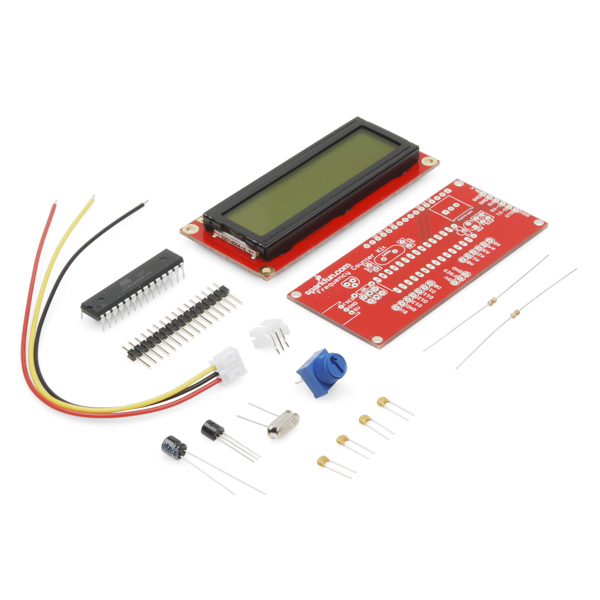
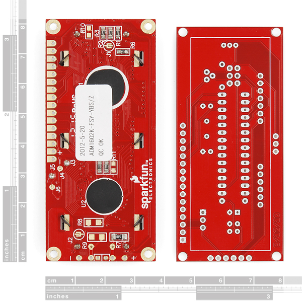
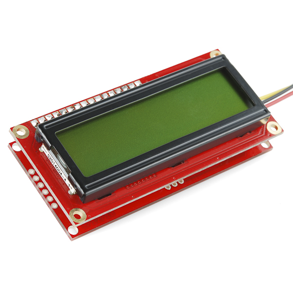
This kit is a re-hash of Nuxie's FunCount frequency counting kit. It includes everything you need to build a frequency counter capable of measuring frequencies from 1Hz to over 6MHz. The measured frequency is displayed on a 16x2 black on green LCD.
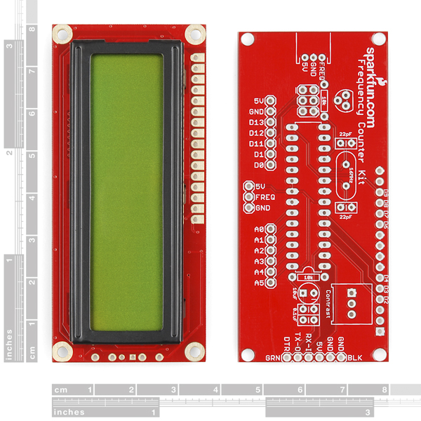
Our new design is based on the popular ATmega328. The ATmega comes pre-programmed with both the frequency counting firmware, and a serial bootloader, so you can program it as you would an Arduino. If you want to program it via Arduino, you'll need a FTDI Basic Breakout. Unused pins of the ATmega328 are broken out for all your custom firmware desires.
The ATmega328 runs at 16MHz, and should be able to reliably count frequencies up to around 6.4MHz (assuming a 50% duty cycle). Voltage supplied to the kit should be 5VDC. The voltage input on the frequency pin should not exceed the supplied voltage, and should not go below 0V.
The kit includes a 3-pin JST male connector, so you can use this wire to deliver +5V, ground and the frequency signal to the Counter. You'll also be able to piggy-back the counter onto our Function Generator Kit (see below).
Replaces:KIT-10014
SparkFun Frequency Counter Kit Product Help and Resources
1 of 1 found this helpful:
Assembly directions
Solder in the two resistors first. They go in the spots on the board labeled 10K. The next parts to add are the capacitors. There are three different kinds in the kit. Start with the 0.1uF caps labeled “104” These both go to the right of the IC. Next place the two 22pF caps in the positions above the IC. Lastly, place the 10uF cap to the right of the IC. This part is polarized and needs to go on the board with the white stripe facing the top of the board.
Now we need to add the crystal. It’s the little metal can. Place the crystal between the two 22pF caps. Next part is the IC. Solder the IC in the center of the board. This part is polarized and needs to be put in with the notch facing the right hand side of the board.
The next part to add is the white socket. It goes on the left hand side of the board with the open end facing the edge.
Solder in the transistor. It’s the black three terminal component that is flat on one side and round on the other. Follow the markings on the board to tell which way it goes in.
Now add the blue contrast potentiometer. Use the marking on the board to see which way it goes in.
Next, solder the header pins into the board so that the short end of the pins are soldered on the top side of the board and the longer ends stick down out of the bottom.
Last step! The LCD display gets connected to the long end of the header pins. In this step you need to space the boards so that the metal tabs on the back of the LCD do not make contact with anything on the back of the controller board. You can do this by eye or use something as a spacer to create a gap. I would suggest only soldering one end pin to the LCD module first, then lining everything up even and then soldering the the other end pin. If everything is nice and straight, solder the remaining pins.
If you ever decide to write your own custom code for this product, you can upload it with a FTDI Basic Breakout and the Arduino IDE. Just set your board type in Arduino to "Arduino Pro or Pro Min, ATmega328 (5V, 16MHz)"
Core Skill: Soldering
This skill defines how difficult the soldering is on a particular product. It might be a couple simple solder joints, or require special reflow tools.
Skill Level: Rookie - The number of pins increases, and you will have to determine polarity of components and some of the components might be a bit trickier or close together. You might need solder wick or flux.
See all skill levels
Core Skill: Electrical Prototyping
If it requires power, you need to know how much, what all the pins do, and how to hook it up. You may need to reference datasheets, schematics, and know the ins and outs of electronics.
Skill Level: Rookie - You may be required to know a bit more about the component, such as orientation, or how to hook it up, in addition to power requirements. You will need to understand polarized components.
See all skill levels
Comments
Looking for answers to technical questions?
We welcome your comments and suggestions below. However, if you are looking for solutions to technical questions please see our Technical Assistance page.
Customer Reviews
4 out of 5
Based on 2 ratings:
Easy
Easy to assemble. Works as advertised. Excellent customer service when I needed it.
Okay, but...
I wished the kit had a sip receiving header to mate with the sip pin header used to connect the two boards. Would make it easier to take apart to replace a failed component. For that reason, I am considering returning it and requested an RMA. After all that, I probably won't, but for the sake of a 25 cent part (it would cost much more in single pc purchase) this would get 5 stars. Very nicely packaged.
Is the LCD that comes with this kit supposed to have a working backlight? I just received one and there appears to be no backlight.
Update: I tried cupping my hands over the LCD and there is actually a very faint glow, which I suppose is the "backlight". Not as bright as what I'm used to, but I guess it will work.
Hi everyone,
I am trying to measures a frequency to the second decimal point. ex using my fluke 115 it measure 978.7 hz, Does this device will be able to get a 987.7X Hz reading? Thanks
Sergio
Hello everyone,
I need to detect a specific frequency (770 Hz) from the ambient sound. Can I use this board with a sound sensor (like this; https://www.sparkfun.com/products/12642) and detect the desired frequency from the sound. Thanks for your help.
Regards,
Nice project. Easy to build. If you need instructions, maybe you should consider a different hobby. I bought this to use as an embedded counter for an SN76477 sound generator. It works very well in the audio range. I tested it up to 4MHz using a calibrated function generator and it tracked just fine when the input was properly terminated. I saw an error of less than a quarter percent over the range I tested it. Cleaning the board is a must. To build it, just look at the values of the parts in the kit and look at the board. It is very clear how to put it together. Lack of socket and hardware is likely what put this project under 30 bucks and I am fine with that. I have sip strip and hardware at my prototyping bench and was more than willing to use it. Don't be discouraged by the genius that is tossing this one into their scrap bin. That person should give up on electronics and get their old job back. No shame in carrying a bucket. Even Kings have to pee. And that should be plenty challenging for a person of your particular skill set. This is a great little counter for embedded projects and it is easy to assemble. If it had been much more than this price I might not have bought it simply because I was looking for cheap and easy. Thank you Sparkfun. I appreciate your work in bringing us useful tools like this.
rsp: This is a nice arduino style concept demonstration kit, but not really much of a frequency counter.
For a more realistic (while still simple) frequency counter reference design, try this:
http://electronics-diy.com/50MHz_Frequency_Meter_Counter.php
Ummm yea, I ordered that kit 9 months ago. Out of the box you had to use jumper wires because of a mistake with the PCB. I wasn't surprised when pads started lifting during soldering. I emailed and complained. I was told I must have soldered it incorrectly - I work in a PCB fabrication and assembly shop. Made me pay for a replacement PCB. When I discovered the PIC included was lacking a program, I didn't even bother to complain. Just chalked it up to getting ripped off.
Jeez - I feel like Ralphie with his Little Orphan Annie decoder ring when he discovered it was just an ad to drink Ovaltine. Come on, Sparkfun how hard would it be to include a socket for the chip and one sheet of paper with at least a pictorial of the completed product? I don't think I'm even going to bother building this - it's going right into my junk parts bin. As Ralphie said, "Sonovab*tch!"
Wow! (not the good kind of wow, either). I have to echo the comments from mcolan. It was very surprising that there were no instructions (except for Nuxie's earlier and different configuration), no socket for the chip and LCD? No standoffs for the LCD and PCB? Well, an order to Digi-Key can fix that, but still as mentioned for a small incremental extra cost some needed additions should have been provided.
Is this the same as the serial lcd kit with different firmware?
Yeah, firmware is most of the difference between the two. The layouts vary a bit, namely the 3-pin JST connectors have different pins broken out (frequency in vs. serial in). The schematics, though, are really similar. The Serial LCD kit firmware would probably work on this kit without needing any modifications.
just a though how much different is this board from your serial enabled lcd that uses a arduino.?
A couple of very inexpensive additions would transform this from a flimsy product to quaity: 1. A socket for the chip. Really? You want your average hobbyist to be soldering a $6 chip in directly, risking damage, when you could supply a socket for 20 cents or less? 2. Spacers, screws, nuts to attach the boards at the corners 3. Perhaps a low-profile socket for the display to allow it to be changed 4. Pins to allow the FTDI to be used These would cost maybe a dollar more on the cost. I'd pay it to have a more complete kit.
The board ought to be reconfigured to have the two JST connectors have the same pinouts. That's kind of a sloppy error.
Some simple instructions - at least a photo of what it is supposed to look like when finished, and some hints on using it - would be useful. It's kind of confusing that you supply a second JST when it's not obviously needed, yet you don't supply more essential parts.
No assembly instructions?
Hmm... Could I hook a mic up to the input and use this as a tuner?
Not a bad little kit, at least if you get bored with it you have a half-decent Arduino dev board. See my review at: http://wp.me/pQmjR-1id
Careful! This device has two identical JST connectors, but the pinouts (+5V, GND, Freq In) are different on each! Double-check before you plug anything in.
so, you have a frequency counter and a function generator.
all you need now is an LC meter.
put everything together and you have a nice tool for frequency, inductance and capacitance measurements...
im sure that with a switch and some simple programing you could through in there a basic Volt meter.
throw it all ina shiny box...
I would buy that.
I wish SFE would make this stuff too, because they'd most likely sell it for the best price. But in the meantime try this for a siimple LC meter kit; it comes complete with case:
http://electronics-diy.com/store.php?sel=kits&sub=electronic_kits
We can check into it.
This is a nice arduino style concept demonstration kit, but not really much of a frequency counter.
For a more realistic (while still simple) frequency counter reference design, try this:
http://electronics-diy.com/50MHz_Frequency_Meter_Counter.php