- Home
- Product Categories
- Kits
- Electronic Dice Kit

Electronic Dice Kit
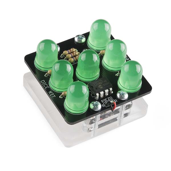
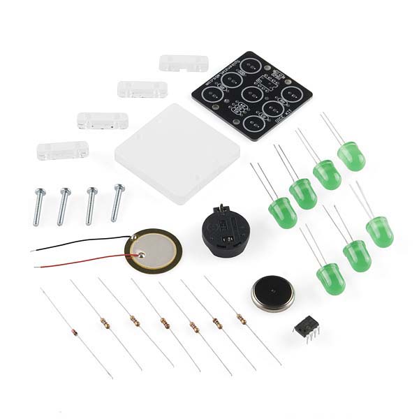
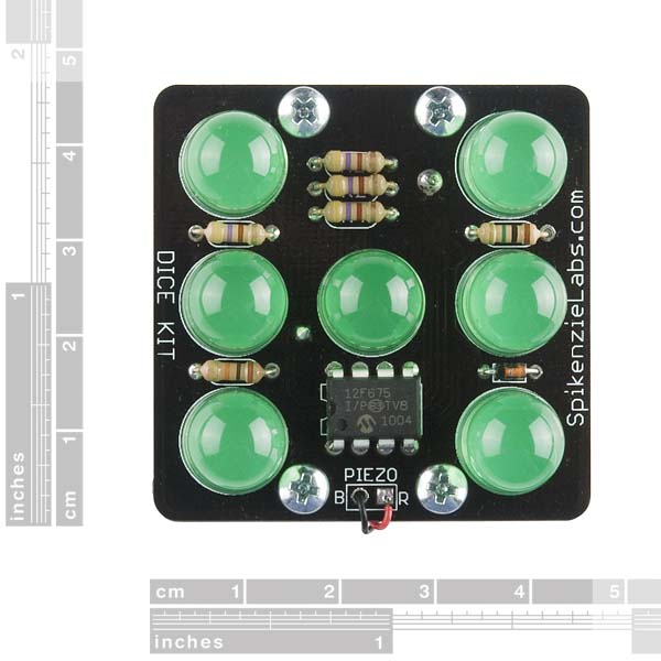
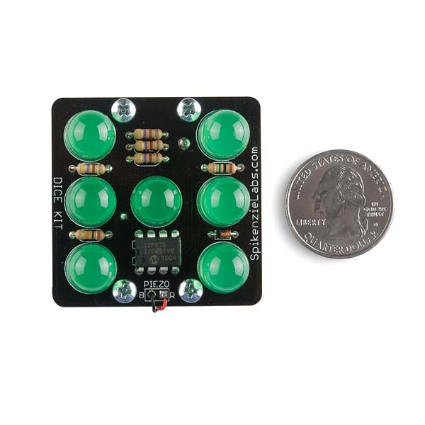
The Dice Kit is a beginner's soldering kit that comes with everything you need to make your own electronic die. When you tap it on the table, it displays a number from 1 to 6 by lighting up the appropriate number of LEDs in the same layout as found on traditional non-electric dice.
The kit uses a piezo element for detecting the tap on the table and uses a pre-programmed microcontroller. It also includes a laser cut acrylic base and battery. There's no programming required and a beginner can get the kit together in about an hour or so. You will need a soldering iron and basic tools. Also, a dab of glue or double-sided tape is recommended as well.
Note: Due to the requirements of shipping the battery in this kit, orders may take longer to process and therefore do not qualify for same-day shipping. Additionally, these batteries can not be shipped via Ground or Economy methods to Alaska or Hawaii. Sorry for any inconvenience this may cause.
- Auto power saving sleep mode after ~15 seconds of inactivity.
- Laser cut 1/4" acrylic base
- Includes CR2032 battery
- Stand alone kit
- No computer needed
- No Arduino needed
- Easy to build
Electronic Dice Kit Product Help and Resources
Core Skill: Soldering
This skill defines how difficult the soldering is on a particular product. It might be a couple simple solder joints, or require special reflow tools.
Skill Level: Rookie - The number of pins increases, and you will have to determine polarity of components and some of the components might be a bit trickier or close together. You might need solder wick or flux.
See all skill levels
Core Skill: DIY
Whether it's for assembling a kit, hacking an enclosure, or creating your own parts; the DIY skill is all about knowing how to use tools and the techniques associated with them.
Skill Level: Noob - Basic assembly is required. You may need to provide your own basic tools like a screwdriver, hammer or scissors. Power tools or custom parts are not required. Instructions will be included and easy to follow. Sewing may be required, but only with included patterns.
See all skill levels
Core Skill: Electrical Prototyping
If it requires power, you need to know how much, what all the pins do, and how to hook it up. You may need to reference datasheets, schematics, and know the ins and outs of electronics.
Skill Level: Rookie - You may be required to know a bit more about the component, such as orientation, or how to hook it up, in addition to power requirements. You will need to understand polarized components.
See all skill levels
Comments
Looking for answers to technical questions?
We welcome your comments and suggestions below. However, if you are looking for solutions to technical questions please see our Technical Assistance page.
Customer Reviews
4 out of 5
Based on 5 ratings:
I really like it
Easy assembly. Nice base and supports. I prefer the acrylic over other dice kits that use PCB for top and bottom with metal supports. Bought two and I need to buy two more once they come back in stock.
a very short term toy...! but great service and eventually, nice toy
Easy to assemble. It worked well... for 5 minutes, then died forever.
Edit: Sparkfun sent me a new piece, which I assembled, and it has been working fine since then. My kids like it
Very good for first timers
The instructional video is a little long winded and some more close up shots would help us understand the details but aside from that the whole thing goes together fairly well for our beginners and works even if the soldering isn't perfect
Didn't work correctly :/
I got everything assembled per the clearly worded directions. This was a fun kit to build.
Unfortunately anytime I tap to "roll" the die, if the LED next to the words "DICE KIT" lights up it immediately "rolls" again with no further input. The LEDs all flash until it settles on a one (only the center LED lit), or some other pattern without the one LED near "DICE KIT" lit up. This includes non-standard dice patterns, like two out of three lit on one long row and one out of three on the other.
Despite the instructions saying that the patterns are determined by the controller, I tried replacing the LED which would not stay lit. With a new LED the same behavior persisted.
You may have a bad board, please fill out the form on this page and we can help. :-)
SO MUCH FUN
This dice kit was simple to build. The satisfaction that you get when you are done building it and it lights up, is awesome! 10/10 would buy again
Not to be overly particular but this should be electronic die kit because there's only one.
From the build instructions: The name Dice kit sounds a great deal better than ‘Die Kit’, so we bent english grammar rules just a little in the name of making a marketable product.
I'm trying to refresh my electronics skills. I remember the equation to calculate an LED series resistor as (Vs - Vled)/Iled. How was the LED voltage and current calculated to come up with a 470 ohm resistor?
Without knowing the exact part number used for the LED's, it's hard to say. (SparkFun does not manufacture this kit.) My guess is they are using a larger than needed resistor to keep the total current down in the PIC and/or to preserve battery life. The LED's are bright enough even at this low current.
Kit video by me :) --------------- Electronic Dice Kit ---------------
I just finished building 16 of these with an after school group of 12 year olds. They all did a great job with their first soldering project, but we had trouble with one kit and I hope someone can help me troubleshoot.
The problematic kit works properly except that the LED in the lower right corner lights less brightly than the rest. I checked the solder joints and they are all nice, full and bright. I guess the only thing to do is to swap out that LED for another one.
Judging from the schematics, that does seem like the only possibility - unless the other LED it is paired with actually burns brighter than the rest (and the other one subsequently less bright) in which case that would be the one to replace.
Thanks. I wonder, is there any possible way that the "bad" LED could glow at all if it was installed backward? With these large LEDs there is no visual way to tell anode from cathode once the leads are clipped, so I was thinking that perhaps if the LED was reversed, it might be glowing slightly when it is in the "off" state.
I've ordered a handful of spare green 10 mm LEDs. But I won't get them until after school is out for the summer.
I hate to send the kid home with a malfunctioning project. I'm hesitating to just pull the LED and flip it because I don't want to do too much soldering and resoldering on the board. But if it is likely that reversed polarity would result in the behavior I'm seeing, it would be worth it to try.
Not typically, no. While there are LEDs that can emit light no matter which way you have them around, they tend to be bi-color type LEDs for status indication (so amber/green or red/green, for example). The only other common way that an LED would emit light when it's the wrong way around is if you put a much too high current on them.. but that would be a brief flash and then it's gone for good :)
If you'd rather not wait and don't mind a bit of soldering - the kid in question might find the process interesting anyway - there's one thing you can try; swap it out for the one in the middle.
If the bottom right remains darker, I am mistaken - although I wouldn't immediately know what to pinpoint as the culprit (incorrect PIC timing seems unlikely, especially since your other 15 builds don't exhibit this problem) - and you're basically back to the current situation.
If the bottom right is now the proper intensity, but the middle appears darker, then the LED is indeed at fault.. but being in the middle it won't look quite as out of place.
In addition, the middle LED is the only LED that isn't paired up, which means that if you have some resistors laying around, you could try making it brighter by lowering the resistance used for that LED, R4. According to the build video, that's the one closest to the middle LED in the group or 3 resistors. If you'd like to go down this path, what you'd want to do is find a high value resistor, let's say a 4.7KOhm (yellow/purple/red), and just press its leads in parallel to D4 - this will decrease the resistance (formula for 2 resistors Ra and Rb: (Ra*Rb)/(Ra+Rb)). That should brighten the LED a bit. If it's not bright enough yet, find a somewhat smaller one and try again. Keep doing that until the brightness appears to be right, but I wouldn't go below a 470 ohm (yellow/purple/brown, same as the ones that come with the kit) resistor in parallel, as that basically halves the resistance and doubles the current to the LED. If you have the right brightness, you could solder this extra resistor into place, though I will readily admit that's tricky given the confined space, and the bottom of the board being unavailable due to the battery holder. Speaking of which, when soldering, always remove that battery first - wouldn't want to accidentally get a short and fry PIC chip :)
Good luck!
Thanks again. I wrote in a hurry and I wasn't clear in expressing my conjecture.
What I meant was: Is it possible that when the LED in question is supposed to be "OFF" (That is, when the PIC switches it off) might there be a reverse current induced in the circuit that causes a reversed LED to glow slightly.
My hesitation about removing the LED and switching it around is not that I am afraid of soldering, it is that my twelve-year-olds already got the boards pretty hot in learning how to solder and I am worried that too much more mucking around may compromise the PCB traces.
Cheers
Yeah, I understand your concern wrt the PCB traces :) I suppose in theory there might be, but the other thing is that when this is the case, it should actually light up brighter when its paired LED is lit (or both would be dim).
If you look at the schematic, the LEDs are basically connected so that each LED in the pairs of LEDs can be driven individually by either setting the left side high and the right side low, or the left side low and the right side high. So if both LEDs are installed the same way around, one of those conditions would light both LEDs up, and the other would have both be dark, and the faces of the die would not look correct :) This pairing is the reason why you can't really adjust the resistor for just the bottom-right LED, it would also affect the current through another LED.
Thanks again. So here is the final follow-up. The kid brought her project back to school on Tuesday and I remembered a tip learned long ago. "Always check the power supply first". In pulling the battery, I managed to make the dice blink a couple of times. I found a cold solder joint for the battery holder; the hard to reach pin adjacent to the PIC. I heated up my iron and gave that joint and every other one a touch of heat and an extra dab of solder. Success. Happy kid,
Also, I learned that while this dice kit does switch to an extremely low current state after 15 seconds of non use, and should run for years on the supplied battery, it is quite possible to wear the battery down much faster. Just carry it around in your back pack for a couple of weeks. I think I managed to keep my sample in the awakened state continuously for about 6 weeks before it died.
can i replace the pezio with a push button?
Thanks.
no because it has to be different every time so the results are random
Is it possible to substitute in the 950nm LEDs? It is for a NIR camera experiment.
You can substitute any LED that has a lead spacing of 0.1" and a forward voltage well below 3V. Ideally they should also be a high efficiency type because of the low drive current. So the COM-09349 950nm IR LED should work fine.
Because the LEDs are strobed, you can't use "intelligent" LEDs (LEDs that shift colors or flicker automatically). Also, depending on how fast your NIR camera is, it the strobe effect might be a problem for your experiment.
Is the output an evenly random number, or is it weighted, or...? Just curious how useful a pair of these could be for gaming instead of dice.
This dice kit is programmed to [attempt to] produce absolutely random numbers; that is, each roll is completely independent of any previous rolls. As a result [over a very large number of rolls] the number of times each value (1,2,3,4,5,6) occurs will be statistically equal and the correlation between all sequences of throws will be statistically equal to zero, where "statistically equal" means that any difference is within a credible interval.
For use in gaming these electronic dice should be better than mechanical dice because they can remove the possibility of the throwing skill of the person from affecting the result. But either kind of dice could be "weighted" (a.k.a. "loaded dice") in order to cheat, and it would probably be easier to detect this by examination when using mechanical dice.
I ran my double-dice mod through a 10,000 roll test and got satisfactory distribution and correlation results. I suppose a robot could be built to tap the original dice and tabulate the results, but that would probably lead to "Arduino Needed" and "Computer Needed".
It uses the analog reading from the piezo sensor to generate a number. So theoretically if you hit it with the same intensity you could roll the same number over and over, but I haven't been able to.
I'm glad to see that people are having fun with the Dice Kit
If you want to see how it was done and maybe learn a bit of Microchip assembly programming. Here is the ASM file. (Not for commercial use.)
http://tinyurl.com/28lazek
"No Arduino needed"? Ok, what do you want to bet somebody goes ahead and adds one anyway?
This would be great kit for learning about random number generation and how to write software for a very low power device, not just how to solder. Except it looks like they haven't made the source code available. So here's some code that I hacked together to get you started: http://www.fearlessnight.com/spikenzielabs-dice-kit/index.html There is also information there on how you might modify your kit's hardware to improve it's performance too.
BTW, the completed dice kit dimensions are: 1.75" x 1.75" x 1.3"
And there's a video of a guy building this kit at: http://www.youtube.com/watch?v=jAuKhCZ8nIQ (or search youtube for "spikenzielabs dice kit")
Enjoy!
Hey SFE folks, is there any way you could add a photo of the finished unit with the PCB separated from the acrylic base so we can see how the piezo sits relative to the battery? I think you can separate (unscrew) the pieces without disconnecting any wires, right?
You are correct. See the "Assembly Guide" link above; it contains the picture that you are looking for.
Is this possible to hack to program it?