- Home
- Product Categories
- Voltage
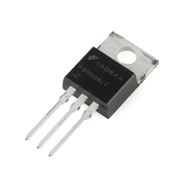
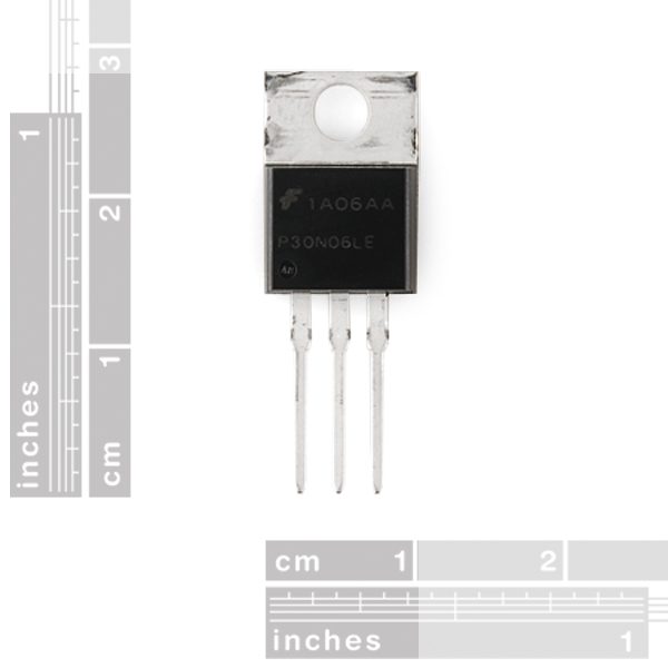
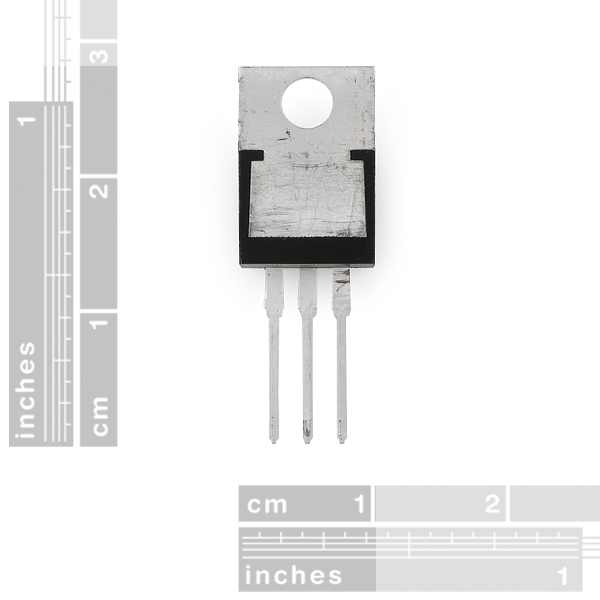
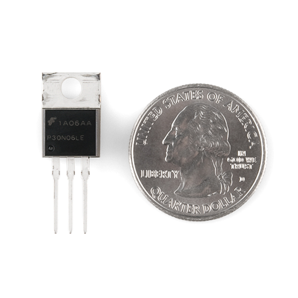
- N-Channel MOSFET 60V 30A

N-Channel MOSFET 60V 30A
If you've ever wondered how to control the headlight of a car from a microcontroller, a MOSFET is what you need. This is a very common MOSFET with very low on-resistance and a control voltage (aka gate voltage) that is compatible with any 3-5V microcontroller or mechanical switch. This allows you to control high-power devices with very low-power control mechanisms.
**Note: **We stock two different models of this component, the two are nearly identical and can be used interchangeably. We've provided links to both datasheets below. We are currently shipping the FQP30N06L.
N-Channel MOSFET 60V 30A Product Help and Resources
Heating Pad Hand Warmer Blanket
January 21, 2013
DIY Project Idea: Create a custom hand warmer blanket using heating pads.
LED Light Bar Hookup
September 24, 2013
A quick overview of SparkFun's LED light bars, and some examples to show how to hook them up.
Hazardous Gas Monitor
June 17, 2016
Build a portable gas monitor to check for dangerous levels of hazardous gases.
Variable Load Hookup Guide - Revised
May 25, 2018
This tutorial will show you how to assemble and use SparkFun's Variable Load board. It can be used to test stability of the power supply under various loads, battery lifetime, safety cutoffs, and other design elements of power supplies under test.
Interactive 3D Printed LED Diamond Prop
April 19, 2018
In this tutorial, we will learn about how to create an interactive theatrical prop for a performance by 3D printing a translucent diamond prop using a non-addressable RGB LED strip and AT42QT1011 capacitive touch sensing.
Motion Controlled Wearable LED Dance Harness
January 30, 2019
Control LEDs based on your movement using an accelerometer! Make your LEDs breathe by fading in and out when laying on the floor, turn off the LEDs when moving to your side, or make the LEDs blink in a headstand!
Magnetic Levitation
November 20, 2019
This tutorial will show you how to build a magnetic levitation circuit using common parts.
Non-Addressable RGB LED Strip Hookup Guide
February 19, 2020
Add color to your projects with non-addressable LED strips! These are perfect if you want to control and power the entire strip with one color for your props, car, fish tank, room, wall, or perhaps under cabinet lighting in your home.
2 of 3 found this helpful:
Trouble switching at high frequencies
If you're having problems at certain high speed switching using this MOSFET, try using a gate current limiting resistance of 100 ohms. This will decrease the time constant enough to keep up with the faster switching frequencies since the gate pin is basically a capacitor with a time constant “tau = r*c”.
Core Skill: Soldering
This skill defines how difficult the soldering is on a particular product. It might be a couple simple solder joints, or require special reflow tools.
Skill Level: Noob - Some basic soldering is required, but it is limited to a just a few pins, basic through-hole soldering, and couple (if any) polarized components. A basic soldering iron is all you should need.
See all skill levels
Core Skill: Electrical Prototyping
If it requires power, you need to know how much, what all the pins do, and how to hook it up. You may need to reference datasheets, schematics, and know the ins and outs of electronics.
Skill Level: Competent - You will be required to reference a datasheet or schematic to know how to use a component. Your knowledge of a datasheet will only require basic features like power requirements, pinouts, or communications type. Also, you may need a power supply that?s greater than 12V or more than 1A worth of current.
See all skill levels
Comments
Looking for answers to technical questions?
We welcome your comments and suggestions below. However, if you are looking for solutions to technical questions please see our Technical Assistance page.
Customer Reviews
4.8 out of 5
Based on 4 ratings:
4 of 4 found this helpful:
great little thangs!
I first came across this little thing via the MOSFET power controller listed here: https://www.sparkfun.com/products/10256
and found loads of fun and practical uses for the device.
taking the basic practical application of the device I resurrected a vintage traffic signal light by first gutting it,and then modifying a traditional 555 based LED traffic light simulator, replacing the LEDs with these MOSFET's and using them to drive a bank of 12v DC lamps to make the old traffic light work through its functions as an accent lamp. the chip are a great value at the price point, and I highly recommend them
1 of 1 found this helpful:
Very useful
This works great, I've used it in various projects, to control bright LED lights and heating pads from a microcontroller, for example.
1 of 2 found this helpful:
Awesome little device!
I just can't get enough of them!
Work just fine
And cheaper than other sources until I need 100.
Any tips on insulating the drain tab to prevent accidentally shorting drain-source and bypassing the gate control entirely? Expected load is ~7A at 12VDC; infrequent switching (on the order of seconds); open (no load) vast majority of the time. So I doubt I need a heatsink. Will this burn up if I just cover it in heatshrink or something like that? If so, what kind of thermally conductive, electrically insulating TO-220 wrapper can I get in small quantity? Thanks!
I'm thinking of using this along with an Arduino to create a Bluetooth controlled power distribution box. Essentially 6 or so fuse protected circuits that are each toggled on (individually) by activating this MOSFET. This would be a 12v box (and used in a vehicle). Max amps per circuit would be < 20amps. Would this work or would relays be better. I would like to use PWM to set a duty cycle on the circuits so that's why i liked the MOSFET idea. I didn't think a relay could support fast pulsing. And what sort of flyback diode would be good? I'm very new to HW development, I've been writing software for 15 years but that doesn't help with the electrical stuff. Thanks a lot for any advice.
This is versatile and works great. I'd like to find an SMD part that is as close to this as possible, any recommendations?
Note that when using a N-Channel MOSFETs as a a high-side power switch (i.e., drain tied to V+ and the source feeding a motor), the FET will not turn completely 'on' by simply bringing the gate voltage up to V+. You will need to bring the gate voltage ABOVE the rail voltage to get the FET to turn completely on.
The easiest way to do this without requiring a second higher rail is to use a "charge-pump" driver between the microcontroller and the FET's gate. The LTC1155 is one such device. It is particularly useful, because it can drive two N-Channel FETs as power switches for controlling a pair of robot motors, or for switching power to other high drain circuits.
The LTC1155 is such a useful circuit, it might be nice if SparkFun carried those as well to complement these N-Channel FETs.
P.
Thanks for the comment...... but it does not pertain to these mosfets ;-)
These mosfets are logic level mosfets and they have something similar to a charge pump built into them already, these will turn fully on when applying a 5v signal from a microcontroller.
You really made me think twice about buying these too, but I just tested these. I switched a 7.3v source across a 30ohm resistor and measured 243ma like your supposed too. I used 5v from my microcontroller to the gate to do the switching. I tried this setup the other day with a normal mosfet and it didn't come close to turning fully on. Ohh well, now we all know the importance of a charge pump :-)
Wow, you're right. The datasheets sure don't make that obvious.
It's kind of misleading that they use the diagram for a regular FET for this device. Pretty much any other device with this symbol will not switch completely on if the gate voltage is less than the rail. It's only because these parts have the words "Logic Level" in their titles that they don't need a charge pump driving the gates.
Bottom line: If these devices are your first foray into power FETs, be aware that most other power FETs aren't this easy to hook up to an Arduino!
They make that quite obvious, it's a regulare FET, just the Gate Threshold Voltage is very low (2.5v max) They should probably be classified ultra logic level, as i belive logic level has a Vgs(th) of 4v.
"Logic Level" just means a spec for R_DS at V_GS = 5, nothing else. No charge pumps here.
A friend once brought me a board showing the aftermath of trying to drive a high-side configuration with 5V... there was definitely no more magic smoke left in those FETs.
Has this changed? I just got one of the FQP30N06L models and it seems to work much like the regular MOSFETs I have had. I hook +5V to drain, and if I put +5V on the gate, I only get about +4V out of the source pin. This is no different from a "regular" N-Channel MOSFET. Just wondering if the RFP30N06LE model might be different.
There's no charge pump in these, the Vgs(th) is just very low. To see more accurately "how on" the fets are, check the graph in the datasheet, showing Vgs and current flow
The easiest way to use this is to tie source to ground and drain to motor and drive gate with 10 volts from ground. kinda like this link
N Channel Mosfet
Hello Peter, I've been working on understanding your comment about the need for a charge pump to drive the voltage at the gate above the rail voltage to get the FET to completely turn on and I'm beginning to understand (i'm new to all this).
How would I use the LTC1155 to bring the gate voltage above 12V with a 5V signal from the microcontroller?
That would be useful too. Another option is the non-inverting configuration of this:
IXDN604
That's a nice circuit too. But there's a lot more than just a FET in there.
My point was simply that pulling the gate of one of these N-Channel FETs offered by Sparkfun to V+ isn't enough to get it to act like a switch. You need a charge-pump chip to drive the gate.
P.
1 word: Booya
You need a transistor to drive the gate of the MOSFET else you won't be able to turn the MOSFET off completely.
What kind of trace width would be needed for 25-30amp?
30A would require quite a wide (or thick) PCB trace. There's a nice calculator for this at http://www.4pcb.com/index.php?load=content&page_id=95.
Note that putting 30A thorough this MOSFET is only possible under certain conditions. The operating voltage, heat sinking, and gate drive voltage all have to be just right.
Well, if you are going to run 30 amps at 60 volts, You better be switching that thing HARD! I t only has power dissipation of 96W, which, admittedly, isn't bad, but give that gate loads of current. Also keep in mind the turn-on and turn-off delays. If you need to pump that much power I recommend using an irfp250 or irfp260. It is still feasible though. Good Luck!
Cooling your board helps.
This is awesome! I can't wait for the P-channel FET. It's going to be twice as awesome!
Finally!
Well, These mosfets looked like a great deal when I first saw them. A dollar for a 30 amp mosfet? Wow, that was a great deal. I ordered 8 of them.... I built a light duty inverter with them, pushing no more than 1 amp at 5 volts. All the mosfets started to leak current, well 4 of them I used for the inverter. I even had them heat sinked. I had 4 left, and I used them for some bread board prototyping.... Well 2 of them broke int hat case, they would not close the damn circuit! They leaked 10% of the current I was running through them. I had 2 left, and I was building a motor controller.... They are rated for 30 amps right? Well ran 20 amps through one, and after a few cycles... It started to leak... 40% of the current I was running through it. So when the voltage at the gate was zero, 6 amps were running through the mosfet. it would not turn off. I have no idea why they did this.
I hooked them up properly, heat skined them.... What the hell is wrong with these mosfets? They are really setting my projects back. Anyone got any advice?
please fix bildr tutorial
Bildr is an external site that we have no control over. If you are having problems with their tutorial please post a comment on their tutorial letting them know what is wrong and they should get back to you.
I love these- been using them w/ Arduino to drive multiple 12V LED strips.
Now, though, I'm trying to make a basic electromagnet (use an Arduino to slowly turn it on & off using a changing duty cycle) and I'm burning these things, my Arduino, and my board up I think for 2 reasons
1) I'd LIKE to run 12-24V at ~10Amps and the dissipation on these is 96W; I tried running multiple of these in parallel but no luck eventhough they're supposed to be self-balancing as they get hotter. 2) This MOSFET gets stuck in the open phase i think; if the duty cycle is too high, the 0 or 5V Arduino logic can't seem to turn off the MOSFET when the 12V & 8A is going through. It gets stuck on an boils everything. Does that sound right?
So I think things get complicated when you want way more power. Can someone help me with some suggestions? I thought maybe a relay, but I definitely need to run this at all ranges of current between full load and just a little bit so i think a relay won't be able to switch fast enough to give enough resolution on the duty cycle, no?
I think I need a heavier duty transistor to solve this, but I've no idea which one (someone here mentioned IRFP260?) and with these higher-power ones, how to drive them w/ Arduino logic. Can you use the 5V Arduino logic to turn on this N-MOSFET and let a 12V VIN pass through to then trigger the bigger transistor?
Thanks!
Can the signal of a RC receiver be used to control this MOSFET? Ei. Connect the gate pin directly to the signal pin on a rc receiver.
It should be noted that this part has a high gate resistance and consequently high rise/fall times. This makes it a very poor choice for any kind of switched power supply.
I bought two of these (FQP30N06L) and I followed the bildr tutorial, initially running them on a switch mode power supply (TOL-12889). Neither worked correctly at first--they barely let any power through or none at all--and now they won't shut off. If I run a simple PWM routine, I can see the light fading a little but it never shuts off. Can this be a result of running them on the switching supply?
I'm completely lost with this and could use some help.
I'm trying to make an h bridge that can be triggered by a 3.3v arguing pro. I am trying to power the motor with a 3.7v lithium battery. Straight from the battery, the motor gets adequate power. Through the mosfet, though, it barely runs at all.
I don't understand mosfets well so can someone clear up why I get a voltage across drain to ground that is about 1.5v lower than whatever the gate voltage is? This is found in an example where the source drain voltage is 4.5 and I tried a gate voltage of both 4.5 and 3.3v with no gate resistor.
Will this mosfet just not work for my purposes or am I doing something wrong?
Power MOSFETs have really low gain. To control 3.7v, you want the gate voltage to be HIGHER THAN 3.7v.
Has anyone tested these with a beagle bone black? They have GPIOs that output 3.3V with only 4-6 mA. I'm afraid that's not enough to get these turned on all the way. Thanks!
That depends entirely on the voltage being controlled. Like any other power MOSFET you need a higher voltage at the gate than the voltage you want to control.
Any simple way to test these guys for failure? I think I managed to fry a couple of mine.
wired up like so: D - neg lead from 12v led strip G - touched to gnd and 12v manually for testing S - Gnd
When I ground the gate the led strip goes full on, and when I apply 12v it gets very dim but still on. Does that seem to indicate failure? If so I'd love to learn my error to avoid the same stupid mistake in the future.
I'd double-check your wiring. Grounding the gate should turn off the LED strip. Raising the voltage above 2.5V should turn the LED strip on. Don't let the gate go above 20V.
The fact that the led strip is doing something in response to gate voltage changes would seem to indicate wiring error rather than a busted device. Usually letting the smoke out leads to solid-on or solid-off behavior in my experience.
I have this and the corresponding breakout board connected to a 12V solenoid (which is connected to a beer line) and a GPIO pin of a Raspberry Pi (powered by the 5V side of the same molex connection powering the solenoid). The Pi outputs 5V for a specific period, then drops to a few mV. The solenoid opens just fine, and the beer flows great (nice head), but it doesn't ever close. It's great for getting drunk, but kind of ruins the project.
I measured voltage across the solenoid terminals, and it goes right to 12VDC, but never drops below 5VDC. I think the pressurized system combined with a relatively high "low" voltage (5VDC) is preventing the valve from closing. Any ideas how to get it closer to 0V when the Pi's pin is low?
Sounds like the pull-down resistor between the gate and ground isn't doing its job. Check that you do not have a cold solder joints on either side. Assuming this is the breakout board that you mentioned, with nothing connected to it, see if you have 10kΩ between the 'C' and '-' terminals on the 'system' side. Also, be sure to have a diode to protect the MOSFET from kick back on the solenoid.
After measuring the resistor and getting something in the 350Ohm range, I tried resoldering, then replaced with a new resistor altogether, and eventually came to the conclusion it's probably the MOSFET. I got the same resistance with both resistors, and my multimeter jumped all over before it finally gave a reading every time I tested. I'm going to try a new MOSFET tomorrow. Thanks for your help l0gik!
Here's the solenoid we purchased: http://www.ebay.com/itm/3-8-Electric-Solenoid-Valve-NSF61-Potable-Water-12VDC-24VDC-VAC-110-120VAC-G28E-/290791658142?pt=LH_DefaultDomain_0&var=&hash=item43b488929e (12VDC, 500mA).
Never mind, I didn't check the power rails on my breadboard, with the adafruit PS i had on there the +&- were swapped......DOPE.
I'm a bit confused, I have bread-boarded this up to control a simple 12v (~12watt)light bulb. here are the connections: FET pin 1, 10k pull down to ground FET pin 2, Ground from light bulb(high current) FET pin 3, Ground
Other terminal from light bulb is connected to a 12v power supply (5 amp) If I understand it correctly, in the above configuration the bulb should stay OFF, as there is no voltage applied to the gate (pin 1). However, the bulb will light. If I apply voltage to the gate pin (I first tried 5v through a 330ohm resistor, then 12v, then no resistor at all) the bulb remains lit. I ordered several of these and so far 2 are never switching off.
Is it possible that these suffered static damage? Or am i trying to use them wrong (I doubt this as I checked the wiring against the FET board SF sells).
Sounds like the right hook-up to me. Double check your "pin 1" etc against the datasheet. I find it easy to mix up the sides of this device. It's also possible there's static damage; MOSFETs are traditionally very sensitive to static. Modern devices aren't nearly as sensitive as in the "old days", though, and I've routinely handled MOSFETs with no special precautions without doing any damange. (And static damage tends to show up as a degradation of, eg, current-handling capacity, rather than a complete "shorted on" failure.)
I am thinking of building a constant current sink to sink about 60A. The idea is to use a comparitor to set the gate voltage on a logic level mosfet that will consume xx V. My question is, given that one of these MOSFETs should only be driven to approx 30% of rated current drain, can I run, say 5 of these in parallel to dissipate the 60A drain ? Any help appreciated.
I'm wondering the same thing.
I just bought 3 of something. are they the rfp30n06le or the fqp30n06l.
Quick question: I tried using this to drive a 0,5A/12V motor in PWM from a arduino, and switched the frequency to 62kHz to avoid audible noise in the motor. It works quite as expected, but I red there could be heat problem at higher frequencies, should it be a worry at 0,5A? (I don't use a mosfet driver, gate is behind a 10k resistor).
I know it's not very pro build but I wanted to test LTC1155 recommended by PeterG in 1st comment.
Arduino nano + LTC1155 + FQP30N06L running at ~7A without heatsink. Default ~1kHz frequency. Mosfet barely warm after 5 minutes.
http://www.youtube.com/watch?v=WnlHkQXQ1c0
Would this be a suitable replacement for a STP16NF06L? For reference, I am trying to do this project with a Arduino Leonardo http://www.ladyada.net/products/rgbledstrip/. Thanks in advance.
will these mosfets be able to handel the amount of power that come from "Spark Gap Igniter" product COM-11218 ?
Anyone know why these are rated the same (30A) as the lower voltage Adafruit mosfet? The RdsON here is 47millOhm, and there it's 16mOhm. So, I figure these guess should manage more. -Are the leads the part that limit the max voltage?
Can someone please elaborate on the max power dissipation of 96W? 50Vx60A = 3,000W?
The ratings are exactly what you would expect. The MOSFET can handle a max of 96W, or 50V, or 60A, not 50V and 60A. So it could do 50V and 1.92 A, or 1.6V and 60A. Anything less than or equal to 96W
I was wondering if I could use this MOSFET to control a 300W scooter motor with my arduino. The voltage through it would be 24V. These conditions seem to be within the range of this MOSFET, but I just wanted to make sure I should attempt this. Any help would be greatly appreciated. Thanks!
If you take a look at the datasheet, the max power dissipation is 96 W. You would need something higher power than this mosfet to control your scooter, I recommend looking at mouser or digikey.
Thank you for your response, I was looking for the appropriate MOSFET, is there any specific one you recommend?
The two FETs are very different at low gate voltages. The RFP30N06LE has a threshold voltage of 2V or less, while the FQP30N06L has a threshold voltage of up to 2.5V. As a result, the former can drive more than double the current at 3.3 V.
Which parts are you currently stocking? I suggest that you remove the latter completely and only stock the former.
Would this be a good idea for something like switching a lightbulb with an Arduino? Would it handle AC fine?
SparkFun carries several products that can switch AC at high current. Take a look at our Solid State Relay Kit, the Beefcake Relay Kit, and the Powerswitch Tail.
Ok! Thanks!
If you want to switch high-voltage, high-current AC, I would look into using a transistor and a relay. There are many relay breakout projects or you could build your own on a breadboard. Most relays are designed to switch 250V AC at 10A. The transistor is used to allow a micro controller to switch a higher current to close the relay (typically requires 200-300mA).
"If you've ever wondered how to control the headlight of a car from a microcontroller, a MOSFET is what you need." Would be very cool to have a sample of this. This is pretty much what I want to do, but there is an overwhelming number of samples/examples/etc/ad nauseum. I'm not an EE, could be considered an uber-novice, trying to figure out some of this stuff.
If I apply a voltage to the gate which is lower than 5V, then will the output vary accordingly? I need a way to control the voltage of a high power load from my Arduino.
Power MOSFETs are only good at handling power because they have such a low resistance that they can carry a lot without warming up much at all. Try to control the same loads linearly and they let out the magic smoke.
At the very least you will need a beefy enough heatsink and fan to suck away the xx watts of heat it will be generating.
I am having a problem getting my circuit right with this, with the breakout kit I can %100 perfectly turn on and turn off a Rebel LED and a laser pointer (flashy light show project). But when I Try to breadboard this with the actual mosfet I get a completely different behaviour. When the output from the pixace pin is off, the laser stays on,and the LED goes dim, when the input is on, the LED goes bright, no visible change in the state of the laser.I tied the pixace out/mosfet in to ground with 10k like the breakout, is the breadboard the difference, or have I botched this?
I have a few of these, and I attempted to control a 12V light with it, I could not get the light to turn on using an Lilypad.(I tested attaching the light directly up to the source which worked, and I have a multi-meter showing me that I have a solid 3V Vgs). I have a limiting resistor and an a pull down resistor in place. I have tried with V+ hooked up to the drain and the Light hooked up to the source to ground, I have also tried with V+ hooked up to the light and the drain hooked up to ground(From PeterG's first comment I didn't expect the second way to work either). Did I misunderstand how this can be used, or am I using it wrong? I thought the whole point was you can use this as a switch for higher power loads that the microchips can't power directly? Sorry for the long post, I am lost... Thanks for your help!
Power MOSFETs have very low gain -- often smaller than one. You need to control them with a higher voltage than the voltage being switched. This is because they're voltage-controlled devices.
Sorry but 60V is the min or the max voltage on the drain? I'm new to electronics. On the datasheet I see it's minimum voltage. So I can use it also for 250V? Or I should use another one?
Thanks!
N
60V is the absolute maximum rating on this, plus if your talking about 250V AC it will run current in incorrect ways, plus burning this chip out in a second.
Can I use this MOSFET to drive a DC 5V fan connected to Arduino Uno?
Yes. You will need a pull down resistor on the gate pin, and possibly a current limiting resistor hooked up in series between the IO pin on the Arduino and the Gate pin on the Mosfet.
Thanks for the advice! I'm totally new to electronics so I've got some more questions. The info I found online for calculating the pull down and current limiting resistor pertains to LEDs only. How would one calculate the values for both for my case?
Also I assume the circuit diagram to be:
Mosfet Gate Pin -> pull down resistor -> current limiting resistor -> Arduino IO
Positive lead of Fan -> Mosfet Source Pin
Mosfet Drain Pin and Fan Negative lead to ground
Have I got this right?
Can this same setup be used to low power parts such as a multiplexers or an ADC? Or will the low current draw somehow mess with how the mosfet works (I'm not familiar with them). I'm just wanting to use the mosfet as a switch for a group of sensors and parts that I can turn off periodically to conserve power.
Thanks for the additional tips. Just want to also check if I need an external 5V power source for the fan or can it be powered entirely from the arduino uno board? Can I just connect the positive lead of the fan to the positive of the breadboard and then connect that to the arduino 5V?
It depends on how much current the fan draws. I suggest you get a 5V Voltage Regulator, and connect the fan independently of the Arduino. Do connect the Arduino's Gnd to the regulator's Gnd though.
Make sure you put a capacitor between the external 5V and Gnd to filter any noise from the fan.
The fan draws 1000mA: http://www.alibaba.com/product-gs/400684756/USB_Computer_Desk_Cooling_Cooler_Fan.html
Do I still need an independent power source?
If so, how does the 5V regulator fit into the circuit diagram above? Is the Mosfet still necessary?
Thanks for all the help!
You're going to need a fairly large power source. I suggest you get an Atx Power supply and use its 5v line. you will still need the mosfet to control the fan.
So that means the final circuit is like so, right?:
Mosfet Gate Pin -> Pull Down Resistor -> Gnd
Arduino IO Pin -> Current Limiting Resistor -> Mosfet Gate Pin
Mosfet Source Pin -> Gnd
Mosfet Drain Pin -> Negative Fan Lead
Positive Fan Lead -> Vout of 5V Regulator
Vin of 5V Regulator -> Positive lead of 5V line of ATX
5V Regulator Gnd -> Arduino Gnd
Negative lead of 5V line of ATX -> Capacitor -> Negative Fan Lead
BTW what value Capacitor should I use?
If you use the Atx power supply, you will not need the 5V regulator. Instead, connect the positive fan lead directly to the power supply's 5V line. The negative side of the capacitor is connected to Gnd and the positive side is connected to 5V. I suggest you use this one. Also, all Gnds should be connected together. I have condensed everything down into this for you:
* Arduino IO Pin -> Current Limiting Resistor -> Mosfet Gate Pin
* Mosfet Gate Pin -> Pull Down Resistor -> Mosfet Source Pin -> Gnd -> Atx Gnd -> Arduino Gnd -> Negative Side Of Capacitor
* Mosfet Drain Pin -> Negative Fan Lead
* Positive Fan Lead -> Atx 5V -> Positive Side Of Capacitor
Is there an eagle file for this?
I use a modified version of the adjustable voltage regulator sparkfun carries. Its the same footprint, you just have to rename the pins.
I used the bigger brother of these mosfets, the FQP47P06 p-channel and the logic-level FQP50N06L n-channel to build a few high-power motor-controllers - using three of each mosfet in parallel for each switch in the H-bridge. They worked well, more info here:
http://www.rediculouslygoodlooking.com/site/triple-8.html
[comment removed]
That depends on the language you speak. In spanish is "el transistor" no "la transistor", so is masculine.
Well, dynamite is la dinamita, and a dress is el vestido. Gender identification in language is not necessarily consistent with actual gender.
???
+1 for spanish student.
How long will this MOSFET stay on after a 5V signal is disconnected?
I would say close to indefinitely. I wired up something like this on my breadboard. Used a 3v source to turn-on the gate (to power an LED) and then disconnected the power to the gate and the LED stayed on. I even disconnected the power and reconnected the power and the LED came on immediately with no signal to the gate. (iow, the gate [capacitor] was still holding its charge.)
To remedy this, I put a 1 MOhm (1,000,000 ohm) resistor between the gate and ground. Despite the high resistance, this still allowed the gate to turn off instantly, yet draw very little current from the signal that switches on the gate. I was able to do PWM control of my LED and everything seemed fine.
I guess if you wanted to make sure it was turning off faster, you could use something like a 10KOhm or 100KOhm resistor at the expense of drawing more current from whatever is providing your signal.
Yes: use a pull-up/pull-down resistor to ensure that the gate is discharged. You should never let the gate of a FET-style device float. That stray capacitance picks up all sorts of things from the environment (RF, stray electric fields) and unpredictable things will happen in a circuit with a floating gate --- including destruction of the device in the worse case (stray electric fields can cause latch up, although this is not common).
Is this why when I use a basic circuit (connected, on and off doesnt matter) My finger can cause it to switch on and off unintentionally??
(I assume you're talking about a 5 volt signal driving the gate, referenced to the source.)
Using i = C * dV/dt, rearrange so dt = C * dV/i, and using the input capacitance, your drive voltage minus the gate threshold voltage and gate leakage current you can get a rough idea.
But if you notice, the gate leakage current can be either positive or negative. Bottom line: don't depend on simply removing the gate drive to turn it off.
Sorry for a nooby question, but at how many hertz could I turn this on and off? I was thinking about building an electromagnet which will be pulsed at maybe 100hz or something. Together with a sensor I will try to make it levitate an iron ball.
100 Hertz is trivial for this part, it has a turn on time of 140 nanoseconds and turn off time of 100 nS, but you need to drive the gate properly. While the gate current is negligible, there's a very large capacitance that needs to charge (look at the gate charge and input and output capacitance in the spec), and when it's between all the way on and all the way off it will dissipate lots of power, so you usually want to make that transition quickly, though with a 100 Hertz rate that's probably not going to too bad. Te transient thermal impedance spec will help you there.
Also, if you're driving an electromagnet, that's a big inductor, and when you switch current there will be large voltage spikes which can easily damage the part, so you need to clamp that.
If you're new to this aspect of electronics, one great resource is the application notes manufacturers publish, they want to help you use (and buy) their parts. For example, if you go to http://www.fairchildsemi.com/apnotes/power_management.html#MOSFETs and download app note AN9010, there's a good introduction to how MOSFETs work.
Hope this helps, and good luck with your project.
A P-channel equivalent would also be very useful.
Yep, it's coming.