- Home
- Product Categories
- Weather
- Humidity sensor - HH10D

Humidity sensor - HH10D
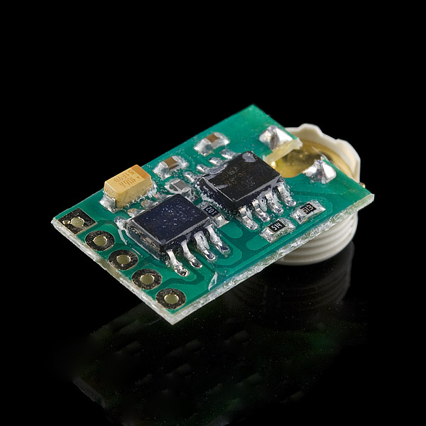
The HH10D relative humidity sensor module is comprised of a capacitive type humidity sensor, a CMOS capacitor to frequency converter and an EEPROM used to hold the calibration factors. Due to the characteristics of capacitor type humidity sensor, the system can respond to humidity change very quickly. Each sensor is calibrated twice at two different accurate humidity chambers and two unique sensor related coefficients are stored onto the EEPROM on the module.
- I2C interface
- 2.7-3.3V Input
- 150uA current consumption
- -10 to 60 degrees C temperature range
- +-3% accuracy
Humidity sensor - HH10D Product Help and Resources
Core Skill: Soldering
This skill defines how difficult the soldering is on a particular product. It might be a couple simple solder joints, or require special reflow tools.
Skill Level: Noob - Some basic soldering is required, but it is limited to a just a few pins, basic through-hole soldering, and couple (if any) polarized components. A basic soldering iron is all you should need.
See all skill levels
Core Skill: Programming
If a board needs code or communicates somehow, you're going to need to know how to program or interface with it. The programming skill is all about communication and code.
Skill Level: Competent - The toolchain for programming is a bit more complex and will examples may not be explicitly provided for you. You will be required to have a fundamental knowledge of programming and be required to provide your own code. You may need to modify existing libraries or code to work with your specific hardware. Sensor and hardware interfaces will be SPI or I2C.
See all skill levels
Core Skill: Electrical Prototyping
If it requires power, you need to know how much, what all the pins do, and how to hook it up. You may need to reference datasheets, schematics, and know the ins and outs of electronics.
Skill Level: Noob - You don't need to reference a datasheet, but you will need to know basic power requirements.
See all skill levels
Comments
Looking for answers to technical questions?
We welcome your comments and suggestions below. However, if you are looking for solutions to technical questions please see our Technical Assistance page.
Customer Reviews
No reviews yet.
Wow, that's ugly.<br />
<br />
...from my experience that should mean it works like a charm, lol.
The Arduino Article link draws a 404 error - in Russian.
ай Carumba!
Guys - the correct link to article is http://tushev.org/electronics/arduino/item/47-interfacing-hh10d-with-arduino
It still does...
Because I'm a stickler for code clarity I put together a library for this module: https://github.com/crackmonkey/arduinolibs/tree/master/HH10D It works in interrupt mode on my Fio v3 (after stealing WInterrupt.cpp from teensyduino) as well as using pulseIn for less accurate readings if you don't have a free external interrupt to use. It can also optionally read the calibration constants from the EEPROM, but if you set the constants manually Wire doesn't get included in your sketch. Semyon Tushev did the real work, I just beat it into a prettier package.
Here you can find a copy from Simon Tushevs article (http://bit.ly/122ZZdK "Interfacing HH10D with Arduino")
Great Product! The board came as a GREEN board, just as shown in the picture!
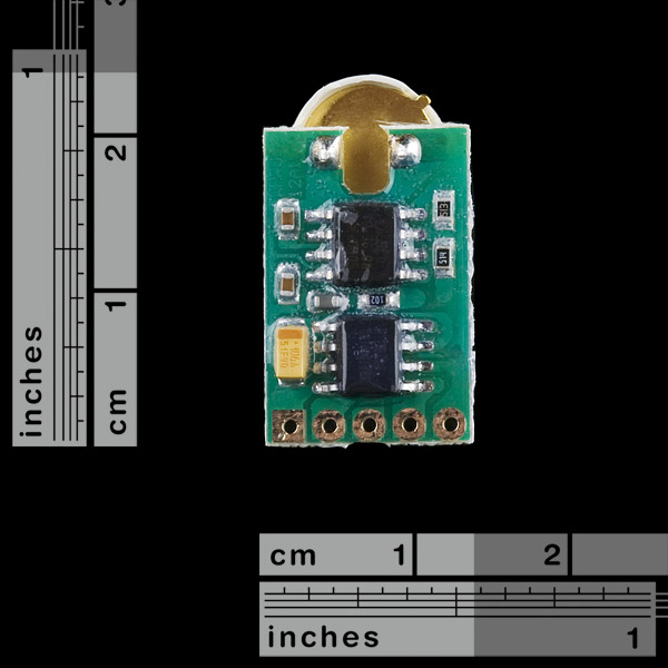
One thing you'll notice about this board is the solder pads are not through-hole plated. This might account for some of the problems people are seeing -- it's going to be rather difficult to get good connections by pinning it down to a breadboard. It wants to have a connector soldered on it first.
However, the solder pads on the one I received were coated, thinly, so I didn't notice it until I started soldering and the conformal started to smoke and turn black. You won't get a good joint unless you remove it first. (Back when I was a kid, they often used parafen.)
Well I connected it to an arduino, and the output is very noisy, it's changing for 1% RH or 2% RH even after averaging 5 readings. is the sensor faulty?
How could this be used with a raspberry pi?
Hello !
I post a comment here because i try this sensor with an Arduino Uno and i can read the Cal data without problem but it is impossible to measure the frequency on Fout pin.
I use a FreqCounter library finding on internet which use timer1 and pin D5 for external trigger. I don't have any oscilloscope but with a simple multimeter i measure 1.7 V on Fout pin and 0V when connected to D5.
Is any adaptation needed ?
Thank you for your help ;)
I spent several hours trying to get mine to work to no avail. I saw someone mention that they got one that had bad cal constants in EEPROM (I'm reading 0s out of the four bytes where the cal constants should be). I ordered another one to see if it has the same problem. I'm also seeing that on about 10 feet of twisted pair (with the other line at +3.3V), the frequency isn't stable -- it drifts by a 1000 Hz in a stable atmosphere. The output impedance of the circuit looks like 1k, so that's confusing -- I'd expect that would be enough drive. When I get a chance to put it on a scope, I want to see what the signal looks like at the micro. As an aside, the BMP-085 I have is stellar.
The first of these sensors lasted about a year and then started to drift. Saturated humidity remained, but lower humidities started to show higher and higher frequencies. I replaced it in mid-September 2012.
Having written the above a week ago, I wanted to follow-up. While the cal data in the device seemed wrong, I was able to figure out cal data on my own. With that, I've had really good luck. The frequency drift went away when I moved the sensor away from my laptop and hooked it up to another PC. I don't have a root cause as to why. Go to weather underground, look for weather station KWIAPPLE11! My sensor is at 100% RH at about 7925 Hz. At 0% RH I'm at 6565 Hz. I got this by comparing my measured RH with data from a nearby weather station. Plot frequency versus RH. Write the equation!
Has anyone here had any luck getting this to work with the Netduino?
Device i2c address is 81, not 1 as specified in datasheet.
(Because M24C02, its EEPROM, has id of 1010 + 001 as first data bank, so 1010001b = 81d)
A few tips on this device:
- you only need I2C once to read 2 values from eeprom; you can make those values constants in code and disconnect i2c
- eeprom values (sens and offset) are stored with MSB first (ex: sens is a 2 byte value, addr 10 is MSB and addr 11 is LSB)
- sens should be appx 300-400, offset appx 7500-7700
- only 3 pins are needed to read values (vdd, gnd, fout), fout outputs pulses representing a frequency 5-10khz, you must count the rising edges to calculate freq
- I could not get accurate readings using a 6" jumper wire, I had to solder a pin to fout and plug in directly at mcu
- here is an example of my eeprom values along with a sample fout reading and the calculation to get RH:
eeprom sens: 405
eeprom offset: 7504 (the value in eeprom is in hz)
sample fout rising edge count in 1 second: 7335 (i.e. 7335 hz)
plugged into the calculation from datasheet:
(7504-7335)*405/4096 = %16.71 relative humidity, which I confirmed with a different sensor
Right now I'm running mine off about 30 meters of cable. I'm using an Arduino. I've noticed that if I power the Arduino off my laptop's USB port (rather than a wall transformer) I have trouble.
I had a lot of RF interference with my jumper wire, until I shielded and grounded the shield. Seems to be working now: the values won't change anymore as I get my hand closer to the wire.
Has anyone actually tried to package this for use outdoors where an RH measurement might be interesting?
nejtek:
How do i switch to other I2C slave if i have more? I'm not seeing any XCLR outputs. Also, what is FOUT for?
This is awesome! I was having a hard time talking my self into the SHT15 because of the price and the HH-4030 is analog. This is the best of both!<br />
From the datasheet, it looks like it's using an M24C02BN6 2 kbit EEPROM, and you have to read out some values to do the calculations and adjustments on your microcontroller.<br />
<br />
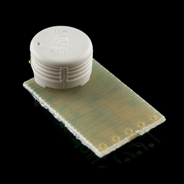
From the picture, it looks like it's been dunked in epoxy. Is that true?<br />
<br />
I'm wondering if I can cut and/or solder through that shiny crud that's covering the PCB to adjust the I2C address. If that doesn't work, I'll have to read these values out and store them elsewhere, ignoring the I2C lines in my application circuit, and missing out on the chance to use the EEPROM for other stuff.
that epoxy is necessary, as this device may work in areas with high RH, to prevent shortages from condensed water.
In my device, however, there's no epoxy around interface pins. You can solder it without any problems, and then add your own water insulation.
reemrevnivek: <br />
From the picture, it looks like it's been dunked in epoxy. Is that true?<br />
I'm wondering if I can cut and/or solder through that shiny crud that's covering the PCB [...].<br />
<br />
http://en.wikipedia.org/wiki/Conformal_coating<br />
<br />
From my experience, you can use an x-acto knife to scrape away the conformal coating in the same way you'd remove solder mask to get to the copper layer. <br />
<br />