- Home
- Product Categories
- IMU
- SparkFun IMU Fusion Board - ADXL345 & IMU3000

SparkFun IMU Fusion Board - ADXL345 & IMU3000
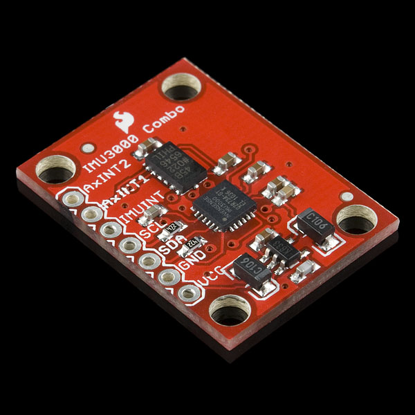
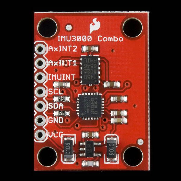
The IMU 3000 breakout features a 3-axis MEMS digital gyro with programmable ranges from +-250 to +-2000 degrees/sec. In addition, it has a secondary I2C port that interfaces with a digital accelerometer to deliver a complete 6-axis sensor output from its primary I2C port. The fusion output offloads the intensive motion processing computation requirements from the host processor, reducing the need for frequent polling of the motion sensor output and enabling low cost, low power microcontrollers.
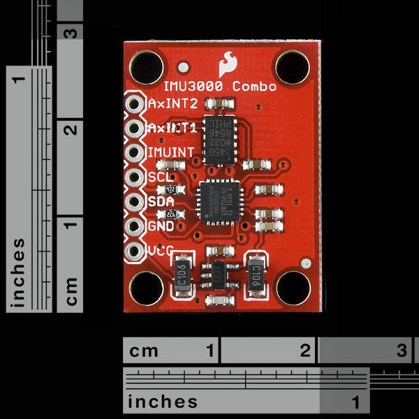
We provide you with a simple board which breaks out the necessary pins on the IMU 3000 and connects an ADXL345 accelerometer to the I2C input of the IMU 3000. There is even a 3.3v regulator as well.
Having a hard time picking an IMU? Our Accelerometer, Gyro, and IMU Buying Guide might help!
Note: The accelerometer on this board is connected to the auxiliary I2C input of the IMU3000 as suggested in the datasheet, in order to allow users who are familiar with the built-in DMP Engine to take advantage of the MotionFusion technology. The board will provide both gyro and accelerometer data as-is but further programming is required to retrieve MotionFusion data.
- Schematic
- Eagle Files
- Datasheet (ADXL345)
- Datasheet (IMU 3000)
- Product Page (IMU 3000)
- GitHub
SparkFun IMU Fusion Board - ADXL345 & IMU3000 Product Help and Resources
Core Skill: Soldering
This skill defines how difficult the soldering is on a particular product. It might be a couple simple solder joints, or require special reflow tools.
Skill Level: Noob - Some basic soldering is required, but it is limited to a just a few pins, basic through-hole soldering, and couple (if any) polarized components. A basic soldering iron is all you should need.
See all skill levels
Core Skill: Programming
If a board needs code or communicates somehow, you're going to need to know how to program or interface with it. The programming skill is all about communication and code.
Skill Level: Competent - The toolchain for programming is a bit more complex and will examples may not be explicitly provided for you. You will be required to have a fundamental knowledge of programming and be required to provide your own code. You may need to modify existing libraries or code to work with your specific hardware. Sensor and hardware interfaces will be SPI or I2C.
See all skill levels
Core Skill: Electrical Prototyping
If it requires power, you need to know how much, what all the pins do, and how to hook it up. You may need to reference datasheets, schematics, and know the ins and outs of electronics.
Skill Level: Noob - You don't need to reference a datasheet, but you will need to know basic power requirements.
See all skill levels
Comments
Looking for answers to technical questions?
We welcome your comments and suggestions below. However, if you are looking for solutions to technical questions please see our Technical Assistance page.
Customer Reviews
No reviews yet.
At hobbytronics, we have written an Arduino sketch for this board. It outputs the Gyro X, Y and Z as well as the Accelerometer X, Y and Z.
You can find it here http://www.hobbytronics.co.uk/arduino-adxl345-imu3000
Do you can help me how to change Measurement Range (g) from that arduino sketch.,.,.,.,. change range from +-2G , +-4G , +-6G ,+-8G, +-16G.,.,.,. please help me.,.,.,
from This Code.,.,. where code to change measurement Range (G)
define GYRO 0x68 // gyro I2C address
define REG_GYRO_X 0x1D // IMU-3000 Register address for GYRO_XOUT_H
define ACCEL 0x53 // Accel I2c Address
define ADXL345_POWER_CTL 0x2D
byte buffer[12]; // Array to store ADC values int gyro_x; int gyro_y; int gyro_z; int accel_x; int accel_y; int accel_z; int i;
include
void setup() { Serial.begin(9600);
}
// Write a value to address register on device void writeTo(int device, byte address, byte val) { Wire.beginTransmission(device); // start transmission to device Wire.send(address); // send register address Wire.send(val); // send value to write Wire.endTransmission(); // end transmission }
void loop() { // Read the Gyro X, Y and Z and Accel X, Y and Z all through the gyro
To date, I can't get this board to work as advertised.
The appeal and "fusion" offered by InvenSense's IMU comes from what they call the Digital Motion Processor (DMP) -- which if I understand correctly is a processor embedded in the gyro's packaging which can turn the raw sensor values into extremely useful and nicely filtered data representations like quaternions and world-corrected acceleration values.
Algorithms that do this well are a pain to write from scratch, and would place a large processing burden on something like an Arduino. The DMP is supposed to do this all for you, and just return a stream of processed data -- you don't even need to deal with the raw gyro and acceleration values if you don't want to.
The problem is that the DMP can not be configured / accessed by manipulating the I2C registers alone. In fact, a bunch of registers are just listed as "reserver for DMP" in the chip's data sheet with no further documentation about how to set up or use the DMP. Instead, you're supposed to use their example code to upload the code for the DMP over I2C (which is a lot more than couple of register settings).
So, as it stands, don't expect to plug this into your Arduino and get any more sensor "fusion" than you would out of a discrete gryo / accelerometer pair. The sketch hobbytronics mention does this, but doesn't use the DMP. Basically, if you want the DMP, you have to use the official SDK code, and that code doesn't (yet) work on Arduino. It also looks like it was written by sadists, it's quite confusing and poorly organized.
It seems like there are two version of the official library floating around. By registering as a developer on the InvenSense site you can download the IMU-3000 SDK, which includes C source for a Visual Studio project intended to run on a Windoes XP computer connected to their evaluation board via their I2C bridge. The other, more promising branch of code looks like an adaptation of the official SDK to run on AVR chips. I spent the better part of a day trying to get this cleaned up and working on an Arduino Uno, to no avail, could never get all three acceleration values to read.
One problem is that the official evaluation board (for which the SDK code was originally written) was intended for a Kionix KXTF9 accelerometer instead of the ADXL345 included in SparkFun's breakout (which means changing a bunch of registers in the code, and possibly some other config settings). Even then, I'm not sure that the DMP code allows you to compensate for the mis-matched axis between the accel and gyro on the SparkFun breakout. (I know SparkFun prefers a smaller footprint to consistent sensor orientation... but it might be a bigger issue than usual in this case.)
So, thus far there doesn't seem to be any way to actually use the advertised functionality of this chip without embarking on a major coding project. Do not expect to "offload the intensive motion processing computation requirements from the host processor" until the software issues are resolved. Until then this board is just a vanilla accelerometer / gyro pair, and if you need to use the DMP functionality (which, again, is the whole point!) you'll have much fewer headaches with the official evaluation board (with the KTF9) than the Sparkfun breakout.
If anyone has had a better experience with this, I'd love to be proven wrong and see some code that gets the DMP to talk.
Eric,
you are absolutely right. Sparkfun should not advertise this board as having on-board sensor fusion when this feature is essentially unavailable due to a lack of support from Invensense. The code provided is a poorly constructed joke that you will not be able to get working on say, an Arduino.
That being said, I did get it to work just fine as a gyro/accelerometer combo. If you're looking for an accurate sensor fusion algorithm that will run on AVR, have a look here:
http://code.google.com/p/imumargalgorithm30042010sohm/
Eric,
This does not look so hard to do; if you have the MPL sources then there are a couple of places that you need to start to hack to get the ADXL345 integrated. I have this board, but then I also have an MPU-6050 breakout too as I have ordered a lot of MPU-6050s from the UK distributor. But I also have an interest in getting this board supported.
This breaks down into a couple of things you need to do:
1. Write an ADXL345 driver for the accelerometer. This will be the meat of the project, but there are examples for the Kyonix and Mantis (6050) accelerometers.
2. Set the accelerometer and gyro orientation relative to the frame. This is done through MLSetAccelCalibration and MLSetGyroCalibration. The documentation isn't of much use because it's not up to date. You are probably better off reading the sources which have better Doxygen comments and poke about in the code. Of course, it would help if you had the reference board to start with to gain confidence in any port.
The problem is not the accelerometer. The problem is getting Invensense's horrible mess of code to compile, let alone run, on anything else than a windows PC. They have an 'embedded' version of this shitpile that does not support AVR and is not available for the general public. I've tried to make it work but no luck there either.
Does anyone know if this board can be attached somehow to a bluetooth mate like WRL-09358 or similar? Thanks.
Bad contact between the IMU3000 and the Arduino was the problem :P
hello… I’m running the sketch from hobbytronics (http://www.hobbytronics.co.uk/arduino-adxl345-imu3000) on an Arduino UNO, but I’m getting only 0’s (“0,0,0,0,0,0”) in the serial port… Not sure about what is wrong…
Got any Ideas?
I just bought this board, and I set it up with the Arduino UNO with 3.3v, and SCL to A5 and SDA to A4. I loaded the Hobbytronics code and it seemed to work except that it outputs all zeros.... I thought I read somewhere that it could be in sleep mode, does anyone know how to fix this?
Perhaps it should be noted that the X and Y axis orientation of the devices are not correct; i.e., use the x axis of the accelerometer as the y axis reading, and vice versa. Additionally, the fusion board has a 5v to 3.3v regulator, but no I2C level conversion...hmmm. Perhaps add a couple MOSFETS to do this and make the board a complete 5v unit, else get rid of the superfluous 3.3v reg, and run the board as strictly 3.3v.
I seriously doubt the on-board sensor fusion will work. IMU3000 takes 16 bit input from accelerometer , while the ADXL345 is only output 10 bit. I don't see how this will ever work.
The ADXL345 still outputs two bytes. It only has a resolution of 10 bits; i.e., only the lower 10 bits are used.
hello...
I'm running the sketch from hobbytronics (http://www.hobbytronics.co.uk/arduino-adxl345-imu3000) on an Arduino FIO, but I'm getting only 0's ("0,0,0,0,0,0") in the serial port...
Not sure about what is wrong...
...I2C address?
...3.3 V input?
should I connect the AxINT2, AxINT1, IMUINT in some specific port of the arduino?
thanks
never mind...
I have the same issue. What was your solution?
Nice, but Atmel sells a 9DOF with the IMU3000 for $54:
http://store.atmel.com/PartDetail.aspx?q=p:10500274
Has anyone gotten the hobbytronics code to work? I'm reading data from my IMU board, but all of the numbers are negative.
-90,-21,-196,-20,2,-36
-92,-22,-197,-26,2,-30
-84,-26,-203,-18,0,-36
-86,-28,-200,-22,4,-34
-93,-26,-197,-26,2,-30
This is a sample. The numbers are GYROX, GYROY, GYROZ, ACCELX, ACCELY, ACCELZ. The board was sitting on my desk, not moving.
the sensors aren't calibrated (or at least they're really badly calibrated) which is probably the reason why your numbers are like that.
Just write a sketch that takes say 100 samples and divides them by 100, and subtract those values in subsequent readings
They're pretty darn sensitive, you really need a graphical representation on a PC to appreciate the outputs properly, wish someone made a processing sketch :/
I made a MATLAB script but who the hell uses MATLAB right?
Engineers use Matlab. Who the hell uses an Arduino?
I do.
Those are similar to what I have been getting. I have yet get any useful data out of these two...
+1...
any news on that? is it just a matter of mapping?
Question / Suggestion on the I2C - Seems that the components on this board, esp. the gyro, are all rated for 3.3V, and Sparkfun was nice enough to put a regulator on board, which means we need to power it with 5V, so wouldn't it make sense to put some logic level shifting on this board for the I2C lines (See Sparkfun product BOB-08745) so they can run at 5V too? Because they really want 3.3V Because as it sits, there's no pad to bypass the regulator if you're running a straight 3.3V system - or am I wrong? Is it OK to run this straight out of the 5V Arduino? Or do I need to go in to the Wire library and turn off the pullup resistors on SDA and SCL? Just wondering.
Is my IMU3000 not functioning properly ??
I am able to clock out the data,, Temperature is absolutely correct, but XYZ gyro data is -67, 70, 112, and plays around those values +-5.
Even when the board is moved, these values do not climb to 1000+ like the ITG3200.
I also notice that the voltage on the CP capacitor is 3v. Isn't this supposed to be close to 30v ??
I am getting similar results for the gyro using the code referred to in the first post: -75, 0, 123. I played with the ADXL345 options and changed it to +/-2g, with MSB and 10bit output. Normalizing the xyz accel data seems to work nicely. My temperature is goofy though, i get negative numbers....
Does anyone has working code for an arduino/avr/pic micro-controllers=
I am unclear what the advantages of this board are - over the evaluation board? (seeing that the price is the same)
http://invensense.com/mems/gyro/documents/EB-IMU-3000-00-01B.pdf
Is the ADXL345 that much better of an accelerometer than the KXTF9?
http://www.analog.com/en/sensors/inertial-sensors/adxl345/products/product.html
versus
http://www.kionix.com/Product-Specs/KXTF9-2050%20Specifications%20Rev%204.pdf
There's also no easy way to add a digital compass to this board either.
It's a shame that the drill holes and headers don't quite line up with a veroboard! nice design otherwise, glad to see the 4 holes, makes it much much easier to have a solid mount
I was just looking at the schematic for this board and have a question ?
Did someone forget to put the pull up resistors on the I2C lines between the 3000 and the Accelerometer ? Aren't they supposed to have a 4.7K pull up on each ?
So, how does it work without these pull ups ?
What a shame, the 'Fusion' turns out to be nothing more than reading the accelerometer data, it doesn't actually do anything!
Any idea when we might get the MPU-6000?
http://invensense.com/mems/gyro/mpu6000.html
Cheers
Yes, when we can have the MPU-6000 breakout board ?
This does more than just read the accelrometer. There is the DMP wich is accessed thrugh the DMP reserved registers of the imu3000.
If you sign in at the product web and look through there documentation they also provide a MPL (motion processor library).
Hello,
They indeed provide some sort of description for their "MPL".
It's just obscur automatic documentation of API calls ...
You have to read the source files of their demo application to try to understand something (I said try ...).
But there is a LOT of work to understand what exactly is done at the I²C bus level to obtain the data ... I just don't have time to RE a commercial product.
I'm pretty sure they have better documentation, but reserved to "tier one" customers (Nintendo ...) and they NEVER answer when you send them a mail.
I'm waiting for the MPU-6000 too, and hope the "DMP" will be usable by the time it's released, until then, I will continue using the ITG-3200.
Regards,
Thomas.
Otatiaro:
It's not clear to me from reading the datasheet what motion filtering the DMP does, and what it's expecting the microcontroller to do.
It would be helpful if SparkFun could clarify what exactly this board does and does not do, maybe with some short sample code.
does this IMU give you the degrees from calibration in each axis? If yes, how would I get it from the gyro? I tried looking through the datasheet....but I don't have a few hours to read it over... :) A tutorial would be nice....
Why not use the BMA180? Is the ADXL345 superior in its accuracy?
I take it that it only works with the ADXL345 (or something very close)? The BMA180 would have made for a tiny board.
Are there any plans to stock/ make a breakout board for the mpu- 6000 as well?
Seconded! A breakout board with an MPU-6000 and a 3-axis magnetometer would be great!
that mpu6000 looks wicked! :) please with spi (easier to level-shift to 5v and faster) (or both spi and i2c) and integrated 3.3v regulator (easy to bypass for ppl who dont need it), maybe even with extra pads (on unused back of pcb for extra smallness) for adding more caps/inductor for cleaner power.
In agreement with the MPU-6000.
Appreciative of this dev board, but it would be silly to use this with the release of the MPU-6000.
Hopefully it won't take as long to push out a dev board for the MPU-6000 with a digital compass.
Very nice! Am I blind or did you forget to put the axis on the silk?
Is there any way to bypass the regulator? I have a 3.3V system.