- Home
- Product Categories
- LilyPad
- LilyPad Arduino Simple Board

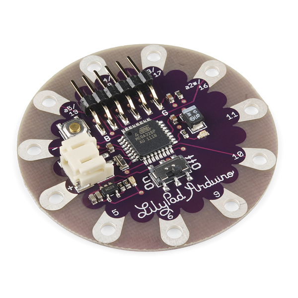
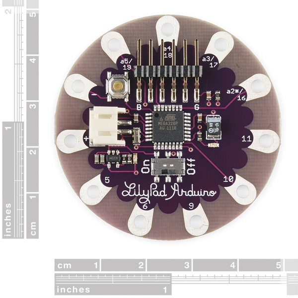
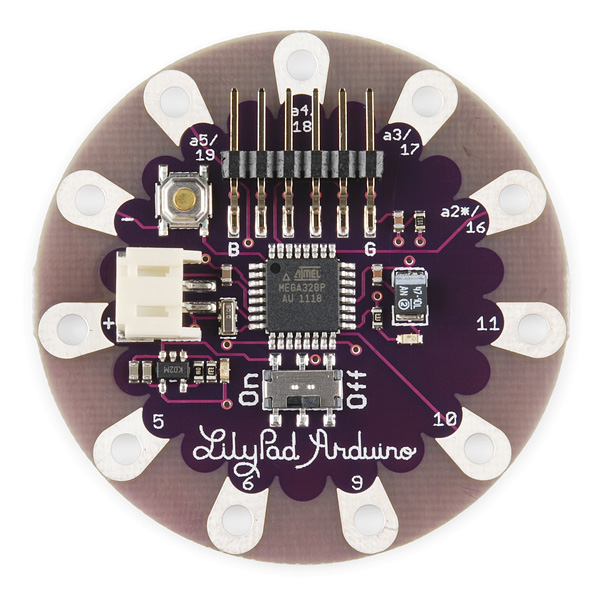
LilyPad Arduino Simple Board
This is the LilyPad Arduino Simple Board. It's controlled by an ATmega328 with the Arduino bootloader. It has fewer pins than the LilyPad Arduino Main Board, a built in power supply socket, and an on/off switch. Any of our LiPo batteries can be plugged right into the socket. The Simple board is designed to streamline your next sewable project by keeping things simple and giving you more room to work and eliminating the need to sew a power supply. This revision does away with the ISP header and adds a charging circuit based on the MCP73831 IC.
LilyPad is a wearable e-textile technology developed by Leah Buechley and cooperatively designed by Leah and SparkFun. Each LilyPad was creatively designed to have large connecting pads to allow them to be sewn into clothing. Various input, output, power, and sensor boards are available. They're even washable!
Not sure which Arduino or Arduino-compatible board is right for you? Check out our Arduino Buying Guide!
Note: A portion of this sale is given back to Dr. Leah Buechley for continued development and education of e-textiles and also to Arduino LLC to help fund continued development of new tools and new IDE features.
Note: Because of the added battery charging circuitry the Simple is unable to power a device from the FTDI header meaning that the Bluetooth Mate, for instance, is no longer plug'n'play compatible.
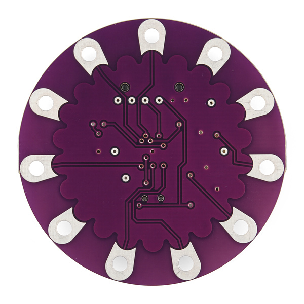
- 50mm outer diameter
- Thin 0.8mm PCB
- Schematic
- Eagle Files
- Datasheet (MCP73831T)
- Leah Buechley's LilyPad Tutorial
- LilyPad Arduino Documentation
- Uploading an Arduino Sketch
- GitHub (Design Files)
LilyPad Arduino Simple Board Product Help and Resources
ProtoSnap LilyPad Development Simple Hookup Guide
September 5, 2013
Interested in getting into LilyPad? Or maybe it's Arduino that tickles your fancy? Just want to add a little white-blinky-LED zest to your vest? All of the above? The ProtoSnap LilyPad Simple is a great tool to explore any of these subjects.
Choosing a LilyPad Arduino for Your Project
October 27, 2015
Not sure which LilyPad Arduino is right for you? We'll discuss the features of each and help you decide.
Light Up Pennant with E-Textiles
September 17, 2015
Show your school spirit, geek pride, or fandom with a light up pennant using the LilyTwinkle or LilyPad Arduino.
Adapting LilyPad Development Board Projects to the LilyPad ProtoSnap Plus
May 24, 2018
An overview of the updates made in the redesign of the LilyPad Development Board to the LilyPad ProtoSnap Plus and how to adapt code written for the old board to the new one.
Core Skill: DIY
Whether it's for assembling a kit, hacking an enclosure, or creating your own parts; the DIY skill is all about knowing how to use tools and the techniques associated with them.
Skill Level: Noob - Basic assembly is required. You may need to provide your own basic tools like a screwdriver, hammer or scissors. Power tools or custom parts are not required. Instructions will be included and easy to follow. Sewing may be required, but only with included patterns.
See all skill levels
Core Skill: Programming
If a board needs code or communicates somehow, you're going to need to know how to program or interface with it. The programming skill is all about communication and code.
Skill Level: Rookie - You will need a better fundamental understand of what code is, and how it works. You will be using beginner-level software and development tools like Arduino. You will be dealing directly with code, but numerous examples and libraries are available. Sensors or shields will communicate with serial or TTL.
See all skill levels
Core Skill: Electrical Prototyping
If it requires power, you need to know how much, what all the pins do, and how to hook it up. You may need to reference datasheets, schematics, and know the ins and outs of electronics.
Skill Level: Noob - You don't need to reference a datasheet, but you will need to know basic power requirements.
See all skill levels
Comments
Looking for answers to technical questions?
We welcome your comments and suggestions below. However, if you are looking for solutions to technical questions please see our Technical Assistance page.
Customer Reviews
No reviews yet.
ola ainda tem o produto??
Yes
What are the PWM pins on this board?
Pins 5, 6, 9, 10, & 11 are all PWM pins.
I'm super new to these stuffs and I've been wondering...do you need a battery for this? Or will it actually charge(and would last) after being connected to a computer? Or does it actually even need a battery to be operable even if connected to a PC?
It looks like in the board layout and the schematic that the application circuit for the charger IC does not power the bluetooth through the FTDI header pins. To get the bluetooth mate working with the LilyPad Simple board, you would need to reroute the pins so that you can provide power to the bluetooth mates https://www.sparkfun.com/search/results?term=bluetooth+mate .
Assuming that you are soldering a 6 pin female right angle https://www.sparkfun.com/products/9429 to the bluetooth plated through holes, you would need to connect the m/f jumper wires https://www.sparkfun.com/products/9140 between the two boards (Tx, Rx, and GND).
For the Vcc pin of the bluetooth mate, you would need to connect it to a power source. Assuming you are using a nominal 3.7V LiPo battery (like the batteries with the silver and yellow packaging - https://www.sparkfun.com/products/339 ), you would just need to connect the Vcc pin to the + pin of the LilyPad Simple. There are a few methods to do this. You could us a m/m jumper wire https://www.sparkfun.com/products/8431 , bend one end to make a sequin, and sew the terminal end to the + pin of the LilyPad . Here is one example of making a sequin using non-standard LilyPad components https://www.sparkfun.com/tutorials/281 .
You can also cut the m/f jumper wire in half, use wire strippers to remove the insulation, and then make an additional sequin out of the wire with the male terminal.
It would have been helpful if there was a link or even a note that a device like the FTDI Basic Breakout would be needed to communicate with this board.
Here I linked it: http://sfe.io/p9716
It's a major disappointment when I'm trying to learn all this stuff and now have to wait for another part to arrive before I can assemble my project. Help streamline this stuff for us by adding the link in the description.
I was checking the schematic and noticed that the R_prog resistor is set to 1K ohm. Is this correct? According to the MCP73831 datasheet, 1K R_prog corresponds to a charging current of 1 amp. This sounds quite a lot and will probably charge the battery too fast. Any idea?
Since this is part of the beginner's kit, I'd like to request that a sentence be added to the end of the first paragraph:
"The charging circuit means the LilyPad Simple will charge the included LiPo battery when plugged into a powered USB port."
I am a beginner, and ordered a separate LiPo charger, thinking it was missing from the beginner's kit, even after carefully reading this description when researching the kit.
So do we need a separate LiPo charger? or just connect the battery and USB port and it will charge the battery along with powering the Lilypad
You won't need a separate charger. Just connect the lipo battery to the Lilypad Simple. The Lilypad Simple will charge the lipo battery when powered by the FTDI basic through your USB Port.
Will this host an XBee board?
Hello.
If the device is connected to a lipo battery, how much power (ma) can be output on the "+" pad? Is it directly connected to the battery, or is it like the regular Arduino +3.3 pin that would have a significant limit on the power it can provide?
Hi everyone, I was wondering if this product will charge the Polymer Lithium Ion Battery - 2000mAh? Also if I'm looking into more power, will it be able to power the Polymer Lithium Ion Battery - 6Ah?
Thanks,
Can this Arduino be used with I2C? I'd like to read analog input from an MMA8452Q, Triple Axis Accelerometer. https://www.sparkfun.com/products/10955
The data sheet doesn't specify I2C pins, like the Lilypad USB, are they still built in?
I am trying to build a simple LED blinking project and it will have to solely operate on the batteries for several hours. I am trying to figure out how long can I keep the project going on the battery. Any idea how much current the board alone consumes?
it really depends on what you're doing. it's going to be pretty minimal though. your best best would be to hook it all up, and then just test how much the current draw is. from there, you can calculate how much battery capacity you need for the desired number of hours.
The addition of the charging circuit is super handy. However, since it's been added it seems that the Bluetooth Mate isn't able to get enough voltage when connected via the FTDI headers. Is anyone else having this problem?
You're right- it won't. The Arduino LilyPad mainboard will work still, so if you need Bluetooth connectivity, you'll have to use that board.
We'll try and fix it in a later rev.
I am trying to use this internal analog reference on this board
via AnalogReference(INTERNAL) command, which i expected to be 1.1v reference, it doesnt seem to be. It still seems to be using supply voltage (which is a pain since I am trying to measure the supply voltage).
Does anyone know whats going on here? Or what the internal voltage ref actually is?
You'll need to lift pin 20 (ARef) - it's tied to Vcc on the board. See figure 23-1 and section 23.5.2 in the datasheet (http://www.atmel.com/Images/doc8161.pdf).
If you are planning on using SPI, as for example with Total Control Lighting, you will need to connect to the SCK pin on what would be D13 on a through-hole on the back of the board. It does not connect to a pad. It is not solder masked so you can solder to it. You can figure out which one it is by tracing from the surface mount LED back through its resistor.
I have managed to solder to this twice on two boards with good results. Then I applied a ton of hot glue to keep the wires from pulling off.
I have a question, I'm an arduino beginner, and I want to use this board, if I use the onboard battery plug for the LiPo battery, should I connect the ground of my components to the negative terminal on this board? Or should I find another ground? How about a Vcc? Should I just use the positive terminal, or should I use a simple digital output (actually, that might be simpler, but the question still remains)? Edit: I found the answer to all of these questions hidden on the LilyPad homepage, connecting the power of other objects to + and the ground to - WILL work as per the example given at: http://web.media.mit.edu/~leah/LilyPad/08_sensors.html)
What is the orange LED next to the on switch? I don't see it in the schematics, but I'm new at this so may be missing it. I'm assuming it has to do with whether the board is running from USB power or battery power? Or whether the USB is currently charging the LiPo battery? It seems to sporadically come on, whereas the green LED on pin 13 is blinking every second as per the basic sketch.
It's just the basic 'power' LED. Check top right on schematic, it's on the voltage regulator.
I just answered a question about the LiPo charging circuit in another product, and your comment made me wonder; You say that the LED (D4) is on the voltage regulator - but it's actually on the mcp73831 Li-Po charge management controller. Specifically, it's on the STATUS pin, which should mean that it does actually indicate charging status?
oh, you're correct, it indicates charging, not power.
Will the simple board be able to power 5 RGB LEDs? Or should I be looking at a different board
Hey, I'm thinking of using a LilyPad Simple board to drive some of the digital LED strips using LadyAda's PWM library. That library uses the ATmega's hardware SPI pins which, on a normal Arduino, are broken out on arduino pins 11, 12 and 13. From the schematic it appears that the appropriate pin does something on the LilyPad simple but is not available for general use? Is it at all reasonable to pull that out somehow?
The SPI pins are always broken out somewhere, it might be a test pad but they are always broken out. The chips come in and are always soldered to the board unprogrammed, so we always need access to the SPI pins to get the bootloader on the board. Check the schematic and Eagle files, I think there are test pins on the board which you can solder to if needed.
URGH - I double checked the LilyPad simple schematic. You are correct in that the SPI SCK is not pinned out. You will be fine with the non-PWM libraries which can use any pins. Otherwise you will have to "skywire" a connection to ATMEGA side of R1. My kids are using the regular LillyPad so they are all set.
It's no problem. Those pins are dual use for GP I/O and an SPI interface. They are available for any use that you have. They are connected to the unpopulated ISP headder in case someone wanted to reflash the default boot code, which you don't want to do. There is no difference between the LilyPad and the standard Arduino in this respect. The LilyPad schematic just has them labeled for both uses. In fact the PWM ADAfruit library uses them as SPI pins so you are all set! LilyPad Simple does not have pin 12(MISO) but this is not used in the library so it's no problem. BTW - it looks like the non-PWM example can use any pins. I got the same ADAfruit RGB strips and will be trying to get this to work this weekend with my kids. They want to wear flashy T-shits at the European Lego Robotics Championship in two weeks (representing the US) so I hope it works! Good Luck.
(I'll repost on the LilyPand Simple product page and the ADAfruit forum in case you miss this)
Whoa, it's in stock and from the April 1st New Product Post. Is it real?
Bill, the parts which are in stock are real. It's not hard to figure out.
I noticed that, just looking for confirmation in case someone ordered one and didn't get their money back 5 minutes later.
For example, there was stock of the IC ressurecting fumes...
Hey Robert, the schematic & eagle files don't match the new board.
Indeed they are not. Could someone at Sparfun fix this?
I believe the discrepancy has been rectified.
For something that will likely attach to clothing, the 6-pin male header looks like trouble; a female header with male-male adapter on the cable would be less snag-prone ;)
Yeah, that was my first thought as well. I think the idea is that the board is mounted "upside down", that is, with the component side facing the fabric. The back of the board is completely flat.