- Home
- Product Categories
- PTH ICs
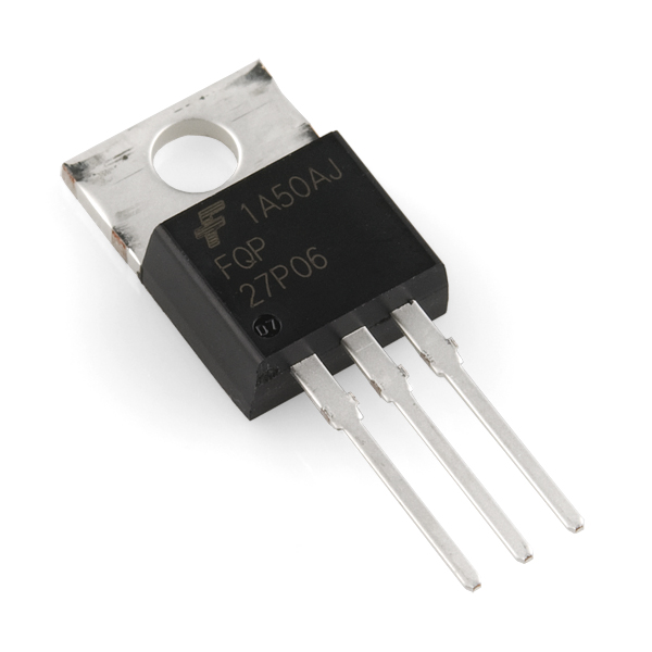
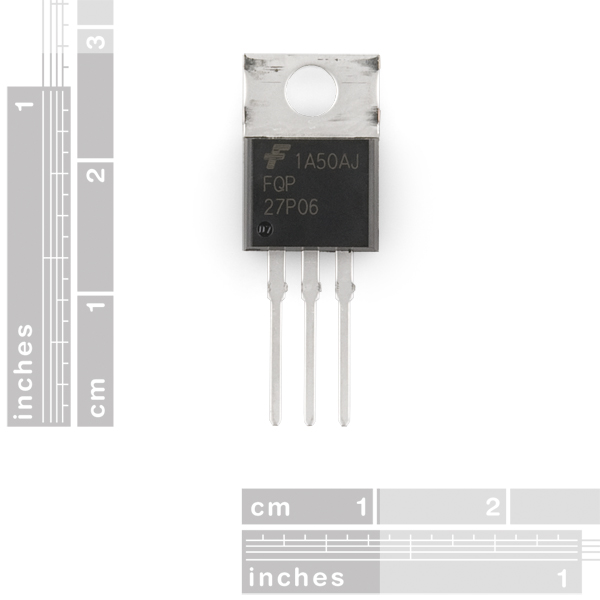
- P-Channel MOSFET 55V 31A

If you've ever wondered how to control the headlight of a car from a microcontroller, a MOSFET is what you need. The IRF5305 is a very common MOSFET with very low on-resistance and a control voltage (aka gate voltage) that is compatible with most 5V microcontroller or mechanical switches. This allows you to control high-power devices with very low-power control mechanisms.
P-Channel MOSFET 55V 31A Product Help and Resources
Core Skill: Soldering
This skill defines how difficult the soldering is on a particular product. It might be a couple simple solder joints, or require special reflow tools.
Skill Level: Noob - Some basic soldering is required, but it is limited to a just a few pins, basic through-hole soldering, and couple (if any) polarized components. A basic soldering iron is all you should need.
See all skill levels
Core Skill: Electrical Prototyping
If it requires power, you need to know how much, what all the pins do, and how to hook it up. You may need to reference datasheets, schematics, and know the ins and outs of electronics.
Skill Level: Competent - You will be required to reference a datasheet or schematic to know how to use a component. Your knowledge of a datasheet will only require basic features like power requirements, pinouts, or communications type. Also, you may need a power supply that?s greater than 12V or more than 1A worth of current.
See all skill levels
Comments
Looking for answers to technical questions?
We welcome your comments and suggestions below. However, if you are looking for solutions to technical questions please see our Technical Assistance page.
Customer Reviews
No reviews yet.
I'm using this in a battery & motor setup to stop accidental reverse polarity (motor running backwards). I'm also using a slide switch. My question is, where do I put the switch - closer to the motor? I'm also wondering if there is any drain off of the battery from the MOSFET when the switch is off.
I just want one of these things.... but dang $4 shipping? Can't ya fire it in an envelope with a $.44 stamp and call it a day? I don't want a $5 transistor!!!!
I see where your comin from but ya gotta check out some other parts too. not only will it make your shipping worthwhile, but you'll get cool parts and support sparkfun!
Is this the same MOSFET that comes with the Official Arduino Starter Kit? http://arduino.cc/en/Main/ArduinoStarterKit
The kit only came with 2. I want to get more so I can experiment with the various logic possibilities but I don't know which to get. The ones in the kit don't say anything about P-Channel or N-Channel nor do they say anything about 60V or 27A. I thought all this stuff was like 5 volts?
Would this mosfet work in this circuit?
http://www.edn.com/design/power-management/4390934/Simple-automatic-shutoff-circuit-uses-few-components
I'm trying to use this PIR module:
https://www.sparkfun.com/products/8630
To keep a load powered for a minute or two after motion is sensed.
(Obviously the capacitor is going to be swapped out for something a little larger.)
I'm looking at using this to control a motor with an Arduino. The power supply for the motor puts out 11.1v. Does this mean I need an additional element to provide the gate voltage, to bring Vgss up to 0v to switch off the MOSFET?
What's the difference between a P-channel and an N-channel MOSFET?
don't quote me on this, im no expert: a p channel mosfet is used on the positive side of the load whereas an n channel mosfet is used on the negative or ground side of the load. When triggered, a p channel mosfet connects the input on the load to the positive source whereas an n channel mosfet connects the output from the load to ground or the negative source.
That's actually a fairly good description of how they're used 99% of the time.
A bit more details: The difference between a P and an N is that an N-channel fet will turn on (aka, conduct) when a voltage greater than the drain&source voltages is applied to the gate, while a P-channel fet will turn on when a voltage less than the drain&source voltage is applied to the gate. Now, in your example, if you wanted to switch something off from the high side (the +5V side), you would use a P-Fet. To turn on the device, connect the gate of the FET to ground. To turn off the device, connect the gate to +5V. This gets a bit trickier when it comes to switching something that needs a higher voltage than what your microcontroller is using, but that can be solved by using an N-fet to invert, then connect it to a P-fet in succession.
Hope that helps.
Not sure if that's correct. As far as I know, a P channel should be used as a high side switch and an N channel should be used as a low side switch but isn't necessarily the case but usually is. Then for both types, an enhancement mode mosfet will be normally on when the gate is high and for depletion mode the mosfet will be normally on when the gate is low.
I was technically correct but because Vgs means totally different things when used on the high side vs low side, it was somewhat confusing. This site: http://www.electronics-tutorials.ws/transistor/tran_6.html has a simple table to reference. Just remember that the source voltage is different depending on whether it's high side or low side. And in my confused state right now, you can probably take it that drain and source voltage is always the same. This shit is so confusing especially when websites try to explain how it actually works. >:D
Can I use this wired directly to the Sparkfun SE-10 PIR sensor, to turn on and off a 20W 12V light? Nothing more intelligent than when signal is low, power to the lamp, signal high power off.
I have bought an off-the-shelf 12v PIR sensor module (one made by Velleman), but there's too big a delay between sensing and activating, for what I want it to do. Seems as if there is an internal relay in the unit that is delaying things. Hence looking at some kind of non-relay option.
With the gate threshold on this at up to 4V, how could I drive several of these using a PCF8575 IO expander? The output voltages are much lower than 4V.
I'm trying to trigger a 12V monitor using one of this P Channel Mosfet.
I have connected the Arduino to the 12V monitor power source, hopping it can power them both, using the Vin pin.
Can someone tell how the wiring should be? should I use a register connected to the gate? what should be the resistance?
Anyone? was that a good choice to take the P-Channel version? am I missing something?
I'll really appreciate your help, as I have all the pieces ready for assembly...
Hey guys! Do remember the basic thermals!
This will heat at 62.5 degree C per watts un ambiant.<br />
This guy have a 0.070 Ohm RDSon.<br />
The maximum temp is 175dC.<br />
Hence:<br />
175-25=150dC of margin for heat.<br />
150/62.5 = 2.4W maximal<br />
P = RI², so: 2.4/0.07 = I².<br />
I = 5.855Amp.
So remember: This will pass no more than a safe 5A over ambiant. Anything above that will require serious heat-sinking.
And that's with the FET turned on well. With a VGS of -5V, the on resistance could be on the order of an Ohm and the available current without heat sinking would be an order of magnitude smaller. You definitely shouldn't expect to get 27 A out of this while controlling it from a 5V I/O pin.
Can i use this for The high side in my hbridge that im making using the N-channel version of this ? When i use the N-channel for the high side they dont turn on all the way .
--Richard
For an hBridge, I would consider keeping N channel.<br />
If they do not turn full on for you, probably you did not gate them with proper voltage.
Might I recommend an IRS2186 or an IR2011 gate driver?<br />
These will give you the proper 12V above Vgs to drive those high side with a big rush of current, and allow for very fast turn-on and turn-off.
Why not something like the IRL520 or IRL540? Those are true logic-level gate MOSFETS?
Sir, these IRL5x0 parts are N channel. This one is P Channel. P Channel is mostly used as high-side on/off switches.
The P Channel need a negative gate voltage to activate. So basically, you pull the gate to ground to activate them, instead of giving it a voltage.
Those IRL parts would be better suited as low-sside switches, where you disconnect the ground from the device, and activate it with a simple MCU IO.
"The FQP27P06 is a very common MOSFET with very low on-resistance and a control voltage (aka gate voltage) that is compatible with any 3-5V microcontroller or mechanical switch."
It looks like you just copied the text from another MOSFET page, but it's not entirely accurate for this MOSFET. This FET has a much higher gate threshold voltage (up to 4V) and will not be on well (or at all) at 3V.
So it will pass a strong 5v though still right?
Right
yep, noted.