- Home
- Product Categories
- Magneto
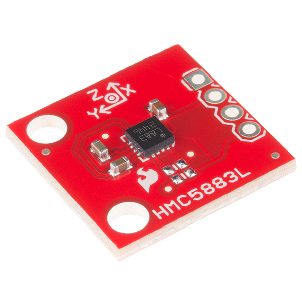
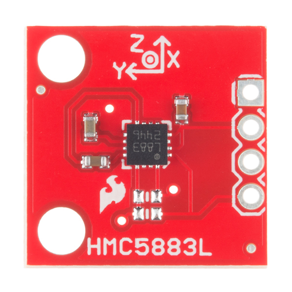
- SparkFun Triple Axis Magnetometer Breakout - HMC5883L

SparkFun Triple Axis Magnetometer Breakout - HMC5883L
Sorry, the HMC5883L went EOL. This part is retired but we recommend the MAG3110 magnetometer or the 9DoF Stick which has a magnetometer built in. Neither are drop in replacements but both will allow you to detect the earth’s magentic field.
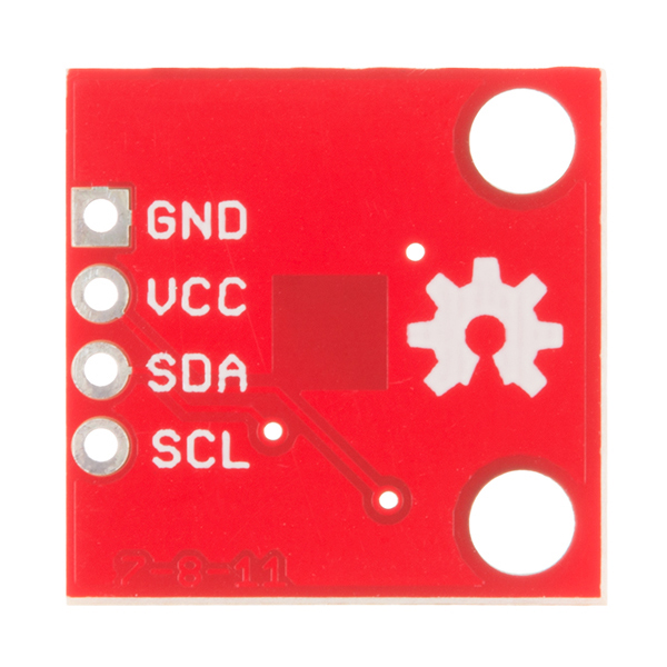
This is a breakout board for Honeywell's HMC5883L, a 3-axis digital compass. Communication with the HMC5883L is simple and all done through an I2C interface. There is no on-board regulator, so a regulated voltage of 2.16-3.6VDC should be supplied.
The breakout board includes the HMC5883L sensor and all filtering capacitors as shown. The power and 2-wire interface pins are all broken out to a 0.1" pitch header.
- Simple I2C interface
- 2.16-3.6VDC supply range
- Low current draw
- 5 milli-gauss resolution
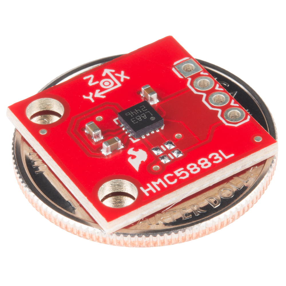
- 0.7x0.7" (17.78x17.78mm)
SparkFun Triple Axis Magnetometer Breakout - HMC5883L Product Help and Resources
Core Skill: Soldering
This skill defines how difficult the soldering is on a particular product. It might be a couple simple solder joints, or require special reflow tools.
Skill Level: Noob - Some basic soldering is required, but it is limited to a just a few pins, basic through-hole soldering, and couple (if any) polarized components. A basic soldering iron is all you should need.
See all skill levels
Core Skill: Programming
If a board needs code or communicates somehow, you're going to need to know how to program or interface with it. The programming skill is all about communication and code.
Skill Level: Competent - The toolchain for programming is a bit more complex and will examples may not be explicitly provided for you. You will be required to have a fundamental knowledge of programming and be required to provide your own code. You may need to modify existing libraries or code to work with your specific hardware. Sensor and hardware interfaces will be SPI or I2C.
See all skill levels
Core Skill: Electrical Prototyping
If it requires power, you need to know how much, what all the pins do, and how to hook it up. You may need to reference datasheets, schematics, and know the ins and outs of electronics.
Skill Level: Noob - You don't need to reference a datasheet, but you will need to know basic power requirements.
See all skill levels
Comments
Looking for answers to technical questions?
We welcome your comments and suggestions below. However, if you are looking for solutions to technical questions please see our Technical Assistance page.
Customer Reviews
4 out of 5
Based on 6 ratings:
1 of 1 found this helpful:
Loving it!
Works with the sketch sparkfun uses as an example, was able to create a 500 lb propane tank level indicator (propane tanks have a magnetic coupled gauge).
1 of 1 found this helpful:
Pull up resistors
The board is missing pull up resistors for the i2c protocol. It would be nice to let people know that they need to supply their own pull up resistors. One can see in the picture where the pull up resistors should be. Perhaps I'm missing something in the reading of this breakout boards description
very convenient
saves making a little board myself, just to try out the chip. Board is good - for me wish it was a little smaller.
Too Complex as a Compass
Had better results with my old HMC6352 as a compass
Super accurate
.. and fast. I would give it five stars, but it could use a non-Arduino code example.
An a great product of sparkfun
This item is very usefull for my projects. I hope shopping very soon. See you!!!
-------------------- Tech Support Tips/Troubleshooting/Common Issues --------------------
One I2C Address
Unfortunately, this sensor has one I2C address. To reduce the number of RedBoards, you might be able to use the SoftwareI2C [ http://playground.arduino.cc/Main/SoftwareI2CLibrary ] to address each sensor on different pins of the Arduino. You can also use the PCA9546A IC [ http://www.ti.com/product/PCA9546A ] to switch between four I2C channels. This chip is ideal when you have a sensor that has only one I2C address. Unfortunately, we do not have the IC available yet on our storefront. I had recommended it to our catalog but I haven't heard back. There is interest but I haven't heard back from our catalog on the details. You would also need to design a breakout board for that chip.
Another Example Code
There's another good tutorial with example code by Love Electronics on their site => http://www.loveelectronics.co.uk/Tutorials/8/hmc5883l-tutorial-and-arduino-library.
Try looking at this tutorial that was written by someone in the community => https://github.com/Razor-AHRS/razor-9dof-ahrs/wiki/Tutorial#sensor-calibration . It goes over how to calibrate the magnetometer that was used on our retired 9DoF IMU [ https://www.sparkfun.com/products/retired/10736 ]. It also talks about what can affect the magnetometer readings when there are soft and hard irons in the vicinity.
Example of HMC5883L's Self Test w/ Calibration
Example of HMC5883L’s self test feature with calibration can be found here => [ https://www.youtube.com/watch?v=Fsd6dAuRURo ] and [ https://github.com/relic1974/HMC5883L_Self_Test ]
Older SparkFun Example Code
Unfortunately, our older example code from this tutorial [ https://www.sparkfun.com/tutorials/301 ] is not compatible with certain versions of the Arduino IDE. It only works with Arduino 0023 or below. Arduino 1.0+ won’t compile with it because the libraries changed. Try using the bildr example code. Otherwise, you would have to rewrite the code a little to communicate with the sensor.
Magnet
Testing with two Neodymium round magnets (with a diameter = 10mm ), the magnetometer can affect the HMC5883L on the Razor around ~22inches (~0.6 meters ) away. The closer the Neodymium magnet is to the sensor, the higher the value was when viewing the magnetometer's raw output.
Very useful, thank you. Does it measure the static magnetic field or oscillating magnetic field? Which range of frequency measure? ELF, VLF, ULF, ...?
Very useful, thank you. Does it measure static magnetic field or oscillating magnetic field? Which range of frequency measure? ELF, VLF, ULF, ...?
I'm shocked !! Honeywell announced End of Life for this sensor and the 5983!!! They have no replacement as far as I know.. especially regarding the 220Hz bandwidth of the 5983.
I just found an app note from Honeywell which states that pin 5 should be connected to VDDIO rather than the no-connect listed in the data sheet. They say it will affect I2C performance in a small percentage of parts if left unconnected. I'm having some I2C hiccups on mine, so I'm going to try adding a jumper.
If there is an opportunity for a design rev of the breakout, adding the pin 5 connection would be good change. As of April 2016, Honeywell has listed this chip as end-of-life, so it seems doubtful that this design will be around too much longer...
There is a good tutorial for this magnetometer over here: hmc5883l tutorial
Not tilt compensated yet, but they say they will do a tilt compensated tutorial soon.
That helps me out a lot! One question
In the tutorial it says to connect it like this:
Arduino A4 (SDA) -> HMC5883L SDA
Arduino A5 (SCL) -> HMC5883L SCL
But I saw that the datasheet said the max voltage
you can apply is 3.3Volts???
Does this mean you need to use 3V3 logic?
((( aka. Use a chipKIT Max32 )))
Or can i connect it to 5Volt logic???
(((aka. Use an Arduino MEGA 1280 )))
Note: The only boards I own at this point in time are:
*Arduino MEGA 1280
*chipKIT Max32
((( By the way SparkFun really needs to... no wait... MUST stock the chipKIT Uno32 & chipKIT Max32!! )))
In the tutorial they power it off 3.3V, and the pull ups are also to 3.3V, so it the chip is receiving about 3.42 - 3.5V on the SDA and SCL lines, I think that should be okay.
So i can plug it directly to arduino without disabling the internal pullups that wire enable by default?
Use a simple voltage divider network on the outputs from your Arduino to the module. AVRs are tolerant of 3.3v inputs, so you should be fine there.
If you have a strong magnet can you use this as a linearized magnetometer to measure distance ? Thanks.
Is it possible to change the address to use multiple HMC5883L on the same interface?
No, unfortunately not. If you wanted to use multiple devices, you would have to have them on separate I2C buses.
When I run the example code I keep getting the error message "Entered scale is not valid...." when executing the library example code statement compass.SetScale(1.3). Within that method, when this error occurs, the regValue will remain the default value 0x00. Can anyone tell me what is wrong and how to correct the error condition? John
Sorry this might be a stupid question, but can you overload this magnetometer? Say if the figures for the magnet were stronger than the limit of this device. I'm trying to measure this magnet buried under the ground for a project. https://www.sparkfun.com/products/8890
Received a few days ago one of these breakout: imagine my dismay when I found out the interrupt pin (DRDY) is not connected! Seriously?
Could we get the drdy pin broken out. I need it for the project i'm making.
Can this be used on a pipe that has flowing water through it, or would that mess with the readings?
While trying to get sane heading readings I found out that the sensors need to be calibrated or else their output will yield very non-linear readings. Here is the process/software I found: http://diydrones.com/profiles/blogs/advanced-hard-and-soft-iron-magnetometer-calibration-for-dummies. Basically, you map the extremes in all orientations and the software creates values to "center" your readings. It makes perfect sense when you open MagViewer and see the scatter plot of the data!
I wonder if someone could post typical X Y values at default gain for NE SE SW NW heading ? Be a big help getting started. Thanks much, Colin
Those values would vary tremendously based on your geographical location, and your location relative to lots of stuff around you. Inside of a building vs outside, near powered train tracks, near overhead power lines, etc. If you want to get an idea of what the magnetic field should look like around you, you need to use the International Geomagnetic Reference Field brought to you by the hard-working folks at NASA and NOAA.
So what about putting it on a pipe with flowing water?
Any plans for an HMC5983 breakout? The 250hz update rate would be nice! It is mostly the same pinout but don't forget to run pin 6 to a solder pad so we can select SPI/I2C.
Also check out the MLX90333 hall effect sensor. It does all the math internally tio implement a hall effect joystick.
Ergh... Wanted a faster read than the mag3110. Got these for their 160hz only to see that the interrupt pin isn't routed. I see comments from 2 years ago about this so I assume we're doomed :-(
I recently purchased the Sparkfun "Triple Axis Magnetometer Breakout -HMC5883L" to use as an external replacement for the internal mag on my APM 2.5
While researching setup info prior to installing the Sparkfun unit I was surprised to find very little info specific to using it as an external on an APM 2.5.
I had assumed that it was common practice to use this board as a 3DR mag substitute and that it would be nearly identical to the 3DR board when it comes to it's setup & use.
I'm perfectly clear and have no questions regarding the physical wiring / correct mounting of the Sparkfun board and I assume that activation & orientation setup will be accomplished through Mission Planner the same as the 3DR unit...
I'm also aware of the advantage that this board has over the 3DR in that it comes 3.3V ready which matches the APM 2.5 I2C
What I would like to know is:
Will there be any code loading Or additional programming necessary with the SF Mag / APM 2.5 setup that is not necessary when installing the 3DR External Magnetometer??
Also,
Anyone aware of feedback from others using the SparkFun Mag as an external on their APM 2.5 & If so, how is the SparkFun board working for them?
I'm assuming that I'm just over-thinking this & the setup will actually be the same or even more straight forward than with the 3DR, but I just want to check first.
Thanks in advance for any help that you can offer.
I am also curious if you got this working.. I think I have a bad compass in my 2.6 APM and was going to go buy one of these at a local SparkFun retailer tomorrow... Very curious if you've been successfully flying with this breakout..
433011, did you get this working? I'm interested in doing the same thing in my Bixler, where I have my APM 2.5 mounted too near some power wiring.
I have an Arduino Nano V3 that is already connected to other I2C ICs that expect 5V, and the I2C lines are pulled up by external resistors. Everything is working fine. I understand that the 3.3V needs to power this chip, but what about the I2C lines? Will they work in tandem to the other I2C devices?
If you have devices that are powered at different levels, you should use a level-changing circuit in your I2C lines. Sparkfun sells one but you can also build one easily with 2 transistors. Look for I2C logic level shifting like this application note pdf.
I'm getting the previously mentioned y-axis no worky. The x and z change with rotation but the y stays around -200 when the compass is rotated like a record player. Anyone figure this one out?
Using this chip breakout board on the Arduino Uno with the example provided I was getting an error at 180 degrees when raw X is less than zero and raw Y is equal to zero. Adding the following "if" statement to the //convert to heading section fixes things.
Hello all I am using this breakout board with arduino atmega 1280 and fez panda ii. On both boards I am geting random values between -3 to +3 (raw) without moving the sensors (actually it does not matter at all it reads the same junk). Somebody help me(Virtual Cop style)
this is what I get
Do you have pull-up resistors on both the clock and data lines? There are solder pads on the PCB to add resistors but the resistors aren't included since many uCs already have pull-up resistors on the I2C bus. Add a 10K pull-up to 3.3V on both lines and it should work.
I had problems with mine at first as well. After adding the pull-ups (5.1K was what I had laying around), worked like a charm ;)
This board/chip is a real disappointing. The data I get from this chip when parallel to the ground is not right. It reads out the Y axis in the Z axis. And each axis has its own scale. Z axis reads from 0 to 512 and X reads from -123 to 173 and the Y axis stays within 280 to 290 when I rotate it around the Z axis. The whole thing is bogus and unreliable. I am going to return it to where I bought it and get another brand. Also the board shows on the schematic that is has the pull up resisters (2.2K) on the SDA and SCL lines. But look at the pictures on the board they are missing! They say nothing about it. The resistors should be right above the 58 markings on the board. Very disappointing!
See my reply to Member #400477 about the resistors. You need to use an arc tangent function with the x and y data to get a heading. Many libraries have an Atan2 function that take two arguments and returns an angle between 0 and 2*pi.
I'm stuck on the same problem, the scales and its X Y axis confused me a lot. I still couldn't figure out what the three dimensions for. About pullup resisters, look at the schemetic on module's datasheet. That's more accurate.
I've never been able to get any useful measurements from this sensor, is there an alternative i2c compass sensor?
Received this yesterday 9/21/2012 and connected according to the Bildr Tutorial, used the example code posted on this page, and everything seems to be working. Raw values on each axis between -4096 and +4096. However, the data sheet and everything else I have read indicates that EXTERNAL pullups are required and the schematic above shows the pullups but the pads on the board are not populated. What am I missing? Why does it work without them?
Thanks
It works because the Arduino Wire library turns on the ATmega's internal weak pull-up resistors by default. This situation will work but isn't ideal; you should really have external pull-up resistors to 3.3V.
hi, last week i received my new HCM5883L magnetometer breakout board , i connected it to arduino according to pin configuration that is SCL to pin 5, SDA to pin 4 with 5.6 k pullup resistor but i received just a raw data between 0 and 5 of x and y and the value of z is constant i-e -4096 , i m not getting what happened to this , whether the board is faulty or there is some other reason.i attached the screen shot of the serial monitor with code. plz if some one knows then help me .thanks in advance
https://mail-attachment.googleusercontent.com/attachment/u/0/?ui=2&ik=58f2ad39b5&view=att&th=13886d0efd4c66b8&attid=0.1&disp=inline&realattid=f_h4n1ptk60&safe=1&zw&saduie=AG9B_P-HEsbSzOf0c1t9f7IJF-lX&sadet=1342878924151&sads=f7oKRGG67IhUfyFUhtBOhr9OEN0
here is the code:
include
// Reference the HMC5883L Compass Library
include
// Store our compass as a variable. HMC5883L compass; // Record any errors that may occur in the compass. int error = 0; // Out setup routine, here we will configure the microcontroller and compass. void setup() { // Initialize the serial port. Serial.begin(9600); Serial.println("Starting the I2C interface."); Wire.begin(); // Start the I2C interface. Serial.println("Constructing new HMC5883L"); compass = HMC5883L(); // Construct a new HMC5883 compass. Serial.println("Setting scale to +/- 1.3 Ga"); error = compass.SetScale(1.3); // Set the scale of the compass. if(error != 0) // If there is an error, print it out. Serial.println(compass.GetErrorText(error)); Serial.println("Setting measurement mode to continous."); error = compass.SetMeasurementMode(Measurement_Continuous); // Set the measurement mode to Continuous if(error != 0) // If there is an error, print it out. Serial.println(compass.GetErrorText(error)); } // Our main program loop. void loop() { // Retrive the raw values from the compass (not scaled). MagnetometerRaw raw = compass.ReadRawAxis(); // Retrived the scaled values from the compass (scaled to the configured scale). MagnetometerScaled scaled = compass.ReadScaledAxis(); // Values are accessed like so: int MilliGauss_OnThe_XAxis = scaled.XAxis;// (or YAxis, or ZAxis) // Calculate heading when the magnetometer is level, then correct for signs of axis. float heading = atan2(scaled.YAxis, scaled.XAxis); // Once you have your heading, you must then add your 'Declination Angle', which is the 'Error' of the magnetic field in your location. // Find yours here: http://www.magnetic-declination.com/ // Mine is: 2� 37' W, which is 2.617 Degrees, or (which we need) 0.0456752665 radians, I will use 0.0457 // If you cannot find your Declination, comment out these two lines, your compass will be slightly off. float declinationAngle = 0.0457; heading += declinationAngle; // Correct for when signs are reversed. if(heading < 0) heading += 2PI; // Check for wrap due to addition of declination. if(heading > 2PI) heading -= 2*PI; // Convert radians to degrees for readability. float headingDegrees = heading * 180/M_PI; // Output the data via the serial port. Output(raw, scaled, heading, headingDegrees); // Normally we would delay the application by 66ms to allow the loop // to run at 15Hz (default bandwidth for the HMC5883L). // However since we have a long serial out (104ms at 9600) we will let // it run at its natural speed. // delay(66); } // Output the data down the serial port. void Output(MagnetometerRaw raw, MagnetometerScaled scaled, float heading, float headingDegrees) { Serial.print("Raw:\t"); Serial.print(raw.XAxis); Serial.print(" ");
Serial.print(raw.YAxis); Serial.print(" ");
Serial.print(raw.ZAxis); Serial.print(" \tScaled:\t"); // Serial.print(scaled.XAxis); Serial.print(" ");
Serial.print(scaled.YAxis); Serial.print(" ");
Serial.print(scaled.ZAxis); // Serial.print(" \tHeading:\t"); Serial.print(heading); Serial.print(" Radians \t"); Serial.print(headingDegrees); Serial.println(" Degrees \t"); }
In the future you'll probably need to use pastebin or some other text sharing site to keep this formatted well (or heck use GitHub! <--- best answer) and then link to that.
What is the resistor size (not value) for the pull ups?
2.2kOhm according to the datasheet.
Hello people
I just got HMC5883L and tried to run the example code. However, I only get the same number.
x: -144 y: -207 z: -286
Does anyone have the same problem ?
Thank you.
I haven't look up the example code, but I think it's probably because the module's default mode is single measurement in mode register.
hello, No, i am getting different numbers by changing the orientation of the sensor. Btw can you tell me what are these values? Are these magnetic field(gauss)? thank you
I love this site.
I was testing this board with Example code and this error message pop up once I click on upload button...
Wire.send() has been renamed Wire.write(). .. As of Arduino 1.0, the Wire.receive() function was renamed to Wire.read() for consistency with other libraries.
Can anyone explain for me where I am and how may I proceed from here?
kind regards, (Arduino-uno)
If you change "receive" to "read" in each of the cases that you see an error, your code should compile again just fine.
has anyone tried this magnetometer with PSOC?, i am having some troubles with the 3 axes signals.
I have been trying to get a reading using an Arduino UNO, but no matter what code I use, even the above example code, the reading output never changes. Could it be the code or the chip? I have tried multiple other codes and they all do the same thing.
is there a version of this example code in Arduino 1.0?
Never mind, I just replaced all the 'Wire.send' and 'Wire.receive' with the new Wire.h commands.
For those who need it, replace all: 'Wire.send' with 'Wire.write' and 'Wire.receive' with 'Wire.read'
Also is it common to have to add the byte() command when sending a 0x00 via Wire.write()? I find it kinda' odd when 0x02 works in the line above it in the example code. Must be some type value translation issue I would guess.
Why 3 dimensions? I understand x,y for N/S and E/W, but how would you use the z axis, especially if it's not tilt compensated?
The local magnetic field isn't just north-south; it also has an inclination or tilt that changes with your location. You can imagine that near the equator the field lines will be roughly horizontal, but as you near the magnetic poles they will tilt higher and higher. If the sensor is held horizontal, the X and Y axes by themselves can be used to determine magnetic north. But if the sensor is tilted at all (and you know the tilt, by using a separate accelerometer), you can use the third axis to compensate for the tilt.
In the example; is the data printed as degrees, radians or Gauss?
The data printed is raw data from the device. You would need to do the math to change this to real-world units based on what the gain register is set to; see the datasheet for details. (Incidentally the result will be in Gauss; this is a magnetometer, not a compass, so it doesn't internally do the math to come up with a field vector.)
Thanks!
Hi, I am new to sensor and this is my first sensor with arduino. i am getting x,y,z with some values. what are these values?can u explain it again for me? Thanks
Can I put 4 of these devices in the same TWI bus? I read over the datasheet but I am not sure if the their inherent addresses can be changed.
This chip does not have address-altering pins like some I2C devices, so you're stuck with the factory address. Sometimes you can get around this by running additional lines to the chip's reset inputs, enabling only the one you want to talk to, but unfortunately, this board does not break out the reset line (sorry).
I'm working on a circuit that will have four of these, interfaced through a PCA9546A I2C mux. I have no idea if it will work, though; these chips generate magnetic pulses to re-magnetize themselves every time they take a measurement; I could see them throwing off each-other's calibration. I will try anyway.
That is a bummer. Thanks anyhow.
If you're feeling ambitious, you might be able to access the reset line from the top of C2, but we haven't tried this ourselves.
Just a heads up - the pin assignments are the exact opposite of the retired HMC5843 (or at least the ground is). I almost bought it for an existing board...good thing I noticed.
Has anyone had any capacitor problems like with the early HMC5843 boards? Did Sparkfun do anything special with the caps on these ones, or are they ordinary garden-variety caps?
I too am very curious what capacitors are used. I can't for the life of me find a 4.7 uF SMD ceramic cap that meets the spec sheet's recommended < 200 mohm ESR.
Digi, Mouser will not list ESR of ceramic caps as they are known to have extremely low ESR (less than 1 mohms, if i remember). So, you are good with any ceramic as suggested in the data sheet. just get something bigger than a 0402.
Is this from a new manufacturer? Or has the old manufacturer started requiring fiducial markers? Or has that always been a requirement and I just never noticed before?
Hi Matt - we are the manufacturer (swing by Boulder some time and you can see us build over 300 different designs). We use fiducials so that the pick and place machines can visually measure the skew on any given PCB. Every PCB is unique and has a few microns or millimeters of adjustment. I think they look ugly but the pick and place guys swear by them so you'll see them on almost every board we design.
I've seen people do "fiducial art" (Spirals, suns, etc) on their boards to mask their ugly appearance. I wonder if you could make Sparkfun-shaped fiducials.
Could we get an Arduino library or possibly some code?
Check the example code above, I replaced it with a PDE sketch.
Thanks, but now I have a new question...
When using the Arduino code above, what would the northern end of a magnetic field be on the z axis?
Also, what would be the best way to use this as a compass that is always level with the ground? (like having a robot with this sensor drive on a very flat concrete floor)
It might be best for you to search around in the forums for how magnetometers work. This will do what you want, but you may need to couple it with an accelerometer for tilt-compensation, unless you can get it level enough.
Ok I'll get out the accelometer....
But what value is the northern end? zero?
For sure you can tell me that.
Considering this is a $1.5 chip in volume, and those caps are probably 1/20th of a cent I'm pretty flawed by the price.
This doesn't even follow the app notes properly which specify there should not be any traces or ground planes under the chip.
There are no traces or ground planes underneath the chip. The Eagle files confirm this.
Do a ratsnest on the BRD file, you'll see that the Eagle file does put a ground plane under the chip, but I doubt this will cause any significant problems. Slowly over time, capacitance from the ground plane could cause problems with the internal clock, but I kind of doubt it. In the same way with a micro controller you shouldn't have a ground plane under the oscillator, you can still sometimes get away with it if your timing requirements are not that precise. In short, yeah, there is no reason for it to be there, but I don't think it's hurting anyone.
As of the one I got Nov 2012 there is no ground plane under the chip.
I am considering this board because I could scrape off the copper under the sensor with a knife or flat screw driver. Also, looks like the trace form VCC misses, but this was probably luck and not careful adherence to datasheet recommendations.
Look at the fourth picture. That large plane-like field on the back, under where the chip would be, sure seems to be connected to that GND pin...
My mistake. I wasn't considering the bottom layer as a potential source of magnetic noise.
If anyone is interested, here is a quote from the datasheet:
"Besides keeping all components that may contain ferrous materials (nickel, etc.) away from the sensor on both sides of
the PCB, it is also recommended that there is no conducting copper under/near the sensor in any of the PCB layers. See
recommended layout below. Notice that the one trace under the sensor in the dual supply mode is not expected to carry
active current since it is for pin 4 pull-up to VDDIO. Power and ground planes are removed under the sensor to minimize
possible source of magnetic noise. For best results, use non-ferrous materials for all exposed copper coding."
Wow, why the high price?
Oops. The system carried over the price from the 5843. Price has been updated. That was our mistake. It's fixed now.
Agreed, that's pretty steep, considering this offers the same as Modern Device's board, which is $16: HMC5883 3-Axis Compass