- Home
- Product Categories
- RF
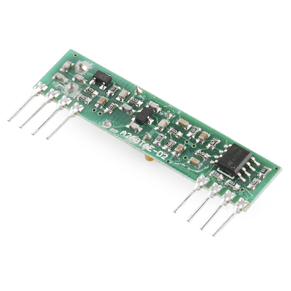
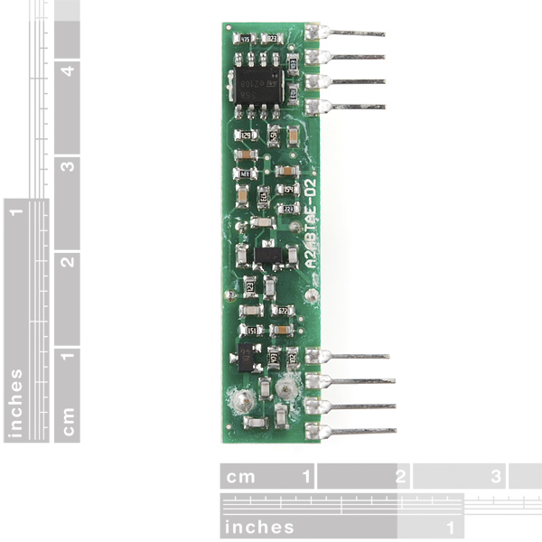
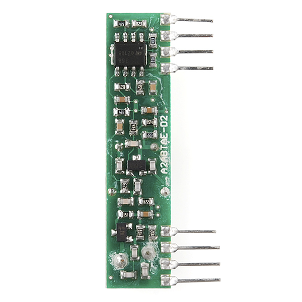
- RF Link Receiver - 4800bps (434MHz)

These wireless receivers work with our 434MHz transmitters. They can easily fit into a breadboard and work well with microcontrollers to create a very simple wireless data link. Since these are only receivers, they will only work communicating data one-way, you would need two pairs (of different frequencies) to act as a transmitter/receiver pair.
Note: These modules are indiscriminate and will receive a fair amount of noise. Both the transmitter and receiver work at common frequencies and don't have IDs. Therefore, a method of filtering this noise and pairing transmitter and receiver will be necessary. The example code below shows such an example for basic operation. Please refer to the example code and links below for ways to accomplish a robust wireless data link.
Note: These receivers are almost identical to the RF link 315MHz receiver. SparkFun does everything in our power to make sure you receive the product you requested. However, if you are concerned you may have received the incorrect product you can verify which version receiver this is by running a simple test circuit.
- 434 MHz
- 500ft range (given perfect conditions)
- 4800bps data rate
- 5V supply voltage
RF Link Receiver - 4800bps (434MHz) Product Help and Resources
Resources & Going Further
Depending on the Arduino library that you use, you could pair this RF Link with an ESP8266 to control wireless remote control sockets that use the same frequency. Here's one project example.
2 of 3 found this helpful:
Testing the RF Link Receiver
To ensure that the RF links are working, we recommend trying to get the RF links working with our example code first. However, I have tested the RF modules with the VirtualWire librarie and Arduino 1.0.6 IDE software. I was able to get it working with this library => VirtualWire 1.20. This library worked with both Arduino 0023 and Arduino 1.0.6.
RF Links
The example code used with the an Arduino microcontroller explains the setup for each RF Link. This is the setup which will work with either RF Link frequency band.
Transmitter Code (4 pin module)
Pin 3 of your Arduino should connect to pin 2 of your RF Link Transmitter 434MHz. Button is connected to the transmitting Arduino on pin 8 separate from the RF Link Transmitter. When a button is pressed on the transmitter, the corresponding LED should light up on the receiver and a character will be sent.
Receiver Code (8 pin module)
Pin 2 of your Arduino should connect to pin 2 of your RF Link Receiver 434MHz. When the button is pressed from the transmitter side, the corresponding LED on this side will light up on pin 8. One thing to note is that the associated LED will not light up on the receiver end if you do not have the associated character to check if it is what is received. An example is if you send a string of characters “Pin 4,” the receiver LED will not light up when the characters “Pin ” is sent. It will only light up when it sees the number “4”.
Note 1: It seems like when the receiver code is compiled with Arduino 0023 that the characters sent show a character and a space right after it in the serial monitor. When compiled with Arduino 1.0.6, you get an hex value and a space that is related to the ASCII character that was sent. You can verify it by checking the ASCII table and it will show that the hexadecimal value that was sent is indeed the character that was sent from the receiver. This has something to do with the shift in versions from Arduino’s 0023 to the Arduino 1.0 and above. Something was modified in the compiler or how a function was defined in the Arduino IDE.
Note 2: The RF Links are cheap wireless modules so you might get some intermittent data transmission/ corrupt data after a certain distance. They have a lot of noise. A better and more secure option might be to use the XBee Series 1 Wireless Modules.
Note 3: I am aware that the Virtual Library is EOL and that the RadioHead library supersedes it. I found out in the middle of updating the code. You shouldn’t have a problem with the library though even though it is EOL.
Core Skill: Programming
If a board needs code or communicates somehow, you're going to need to know how to program or interface with it. The programming skill is all about communication and code.
Skill Level: Rookie - You will need a better fundamental understand of what code is, and how it works. You will be using beginner-level software and development tools like Arduino. You will be dealing directly with code, but numerous examples and libraries are available. Sensors or shields will communicate with serial or TTL.
See all skill levels
Core Skill: Electrical Prototyping
If it requires power, you need to know how much, what all the pins do, and how to hook it up. You may need to reference datasheets, schematics, and know the ins and outs of electronics.
Skill Level: Rookie - You may be required to know a bit more about the component, such as orientation, or how to hook it up, in addition to power requirements. You will need to understand polarized components.
See all skill levels
Comments
Looking for answers to technical questions?
We welcome your comments and suggestions below. However, if you are looking for solutions to technical questions please see our Technical Assistance page.
Customer Reviews
4.1 out of 5
Based on 15 ratings:
1 of 1 found this helpful:
Works!
I used this for a weather station. With an antenna I easily get communication at 20 yards through the house and likely much further (have not tested). Extremely easy to use with the accompanying transmitter.
1 of 1 found this helpful:
Excellent performance over other choices
I tested these against some that I got on Amazon and some that I got on eBay. I found that these (with an antenna of just a hunk of wire) gave me 30 feet more distance than the others. I checked the output on a scope and these had much less noise at a distance where the others gave up. My results will eventually be on our open source home monitoring system: https://github.com/TeamPracticalProjects/SISProject
Handy little RF module
Got these (TX and RX) for an basic wireless project, got them up and running in no time with the VirtualWire library for Arduino (http://www.airspayce.com/mikem/arduino/VirtualWire/).
Awesome for receiving data from Ambient Weather Sensors
I have 8 Ambient Weather sensors located around the house that transmit data approximately once every minute. This receiver works great at picking them all up. Highly recommend.
These are products that cause people to hurt kittens
My bad. I'm new to radio gear. I followed a project that recommended the older superheterodyne receiver. It's been discontinued, but this one hasn't. Turns out this one is a crappy super-regenerative board.
For the minute difference in cost it should have been the other way around. Why sell things that annoy customers, when vastly superior products are available?
This unit is very noise sensitive. My 3D printer washed out the signal, rendering it useless anytime I'm printing.
After looking at a different (forked) project (https://github.com/scruss/Powermon433#user-content-quick-start), I see this is the worst of the 3 types of receivers available. Sparkfun carries the best (https://www.sparkfun.com/products/10154) - but it's 3V and at over 5 times the cost (plus you have to solder in your own headers).
There are superheterodyne receivers available (sadly from elsewhere) that are a drop in replacement. I found one and now I have no more lost packets while printing. Perfect.
Sorry Sparkfun - I like your company, but please replace this (d|r)egenerative unit with a superheterodyne one.
PS: Thanks for taking time to reach out and make my experience better! Looking forward to more little red boxes in the future.
Inexpensive and easy
Great receiver. Easy to get going (I used VirtualWire with an Arduino) and reliable. Very pleased with it, especially considering the price.
Works like a charm
Good service, good product,good,good
Fair good all round receiver.
Well, don't expect to slap some batteries on it a go. Not that simple. With my DSO I was able to create a favorable outcome with a op-amp, a few resistors, capacitors. I guess the best way to approach it is to think " modest control of current" as well as using the op-amp as a simple low pass active filter at all times. An oscilloscope is a must to see if a circuit is working without " false triggering".
Short-range link for Rover control.
Works fine. RWS-371-6 receiver running at 9600 baud about 6 inches apart on a breadboard. Digital signal noisy (5v p-p) with no signal input. Linear signal very small noise with same. With input, digital signal identical to transmitted signal; linear very close with acceptable logic levels. Transmitter is TWS-BS-3. Further separation would most certainly yield better results similar to 315 MHz devices. To address the ID issue, have successfully sent Sync, ID, Data, Checksum packets using Atmega USARTs. Bare bones packet would consist of Sync [0xff] and data. This shorter packet yields better results (less overhead).
Works great - don't forget to add antenna
Works great - don't forget to add antenna
Worked great with the matching receiver.
I used this unit along with the matching transmitter for making a new garage door remote that would also open a gate. Using the radiohead library and giving the transmitter 12 volts, I was getting over 200 feet of range with one antenna behind a brick wall. Better line of sight would have made it even better. These Sparkfun units are worth the money over the less expensive units that are found elsewhere. Highly recommend them and the Radiohead library.
Better documentation would be very helpful!
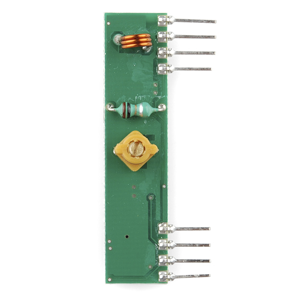
One question is, what is the small pot adjustment for? Is 5 volt the absolute maximum voltage for this device?
Functioned OK but documentation lacking
This receiver did work although I did not test it for distance. I had to go digging for some example implementations as well as example code. The deprecated VirtualWire library worked well although I would like some examples using the RadioHead library.
I rated this as excellent because for the price it is an excellent RF link. This Rx is located in my basement and receives a signal from a Tx in my garage which is approximately fifty feet away. Plus it is simple to wire and easy to program my Arduino UNO to use it.
I have successfully used this with two Arduinos. I was stuck at first, so these points might be of help to others:
1) Using the VirtualWire library linked above is a really good idea. Then you don't have to worry about noise or how the signal is actually transmitted. Simply call a function to send an array of bytes on the transmitter (currently max 27), and call another function to wait for incoming bytes on the receiver. Copy-paste the example code for setup(). It's super easy!
2) The VirtualWire library has a function to set the TX and RX-pin. But do not use pin 10! Pin 10 is assigned as default for something else (PTT, push to talk? I don't know, but probably don't need to know either). You might make it work on pin 10 by assigning PTT to another pin, but I haven't tested that. I just know that it does not work if you select pin 10 for the receiver.
3) There are three GND-pins, and two VDD-pins. My device works fine if I only connect one of the GND-pins and one of the VDD-pins (either is fine).
4) A comment below mentions the need to connect the linear output pin to ground via a resistor to improve signal quality. Perhaps this is true, but I was able to get communication working without the resistor, so don't worry about it to begin with.
I see that the VirtualWire library has reached end-of-life (http://www.airspayce.com/mikem/arduino/VirtualWire/) and now suggests using the RadioHead library (http://www.airspayce.com/mikem/arduino/RadioHead/). They mention SparkFun on their page of places with compatible hardware, but they don't mention this one in particular.
Which radio class does this one fall under?
The docs say RH_ASK is the class to use, but I haven't been able to get it to work.
Did you ever find out how to get the RH_ASK to work?
^ Was just updating some of the example code in our GitHub repository that was using the library. In the middle of it, I found out the VirtualLibrary has been superseded by the RadioHead library as you have noticed. I will be looking into this issue and will need to test the code out when I have more time to update the code again.
I'm not sure what you mean by radio class?
For more tutorials on the RF link modules:
http://www.glacialwanderer.com/hobbyrobotics/?p=291
http://letsmakerobots.com/node/12336
http://winavr.scienceprog.com/example-avr-projects/running-tx433-and-rx433-rf-modules-with-avr-microcontrollers.html
http://narobo.com/articles/rfmodules.html
Can you read signal strength with this? If so I would like to try using a pair to get a bearing on the transmitter.
I don't believe the RF Links have the capability to be a Received Signal Strength Indicator (RSSI). An XBee has the capability of outputting some RSSI data I believe => http://forum.arduino.cc/index.php?topic=178481.0 and https://davidbeath.com/posts/reading-xbee-rssi-with-arduino.html.
Can one receiver get data from multiple transmitters (WRL-10534) if some sort of an address byte is assigned to a transmitted piece of data?
Yes
at the same time??
From description: "Note: These modules are indiscriminate and will receive a fair amount of noise. Both the transmitter and receiver work at common frequencies and don’t have IDs." Keywords: Indiscriminate, don't have IDs
You have to write your own code to handle packet routing and to make sure the signals don't overlap, so yes: One receiver can get data from multiple transmitters and/or basically other device operating at the 434MHz frequency.
Quick question on this module. Would it be decent in a High Altitude project with an amplifier and filter on the antenna?
I have been trying to get a small project working using an RWS-371-6 receiver and the matching transmitter to activate a small 3.5V hobby motor, using 3 AAA batteries for the receiver. Unfortunately I cannot get it to run reliably. I think I am getting noise from the motor that is effecting the receiver but I don't know for sure. Does anyone have an example of a reliable circuit for remote control of a small 3-5V DC motor or can you share some advice? I have tried all of the various noise cancellation techniques with various capacitors...no luck. And, yes, I am using the Mfg's reference diagram, just in case you were wondering.
HELP?!
I just accidentally put 11.1v down my 5v rail. Arduino is toast, so I know I'll be ordering another one of those, but I'm wondering if I need to get another one of these too. Unfortunately, I don't have another arduino to test it with. Is there a way I can test this without a microcontroller? (So I know for sure whether to order another?)
I don't have access to a scope, but I was wondering if it were possible to approximate signal strength from the linear out with this setup. Has anyone looked at the raw output? What exactly does it correspond to?
If I already mess up with the calibration of the module; how can I calibrate it?
Build a remote control car from ground-up without a microcontroller! In this series of videos, we will outline a step by step tutorial on building a remote control car (using RF transmitter/receiver like this one here).
In our first video of this series, we will look into controlling LEDs using an encoder/decoder pair. The schematics is on our Facebook page: https://www.facebook.com/pages/Soapbox-Robotics/813970705334058
This video is live on Youtube: https://www.youtube.com/watch?v=ctkbtYnofcI
I have just used this receiver with a passive infrared alarm module, a Quorum A-160, The modules are sold by Electronic Goldmine, contain a PIR, and 434 MHz transmitter and an encoder. The problem with them was that no one could seem to locate the companion A-160 receiver. I used this receiver module and scoped the output to get the encoding, which seems to operate at about 1000 baud. The interesting thing is that the transmitter module encoding was apparently originally used to set the transmitter to the receiver and any sensor would set off the receiver indiscriminately. By decoding the address I was able to make a zone alarm using multiple transmitters whose location was decoded by the receiver with an ATTiny85. The protocol seems to be a bit non-standard, but it is a fairly trivial matter to decode it. The receivers work well, I have gotten 70+ feet through two walls with them.
The available data on this unit is very sparse. Checking the data sheet, there is no: -Schematic of the unit -Mention of what the screwdriver adjustment is for -Mention of how the linear output is derived from the digital signal. -What limits the data rate to 4800bps
Not absolutely sure, but it appears that 4800 maximum is a result of the frequency response of the components - the waveform is beginning to degrade significantly at that rate when viewed on a scope.
I recently built a project with this part. I accessed data from a La Crosse TX6U temperature sensor.
Check out the blog post I did, and you will find the code too.
http://biancarelli.org/blog/2014/07/27/fun-with-a-tx6u-temperature-sensor/
Ernie
is this beaglebone compatible?
Would I be able to use many of these to wireless transfer information between sensor nodes and a main processor? Would I be able to use the same frequency to communicate in the reverse direction, assuming that I created a "syntax" of communication?
So I want to create a magic sword, like sting, that lights up in the presence of certain things. could this be used in conjunction with the transmitter to trigger EL wire?
Can you have one transmitter and about ten receivers?
Sure! The more, the merrier.
Are you not suppose to obey FCC rules with this device which mandates only short transmission times with this device? SEE: https://www.linxtechnologies.com/resources/documents/fcc_resource_document.pdf ALSO: https://www.linxtechnologies.com/resources/documents/an-00125.pdf If you want to achieve proper reception with this device you should use an encoding scheme such as Manchester encoding as well as send some throw away data first such as 0xAA s to sync up the receiver to the transmitter. SEE: https://www.linxtechnologies.com/resources/documents/an-00160.pdf
What's the recommended decoupling cap value to use with these (or is that completely dependent upon the application)? Also, I'd like to use these with a 9N1 UART scheme - am I barking up the wrong tree, or will that work?
Is there a difference between the 315MHz and 434MHz versions of this? (Not in the physical product, but in the range, quality, etc.)
Is it safe to supply 4.5 volts, or 6 volts to this receiver?
I think this is the receiver with the worst performance I ever bought.
These work best with 13cm of wire connected to the antenna pin.
FWIW, I wrote a node library that interfaces with the RF link receiver and the accompanying WRL-10534 transmitter. It's not much, but if it helps anyone, great! http://kenhirakawa.com/one-way-rf-communication-with-arduino-and-node/
What are the power requirements for this? I built a project with one of these a Pro Micro - 5V/16MHz and ONE LED. I am powering it with a bank of 4 AA batteries.
The LED goes on when I am on the phone so the LED is on about 30 minutes a day.
The batteries lasted one week. Is this normal?
I haven't measured this part specifically, but you can get a good idea just from the numbers you gave.
A week is 168 hours. AA batteries are in the 2500mAh range. Dividing gives us an average current draw of 14.8mA.
I would expect the Pro Micro to be in the 10mA range, so the RX and LED raising it to 15mA sounds about right.
Mike,
Thank you for the quick response! Goin rechargeable!
Thanks!
Great idea!
Hi, I also have a Pro Micro and a TX&RX433. I try to use the virtualwire librairie but I am unsuccessful. Did you used it ? Did you do some adaptation ? thanks
Does anyone know of a trick to grab a RSSI from this component? Thanks!
I'm unimpressed with the datasheet. Tinkering wiht this module, it appears that pin 1 is power ground, and pins 6 & 7 are RF ground. Something to keep in mind if you're trying to build a clean circuit...
Actually, looking the datasheet over I'm wondering if the "Linear Output" would work if I brought it to a ADC pin. Has anyone tried this?
Is this receiver unidirectional or omnidirectional?
Is it legal to use this frequency in Canada?
Anybody know if this is compatible with the universal RF remote (i.e. garage doors etc)? I'm tempted to build a project if it is, as my new car has three universal remote channels I can program... and I don't have a garage.
I discovered that these units work better without the antennae than with them, at least at a distance of 4 meters or so. I also discovered that I needed to tie the "Linear Output" pin to ground via a resistor, 200K or so, otherwise the reception was horrifically unstable.
Just got one of these to debug a wireless project I'm working on. I bought a set of wireless outlet switches on Amazon (has a remote and 5 boxes that plug into the wall, each with a relay to switch an outlet on or off). I took the remote apart and it had a 433MHz radio. I scoped the protocol and it uses an equal-spaced long/short encoding. I figured this 434MHz would be close enough and it is. The thing outputs random noise until I press the remote button, then I see the signal perfectly. I also bought the 434MHz transmitter which I will use to mimic the remote to control the outlets. A lot of commercial stuff uses the 433/434MHz band so that is another possible source of noise, but most are not steady connections, only momentary.
What part number is this in the Sparkfun Eagle library?
What is the maximum amount of current that this thing draws when it is under maximum load? I'm trying to figure out if I can run a circuit off of the supply voltage given from the FTDI breakout board.
Has anyone got this to work at 4000bps? My design works perfectly with a slightly older model, so I thought this part would be a drop in replacement (yes, I verified it is the same pinout and the same operating frequency). I measured the output with a logic analyzer, and found that all the falling edges seem to be lagging -- almost as if an RC time constant is too high in the rectifier circuit... It is enough to cause bit errors and dropped packets. It is frustrating because these parts are supposed to work up to 4800bps.
You should have the "Arduino Library" point to Mike McCauley's site so that you can download the latest version rather than pointing to the old VirtualWire 1.5 version (which doesn't compile out-of-the-box on Arduino 1.0).
At the time of this comment, the lib is up to 1.9 and compiles on Arduino 1.0 out-of-the-box.
Another good link is this one for a wireless RF temperature sensor project using two Arduinos. He doesn't use VirtualWire though it is informative.
guys pls check out the example code with ur arduino and pls tell me wen u pres the button on ur transmitter does the led on receiver light up constant or does it flicker or blink?? pls guys tell me this is the most imp the im gonna make with this!!
Is this capable of receiving signals from weather stations that use the 433 MHz band or is the modulation (or some other aspect) incompatible?
Hi, I built a break out board that holds 2 receivers, 315 and 433 MHz. I added an extremely simple support circuit, and voila! Perfect data, every time. There isnt a and RF remote in my house I cant read perfectly.
Its a beatiful board, 4 basic extra components. If Sparkfun is willing to make the board (and share the Loot), Ill gladly share the circuit. However, I think i might be willing to do it if you put my name on the silk screen!
I wish there was a way to post pictures...
I have been having trouble getting these things to work properly. Can you describe what you did to make these work?
Can you please give the me circut
Look at "Data Slicers" (hint: Comparator) ... Hook one up to the RSSI output.
Would anyone care to see the output of theese on an oscilloscope?
i can send some binary data and do some graphing on both the Linear out, and the digital out pins.
Sorry though no Spectrum Analyzer yet :/
http://mbed.org/users/4180_1/notebook/ir-and-rf-remote-controls/ has a code example for mbed sending characters from the matching transmitter to this receiver.
Could I send a one-bit (on/off) signal without encoding, virtualWire? Basically, without a uC. I just want an LED to turn on connected to the receiver when a button is pressed on the transmitter. Is this possible?
Testing here, it seems that the receiver outputs a high (lit LED) by default, goes low when the transmitter sends low, and then drifts back up to high after a second or two. No chips, only buttons/resistors/LED. I read somewhere that this receiver adjusts input gain until it gets something, which might explain the drifting high.
Use an HT12E (encoder) and HT12D (decoder) or similar ICs no need for uC.
Anyone has the Eagle library for this?
Also, I see a lot of people having trouble with the transmission. I used these in a project and I'm planning to use them again in another, and that's because of the HT12-E HT12-D pair of Enconder and Decoders (that also appear in these devices Datasheet).With the IC pair they worked perfectly, the only drawback is that if you are really worried about hardware, you'll have to use a 18 pin IC.
I have been using these to build a remote robot. The transmitter and reciver are controlled with two Arduino UNOs. I have a test where it reads a message transmitted from the transmitter(WRL-10534
) and prints it on the screen. I have that part working somewhat perfectly. When a motor is attached(anywhere, even on 5V and gnd pins) the data gets completly messed up, no usable information. Does anyone know how I could fix this?
One of two things could be happening. Either A) when the motor kicks on, its generating a lot of noise on the DC supply to the RF module, which causes the module to do all kinds of freaky things. B) The RF module is too close to the motor and is picking up the electromagnetic field generated in the motor's coils. Connect an oscilloscope to the power supply for the RF module, monitor the signal when the motor kicks on. If you see a huge spike or even noise, add a simple filter between 5V+ and RF V+. A filter could be a simple 1+ Ohm resistor feeding a 1000uf and a 0.1uf capacitor, with the RF module being powered by the caps. Increase the resistance of the resistor until the noise goes down enough to prevent the problem, while still feeding the caps with enough power to keep the module on. Then test the data pin. If the noise is only on the data pin, then you need to move the RF module further from the motor and possibly try to shield it from EMI. Also make sure you are decoupling everything, and if you have ferrite beads, use them on the motor's wires.
I bought a couple of these, and both seem to have a constant stream of output coming from both. With no input to the transmitter (even with it not powered) I still get a steady stream of bit flips out of each one on the receivers. I've double checked the wiring to each (all Vcc and Gnd present) and still cannot find where the issue is. Has anyone else seen the same issue?...
These are extremely basic transmitters and receivers, and thus you cannot just put digital or serial data in one end and have it come out the other. The signal you put in (and get out) must be modulated; that is, it needs to change state (low to high, or high to low) at least every 30ms, or the receiver will not be able lock onto the signal. When there is no valid TX data, the RX will output noise, so the TX modulation must be constant, even when there's no actual data being passed. (And ideally the modulation should be balanced (equal time high and low), see line code for more information, Manchester encoding is a popular choice.)
See the links above for examples on how to work with these parts; they're an inexpensive and effective solution if you're willing to do the work that more expensive parts do for you.
Mike, thanks for the quick response!...and that's super great information to have about how the transmitter receiver pair operates. Unfortunately, knowing that now complicates my project a bit, but not a brick wall. Now, is that info also somewhere in the documents linked above for the receiver that I was completely blind to?...well, I suppose if not, it's here now. Thanks again!
All of the linked examples use modulation to some extent, but you're right that this requirement is buried in radio theory to the point of obscurity (sorry about that!)
One way to get these working is to constantly send a character across (0xAA is a good choice since in binary it is "10101010" and thus has lots of transitions), and ignore that character at the receiving end. Then you can slip in other characters that are your "real" data as you have it. (You could even check for the 0xAA and use it to prove that a link is actually established). Hope this helps, good luck!
I guess I have the approximately opposite problem from n0mad. I see no activity on my receiver's data pin -- ever. The transmitter and receiver are wired correctly and I am using only example code at this point. It appears that the transmitter (as far as I can tell) is spitting out data right beside the receiver. In desperation, I tried "tuning" the receiver but there was no change. Very frustrating. Does anyone have any ideas how I can debug this? Is there any way to find out if the transmitter is actually transmitting (when one does not see anything on the receiver)?
Double-check your power and data lines (right voltage, right pins), and if that doesn't help, consider posting on the SparkFun forums.
Yes I have the exact same issue as you sadly :(
It would be nice if Sparkfun had Datasheets for the product they actually ship. The one they sent me does not match the link above. It doesn't even match the picture.
You get what you pay for holds true for this little gem. Thinking that an xbee would be overkill to transmit a 4 byte message, I decided to try this product. I purchased one of each flavor. Both 315 and 433 Mhz radios produce nothing more than a continous stream of noise that no amount of software, checksums and programming can reliably filter out. I am lucky to get 1 good 4 byte message out of 20 transmits.
I have this. At first it was unusable. After I figured out some tricks, I got it to work pretty well.
if its used in railway track fault identification applicable possibilities is there?
Think this will work with the TI Chronos?
No, the TI Chronos uses a different wireless protocol.
Protocol, Frequency and Modulation- 3 diferent things.
If the Chronos is transmitting at 433 MHz, this reciever will pick it up.
If the Chronos is FSK instead of ASK, it wont work.
Understanding the data format (the protocol) is a different story.
... just for clarity sake.
ah good thing the deal ran out. I tend to see more cons to buying a product when I can't have it :P
Dunno if this is on purpose or not, but the example code is missing the closing */ on "TRANSMITTER CODE" and "RECEIVER CODE" which effectively comments the entire thing out so you don't get any syntax highlighting/etc.
So glad this is back.