- Home
- Product Categories
- RF
- RF Link Receiver - 4800bps (315MHz)

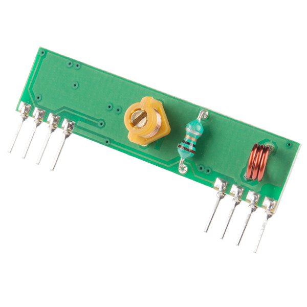
These wireless receivers work with our 315MHz transmitters. They can easily fit into a breadboard and work well with microcontrollers to create a very simple wireless data link. Since these are only receivers, they will only work communicating data one-way, you would need two pairs (of different frequencies) to act as a transmitter/receiver pair.
Note: These modules are indiscriminate and will receive a fair amount of noise. Both the transmitter and receiver work at common frequencies and don't have IDs. Therefore, a method of filtering this noise and pairing transmitter and receiver will be necessary. The example code below shows such an example for basic operation. Please refer to the example code and links below for ways to accomplish a robust wireless data link.
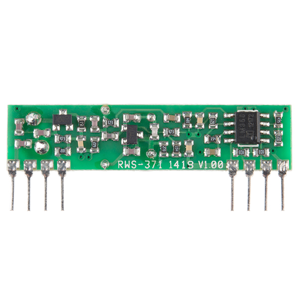
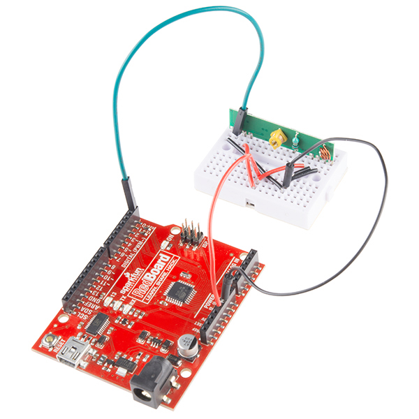
Note: These receivers are almost identical to the RF link 434MHz receiver. SparkFun does everything in our power to make sure you receive the product you requested. However, if you are concerned you may have received the incorrect product you can verify which version receiver this is by running a simple test circuit.
- 315 MHz
- 500ft range (given perfect conditions)
- 4800bps data rate
- 5V supply voltage
RF Link Receiver - 4800bps (315MHz) Product Help and Resources
Testing the RF Link Receiver
To ensure that the RF links are working, we recommend trying to get the RF links working with our example code first. However, I have tested the RF modules with the VirtualWire librarie and Arduino 1.0.6 IDE software. I was able to get it working with this library => VirtualWire 1.20. This library worked with both Arduino 0023 and Arduino 1.0.6.
RF Links
The example code used with the an Arduino microcontroller explains the setup for each RF Link. This is the setup which will work with either RF Link frequency band.
Transmitter Code (4 pin module)
Pin 3 of your Arduino should connect to pin 2 of your RF Link Transmitter 315MHz. Button is connected to the transmitting Arduino on pin 8 separate from the RF Link Transmitter. When a button is pressed on the transmitter, the corresponding LED should light up on the receiver and a character will be sent.
Receiver Code (8 pin module)
Pin 2 of your Arduino should connect to pin 2 of your RF Link Receiver 315MHz. When the button is pressed from the transmitter side, the corresponding LED on this side will light up on pin 8. One thing to note is that the associated LED will not light up on the receiver end if you do not have the associated character to check if it is what is received. An example is if you send a string of characters “Pin 4,” the receiver LED will not light up when the characters “Pin ” is sent. It will only light up when it sees the number “4”.
Note 1: It seems like when the receiver code is compiled with Arduino 0023 that the characters sent show a character and a space right after it in the serial monitor. When compiled with Arduino 1.0.6, you get an hex value and a space that is related to the ASCII character that was sent. You can verify it by checking the ASCII table and it will show that the hexadecimal value that was sent is indeed the character that was sent from the receiver. This has something to do with the shift in versions from Arduino’s 0023 to the Arduino 1.0 and above. Something was modified in the compiler or how a function was defined in the Arduino IDE.
Note 2: The RF Links are cheap wireless modules so you might get some intermittent data transmission/ corrupt data after a certain distance. They have a lot of noise. A better and more secure option might be to use the XBee Series 1 Wireless Modules.
Note 3: I am aware that the Virtual Library is EOL and that the RadioHead library supersedes it. I found out in the middle of updating the code. You shouldn’t have a problem with the library though even though it is EOL.
Core Skill: Programming
If a board needs code or communicates somehow, you're going to need to know how to program or interface with it. The programming skill is all about communication and code.
Skill Level: Rookie - You will need a better fundamental understand of what code is, and how it works. You will be using beginner-level software and development tools like Arduino. You will be dealing directly with code, but numerous examples and libraries are available. Sensors or shields will communicate with serial or TTL.
See all skill levels
Core Skill: Electrical Prototyping
If it requires power, you need to know how much, what all the pins do, and how to hook it up. You may need to reference datasheets, schematics, and know the ins and outs of electronics.
Skill Level: Rookie - You may be required to know a bit more about the component, such as orientation, or how to hook it up, in addition to power requirements. You will need to understand polarized components.
See all skill levels
Comments
Looking for answers to technical questions?
We welcome your comments and suggestions below. However, if you are looking for solutions to technical questions please see our Technical Assistance page.
Customer Reviews
2.9 out of 5
Based on 7 ratings:
3 of 3 found this helpful:
These work quite well
These work quite well...but you have to know what you're doing. RF receiver modules are sensitive to noise typically present on the power rails of solderless breadboards. On top of that, you need to develop a data transmission protocol that “conditions” the RF receiver module for receiving data, allows the receiver to recognize valid data transmissions, and includes error check byte(s) to ensure the integrity of the data. The manufacturer could be more helpful by providing application information that covers those topics.
2 of 2 found this helpful:
Twice sent wrong product in the correct packaging (mis-labeled)
Finally getting around to writing this review. The review is for Sparkfun in general since they never sent me the correct product. I ordered the 315MHz transmitter and receiver. When I received the products I tried several times to read my remote control signal. Never worked. When looking up the data-sheet based on the PCB (RWS-371-v1) I realized they sent me the 433MHz. I emailed them several times and did an online chat twice. It took over 4 months for them to send out the replacement once I told them the wrong item was shipped. When I received the replacements, the package showed WRL-10533 (the 315MHz), but again it was the 433MHz (RWS-371-v1). I confirmed it by transmitting on my 433MHz transmitter and was able to read the signal on the receiver. It will take a lot for them to redeem themselves. I lost the contract because I could not finish my prototype device.
Tricky, but effective
I got this working fairly easily using the KLP Walkthrough Tutorial linked in the item description. There is one major gotcha, however: the tutorial says that Pin 3, the "Linear Output/Test" can be taken to ground. I found that this really needs to be left disconnected, or the receiver won't work at all.
Filtering is also very important, both in the analog domain around the part and with the digital data in your microcontroller. You will definitely get junk and missed characters, so a robust messaging scheme is critical.
Poorly documented and fails to work out of the box
This was purchased as a pair: the RF Link Transmitter - 315MHz and RF Link Receiver - 4800bps (315MHz). When placed on two boards, and gave ground to the GND pins, 5V to the VCC pins, and data on the transmitter pins, I was unable to find out which pin on the receiver to use to read in via my Arduino. I followed several tutorials but none of them had the same transmitter or receiver as this. It was labelled as the same, but the pictures in the video didn't match. Nor did the pinouts. So who knows. However, I tried both pins on the receiver. When giving 5V to the transmitter data pin, nothing changed from what came out of the data pins of the receiver. I then tried soldering on 13cm wires to the antenna pins, per several sites, coiling the antenna on the receiver and keeping it straight on the transmitter. Still no change. All I read was 1.32V on the receiver whether the transmitter had 5V on it's data or 0V. The datasheets offered no help. I wanted to try VirtualWire, but if the primary analog voltage functions did nothing, VirtualWire wouldn't even be worth a test. However, I did try it, just in case. No surprise, it didn't work either.
So, in short, I understand the transmitter and receiver is only a $7 purchase, plus shipping when put together, but I would at least expect them to work somewhat, rather than not at all. It is a waste of time. Buy more expensive ones elsewhere that has solid documentation.
Sorry to hear that. I would suggest getting in touch with our tech support team, they should be able to help you resolve these issues.
Bring back the RoHS version
I used this to capture the signal from a fixed-code garage remote. It works very well, but I'd love to have a RoHS version.
0 of 1 found this helpful:
Unsuccessful Startup
After trying several scenarios to get the 315MHz transmitter and receiver to communicate and being unsuccessful, I set them aside for maybe another day. I followed the application notes in their very basic form and nothing worked. Unless the application notes are reviewed for errors and communicated to me, I will not used the 315MHz RF Link transmitter and receiver.
Very sorry for the troubles with these modules. I have not personally used these in a number of years. I will recommend that we review these items for update when we can.
How can i measure the RF signal power with this module?
rf link 4800bps receiver - (315mhz): Placing a 1M ohm resistor between data out and ground on this device was the only way it would receive for me. Just mentioning this here because I only found one obscure post pointing to this being an issue in a forum somewhere when I was googling for a solution. Excellent cheap wireless option. Thanks for feeding my addiction Sparkfun!
Has anybody tried these with WRL-08945? Will they work with WRL-08945?
What is the screw used for? I am probably not the only one wondering if you need it to tweak your receiver (and probably also not the only one who turned it around a few times before asking this question :S). Anyone an idea?
I am getting horrible connection at >5m, even when I boost the transmitter voltage to 12V and use antenna's for both receiver and transmitter. This isn't working as well as I was hoping.
Is there a more recent Fritzing part payout for this? I believe the one that I’ve got in the most recent version of Fritzing labled as V. 4 is incorrect. It’s one pin spacing too small for these radios. As you can see here:
http://MacHomeAutomation.com/files/badpin.jpg
the far 4 pins are skipping the first hold that they should go into and the last one is going into the pad I actually created for an antenna output. Measured like this:
http://MacHomeAutomation.com/files/badpin2.png
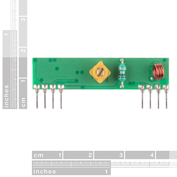
It falls short of the 40mm I measure from end to end with my calipers.
It’s possible my Fritzing doesn’t have the most recent libraries? It says v. 4 but when I just downloaded the latest things from your repository on github that radio wasn’t in it, though it’s listed as sparkfun in fritzing?
For more tutorials on the RF link modules:
http://www.glacialwanderer.com/hobbyrobotics/?p=291
http://letsmakerobots.com/node/12336
http://winavr.scienceprog.com/example-avr-projects/running-tx433-and-rx433-rf-modules-with-avr-microcontrollers.html
http://narobo.com/articles/rfmodules.html
would this work to receive a signal from a garage door opener remote? My new car has a built in remote and I wanted to set up something arduino based for when i get home.
Any ideas on whether this receiver could be suitable to receive 315 MHz signals from tire pressure monitoring system transmitters?
I'm a little concerned it'll be super hard to get good data from this receiver because of everyone's comments about noise ....
It took me a while to get my receiver running. I added a 1M ohm resistor between data and ground, an antenna, and a 330uF cap between ground and vcc then it started receiving reliably.
I have three different circuits built using these devices. One of the three would not receive signals on a consistent basis. After reading a post below where a 1M resistor was add from data out to ground, everything started working great.
Is there a difference between the 315MHz and 434MHz versions of this? (Not in the physical product, but in the range, quality, etc.)
I've used both at 1KHz with no issues. An experiment transmitting from 200 feet away with a couple trees in the way and going around a corner into a window worked pretty well.
Dummy question, do i have to connect all GND pins or connecting 1 pin is enough to power the board?
It will likely work fine with one ground, but for RF parts in particular, the more grounding you can give them the better.
Bought these quite some time ago. Just recently bought a second Arduino to play with, and brought these out to test them. Took some doing (modified the VirtualWire Library) but I finally got them working! I started with the Example code posted here, modified it, and now can turn an LED on and off anywhere in the house. Might not seem like much, but it's a start! Thank you guys for the Example codes and of course the products! Notes: VirtualWire Library needs modification, and powering the transmitter from (my) Arduino Uno's 5v out overloaded the Arduino, using Vin fixed the issue (as I supply 5v 1a through a USB cable/Phone charger) The Duemilanove didn't have this issue.
h
Will these be enough to control my robot platform? all i want is simple forward left right back, or are they specifically for data from sensors?
You could make a simple remote control from these, using a micro or the encoder/decoder chips in the Datasheet.
Has anybody tuned this receiver down to 310MHz for use as an X10 RF remote receiver? Is there a simple process to do this?
Has anyone run into the problem of not being able to receive messages? I set up the transmitter on two different arduino unos. I used the exact sample code for both the transmitter and receiver. I added a check to see if the send function was working, and it did. The receiver, however did not work. Any ideas?
I'm not sure which device to choose between WRL-10533 or WRL-10532. Is there anything to consider besides the frequency?
Hi, I recently bought a transmitter receiver pair of this. I struggled to implement wireless protocol using the AVR tutorial code given, but I failed to even receive even the synchronization byte at the receiver end. I then used Radiotronix 433 Mhz modules which started working at the first instance. I would srongly recommend any one reading this comment not to buy these modules.
WEll, you get what you pay for on this one. I bought two of these receivers and two of 315 transmitters. I wanted to make a short link of about 75 feet. I could not get ANYTHING, no matter what the distance. The output noise is so bad I had to add a software filter to stop my outputs from falsing. Did no good because the link inverts the signal as well. Added an inversion circuit but the noise is so severe nothing will work. It makes no difference how close or far away you are.
Thank goodness I did not spend an arm and a leg to learn this lesson. $30.00 for two bluetooth modules and I now have 115.2k bidirectional as opposed to 2400 one way.
Will never try these again.
I am having trouble getting valid data from this receiver. I'm sending manchester encoded data, all looks good on a 'scope. However the DATA-OUT pin contains a massive amount of digital noise, before, after and superimposed on the data and the PIC uart cant make sense of it.
However I seem to be able to get valid clean data from the RSSI (signal strength) pin. If I hook that up the uart I get valid data, but at a range of only about 10 meters.
I'm using this module with a WRL-08945 (now retired (http://www.sparkfun.com/products/8945)
Anyone have any ideas? Cheers.
Figured it out! :) It's all to do with DC balance and getting to UART to sync properly.
Here's a very helpful document: http://www.radiotronix.com/datasheets/an401.pdf
http://mbed.org/users/4180_1/notebook/ir-and-rf-remote-controls/ has a code example for mbed sending characters from the matching transmitter to the receiver.
Could I send a one-bit (on/off) signal without encoding, virtualWire? Basically, without a uC. I just want an LED to turn on connected to the receiver when a button is pressed on the transmitter. Is this possible?
You can do this, but it would take enough parts to warrant rethinking using a microcontroller on each end (even a very small one like an ATtiny would get the job done).
For the TX side, you'd need a pulse generator (555, etc.) capable of generating two frequencies (one for 1, one for 0).
For the RX side, you'd need a tone decoder that can determine which frequency is being sent, and output the 1 or 0.
They're more expensive (because they do a lot more), but the XBee parts can do virtual wires after a bit of setup.
So I could just send a DC 5V to send a one a 0V to send a 0? I would actually need some modulation? (In that case I'll just load virtualwire on to a tiny85).
Yes, the transmitter needs a constantly-modulated input for the receiver to lock on the the signal.
OK. Thanks! Also... the receiver requires 5V. Any idea on how to (efficiently) get that with batteries? 3xAA is too little, 9V is too big, LiPo is to complex, extra circuity needed. (I want to make a (small) portable transmitter).
A switching converter, which could either boost a lower voltage or buck a higher voltage, will be your most efficient option. We have a number of parts that can do this; take a look at PRT-10255 or PRT-10300 for Lipos, or KIT-10094, DEV-08466, or PRT-08999 for AA/AAAs.
I'll look into those...
Thanks! baum
You get what you pay for holds true for this little gem. Thinking that an xbee would be overkill to transmit a 4 byte message, I decided to try this product. I purchased one of each flavor. Both 315 and 433 Mhz radios produce nothing more than a continous stream of noise that no amount of software, checksums and programming can reliably filter out. I am lucky to get 1 good 4 byte message out of 20 transmits.
I can understand the difficulty. I was able to make it work reliably by using a Manchester-type encoding (guaranteeing sufficient regularity of digital transitions in my serial signal) and adding a pattern to the front-end of each serial packet to give the receiver side software something to lock onto. Close to 100% now. However, I was surprised by the amount of effort required to go from a simple validation (for which I simply used a function generator) to a serial stream containing "intelligent" information. If someone were looking to use this for a very simple control signal, I might suggest a variable frequency output where different frequencies can be interpreted as different commands. That would be very fast and easy to implement with these parts.
"you would need two pairs (of different frequencies) to act as a transmitter/receiver pair."
what does this mean? wouldnt you need 1 receiver and 1 transmitter of the same frequency? I am missing something, can anyone explain this better?
They mean if you want a two-way radio. You would need a 434 transmitter and 315 receiver on one micro; and the 434 receiver and 315 transmitter on the other. Then you wouldn't have interference.
I've got it working with 315MHz Tx/Rx on two separate modules that communicate with each other using the same frequency channel. It was harder than expected. Basically I wrote my own protocol and I turn off the receiver on a module when I transmit from it (power for receiver is from a digital output). If I did not do this it would take the receiver almost a full second to be able to lock onto a return packet. I'm not sure how this device works but it seems like if the adjacent transmitter on a module "yells in its own receiver's ear", then that receiver can't lock onto the faint whisper from a distant transmitter on the same channel for about a second. It's as if the device is somehow self-regulating to lock onto the strongest available signal level. Pretty cool as long as you know what is going on and can deal with it. Using the two separate frequencies would probably be easier. But I will end up with lots of nodes in my wireless system, so I was determined to make it work with a single frequency.
In your example code, you do this:
void loop()
{
char *msg;
if(digitalRead(8) == LOW){
char *msg = "1";
Writing data to an empty, unallocated pointer?!?! Isn't that asking for a segfault?
No, this is completely legal. They set msg to point to a string with one character "1" in it. Later they send this 1-char string via vw_send(). The whole code is not efficient of course, calling strlen() on smth that is always having just one char is just waste of code and CPU, they could've gotten away with a single char variable instead of using a C string. But this is just an example, so as long as it's readable and clear, it's OK,
Does anybody know what the linear output pin is wired for?
The analog output on the receiver module (Received Signal Strength Indicator (RSSI) pin 3) can be connected to an ADC and used as a rough indicator of signal strength whenever the receiver is locked on an RF signal. To be useful, it needs to be read only during signal transmissions. When there is no signal present it will still be a bit high. This is a result of the receivers automatic gain control (AGC) slowly turning up the gain until the digital output starts to toggle from background noise whenever a signal is not present.
See http://davehouston.org/rf-noise.htm
Some designs apparently also use it to disable the receiver output when the signal strength falls below a minimum value.
This is a REALLY mewbie question:
can i have the tx/rx links just transmit a single pulse that will be read by the micro controller...like a HIGH/LOW on a DIO? I don't need serial, i just want to know when a sensor is tripped (or goes to high). Thanks!
The closest you can really get to that would be a slimmed down version of the example code above, which essentially just turns four digital pins on or off. Since these things operate at such a common frequency and don't have any built-in language to handle communication, you kind of have to build it from the ground up. The example code does that pretty well. But without the transmitter constantly pinging the receiver, the receiver just spits out whatever radio noise it can pick up.
You might check out the Wixel (WRL-10665) It's a pricier alternative but it's VERY easy to do what you're talking about with Wixel.
Have a look at the example code for this thing though and see if you can't make it work for you :)
AAhhh!!! Is the transmitter #8945 or #10535???
how can i use this module with arduino.
i want to communicate with home alarm system sensors.
(home alarm system sensors have pt2264 encoder)
related to this, can it differentiate incoming signal id's, to know when a specific 315 MHz signal is sent?
Is there a nice breakout board with USB plug to directly
connect it to a PC (with Linux e.g.)
I've seen a couple of FTDI boards, but they only have 8 pins next
to eachother, not 2x 4 pins like this RF-link board has.
I want an Arduino continuously send data to my Linux PC/server.
Thanks
We don't have a breakout board and probably won't make one. Your best bet would be to just use a small breadboard and connect GND, VCC, TX (or RX, depending on if you're sending or receiving) to an ftdi basic. That's all there is to it.
However, because these pass ALL junk that they receive, it won't be good data. You will probably need to use a microcontroller or software to filter it some how.
Naw, these are receivers (¶1)