- Home
- Product Categories
- Arduino Shields
- SparkFun PWM Shield

SparkFun PWM Shield
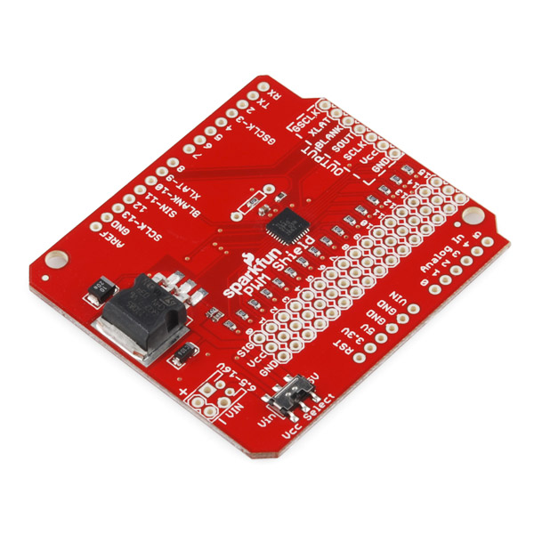
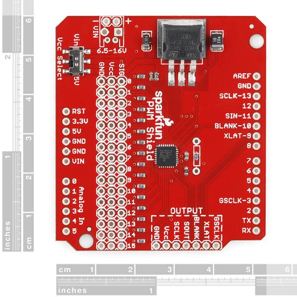
This is the Arduino shield version of our TLC5940 Breakout. The SparkFun PWM Shield will allow you to generate up to 16 PWM signals from your Arduino by utilizing the power of the TLC5940 IC. All 16 PWM channels are broken out to standard 0.1" headers, which run alongside convenient voltage and ground rails. Because the IC can be daisy-chained, output headers are broken out on one side of the shield and can be connected to our TLC5940 Breakout to further expand your PWM capabilities.
Use this board to increase the number of PWM pins available to your microcontroller for applications such as monocolor, multicolor or full-color LED displays, LED signboards, display backlighting, servo control, or any other project where a large number of PWM drivers are necessary.
**Note: **While each 3-pin PWM header is 0.1" spaced, the space between each header is slightly larger in order to accommodate servo connections. In order to make this board suitable for use with servos, 2.2k pull-up resistors have been included on each output as well. Finally, the 2.2k resistor on the Iref pin sets the output current to 17.8mA but a parallel through-hole connection is provided for an additional resistor to increase the current if necessary. To determine the resistor value you need for a given output check the equations provided on the schematic below.
- Schematic
- Eagle Files
- Datasheet (TLC5940)
- GitHub (Design Files & Example Code)
- GitHub (Library)
SparkFun PWM Shield Product Help and Resources
Core Skill: Soldering
This skill defines how difficult the soldering is on a particular product. It might be a couple simple solder joints, or require special reflow tools.
Skill Level: Rookie - The number of pins increases, and you will have to determine polarity of components and some of the components might be a bit trickier or close together. You might need solder wick or flux.
See all skill levels
Core Skill: Programming
If a board needs code or communicates somehow, you're going to need to know how to program or interface with it. The programming skill is all about communication and code.
Skill Level: Rookie - You will need a better fundamental understand of what code is, and how it works. You will be using beginner-level software and development tools like Arduino. You will be dealing directly with code, but numerous examples and libraries are available. Sensors or shields will communicate with serial or TTL.
See all skill levels
Core Skill: Electrical Prototyping
If it requires power, you need to know how much, what all the pins do, and how to hook it up. You may need to reference datasheets, schematics, and know the ins and outs of electronics.
Skill Level: Rookie - You may be required to know a bit more about the component, such as orientation, or how to hook it up, in addition to power requirements. You will need to understand polarized components.
See all skill levels
Comments
Looking for answers to technical questions?
We welcome your comments and suggestions below. However, if you are looking for solutions to technical questions please see our Technical Assistance page.
Customer Reviews
4 out of 5
Based on 2 ratings:
Works fine
Does the job. I hooked up 5 rgb led (using 15 of 16 channels) and was able to use the library to control them. I made my own class to allow controlling them by HSV values, then use the update method to send the resulting RGB values to my leds. Works fine.
Fair rating
I am having some trouble figuring out the library and how to write PWM and other functions on the board. Library examples are not very clear. Have not gotten it to work yet. Soldering was a hassle.
I've been using this board with my Arduino for a couple of years now and am generally happy with it. I added in a few breakout boards now too. I have the outputs connected to relays (both mechanical and SSR) running some light strings (LED and incandescent). But all along I have had an issue with it. I occasionally get a "flash" from most of the channels, meaning that all of the channels light up for a brief instant. This occurred when using the single board without the breakout boards. I am using the Rugged Audio Shield and another shield holding a micro SD card. I tried checking if I was sending a command to the shield to turn on all the lights, but nope. I also did a get at each step to see if something was getting set, but nothing showed up there. Still some more work I plan to do to try to figure out what is going on, but am hoping that someone might have some thoughts.
Can I drive MOSFETs with this board? Building a solar air panels need to drive the fans(12-24 VDC). Thanks
Does this shield have a total current limitation? Can it be used with an external power supply? I'd like to be able to use >1A at the same time or more (120 mA per PWM channel x 12 channels). Sorry if this is answered somewhere in the manuals. I'm quite new to electronics. Thanks for the advice!
Can you recommend a header to allow servos to be plugged into the module?
If your servo has a female connector coming off of it (like most do), you'll want straight male headers. That comes as a strip of 40 headers, which you can break into multiple sets of 3's.
Could you break off 3 sets of 16, or is the spacing wrong for that?
Hello all, I want to ask about this module, what is the maximum frequency of this pwm module can transfer? is it able to deliver max 500Hz? thank you very much.
I am trying to use this shield to control some some relay boards to control some 120v LED Christmas lights. This board is hooked up to the SainSmart 8-Channel 5V Solid State Relay Module Board and also SainSmart 8-Channel 5V Relay Module. I can't get the lights to fade. It appears that I am getting some PWM going as the LED's on the relay boards are acting as I expect. But the 120v Christmas light LED strings blink instead of fading. Any ideas? I believe that it is a zero crossing issue, but not sure how to fix it. Not sure if the relay module could support this as they are physical relays. But the SSR is advertised as supporting zero crossing. Thanks
Can I use this with a Raspberry Pi? And if so, does anyone have some example code and/or tutorial for hooking it up to the RPi?
I was disappointed to see that this controller doesn't have a "slave select" line for using multiple controllers together. They can be daisy-chained (forming a larger shift register) but there's no built-in provision for having multiple controllers sharing the serial bus with other SPI stuff, or with other controllers in a non-linear topology... Otherwise it looks pretty cool. I guess I could share the serial line by gating the clock... Eh... Also, are those pull-ups on the outputs necessary? I couldn't find anything in the datasheet about it...
This board is designed around constant current LEDs to act as a sink. However, using the 5 volt pullups allows you to use this board with motors, etc.
Has anyone used Serial Communication with PWM Shield? If I use tlc.update() Serial communication stops. Thanks in advance
I have servo(s06nf) that make my arduino uno reset sometime because it appear to be using to much current. Can I drive such servo with this board provided i source an external power source(7.2 v) ?
I noticed that this board has a place on it for screw terminals for power. It shows "6.5-16V" in the pictures above. Does anyone know which size screw terminals fits it? Do either of the ones below fit?
http://www.sparkfun.com/products/10571
http://www.sparkfun.com/products/8432
Thanks in advance!
Heh, you found the two screw terminals that won't fit :). This 3.5mm one will work though: http://www.sparkfun.com/products/8084.
Has anyone successfully used this shield in combination with the official ethernet shield?
I'm also a little confused on the exact way I should wire this up, I need to control around 14 channels of LED light strips, each one draws about 500ma@12V.
The strips will have a common anode tied directly to +12V regulated power supply, with the cathode of each strip tied to the drain of an IRF510 mosfet...
I successfully tested a single strip by tieing a digital output to the irf510 gate(130ohm resister to arduino, 10k resistor to ground) and the irf510 source connected to ground.
By my logic, all I believe is necessary is to move the connection from my digital pin, to the signal pin for a channel...
If anyone knows much about this, I would appreciate either confirmation that my logic is not flawed, or a smack on the hand before I hook it all up and fry something...
I bought this shield. I want to control 16 servos.
my servos is... http://www.hobbyking.com/hobbyking/store/__4160__Pico_F_BB_Servo_w_JR_Plug_6_2g_10sec_9kg.html
three servos moves. but many servos dosn't move.
I use arduino in 5v.
Do I need out vcc power ? and some resistance ??
if I try to use the AC adptor(12V / 1A). if Does I need how the resistance?
Please I want to these advices from you.
best
I'm guessing that the selector switch on this board does not like excessive current. I have 15 servos connected to it, I made a 90 degree offset mistake in my program which caused all 15 to stall simultaneously on my robot and next thing smoke pours out of the switch and it all stops.
I have: 8 HS-645MG - Stall current of 450mA ea. 3 HS-488HB - Stall current of 180mA ea. 4 HS-422HB - Stall current of 180mA ea.
Total stall current of 4860mA, I'm guessing the switch is rated around 1A. lol
Any suggestions of what I should do instead?
Yeah I bought a second one because of an issue like this. I tried changing the switch voltage to 7v for the servo pins by removing the switch and putting a voltage regulator in its place.
The second one I took extra precaution to try and isolate the voltage, I reinforced the power and ground lines on the servo pins... But... I accidentally left the voltage switch in tact which likely caused a problem. This time, I kept it to 5v... but I smelled a little smoke.
After poking around a bit, I realized the pull up resistors. Which means the chip is grounding the signal lines to produce it's servo signal. I'm not sure if this is good for heavier duty servos or not. I'm not sure how much current the "SIGNAL" line draws for a servo...
I'm weary about ordering a third just to bust it too... I'm thinking about just making one that kinda does what I was trying to do, but just uses the arduino's Digital IO lines instead...
I need to drive 12+ servos now. Mine are higher current as well. I tried the pololu, but the examples really sucked and it only does 8.
Any bright ideas?
Yeah, I just unsoldered the switch and replaced it with a piece of wire. I will let you know if the traces survive the maximum current of 4.8A.
I'm sure that the 5V regulator will not like 4.8A being drawn, besides I have a Programmable BEC that can source up 20A @ 6.0V. If I melt the traces I'm soldering a thick piece of wire over all the VCC and GND pins and connecting them to the BEC directly. As for the servo signal, it shouldn’t take “any current” as far as I’m aware their circuitry is CMOS based. It has to be if the idle current is rated to be 8.8mA.
Sparkfun should put a selector jumper instead of a flimsy switch ;)
Does this shield work with the chipkit UNO32 ?
Does anyone know what the Max current is for the PWM?
I have great performance with 2 "big" servos, but when I add a third servo they start acting really funny... I've tested two servo's on many pins, so it's not a signal issue.
The only thing I can think it might be is the Current. I'm driving some: http://servocity.com/html/hs-7980th_servo.html Servos... Unfortunately they are not updated with current requirements. Though I would expect them to be similar to: http://servocity.com/html/hsr-5990tg_servo.html servos at around 360mA each.
Any ideas about the limitations here? I'm running the source through the Ethernet Arduino.
The next thing to try would be to reinforce the traces on the power rail for the servo's and then plug the servo rail in directly to the source with my voltage regulator.
Any Thoughts??
How do you power your servos? The Arduino can only give you up to 500mA...
It appears that the breakout holes are not 0.100" apart. Does anyone know how far apart they are and WHY? I'd love to source a header for it and I just found out that the one I ordered doesn't fit.
Funny enough, the rows are 0.1" apart. But the columns are still some odd length. This is going to be ugly if I want this board to be reusable. I highly suggest anyone interested in this shield to get themselves a ProtoBoard and the TLC5940 DIP instead. Much easier to work with.
The reasoning behind this is to accommodate servo connectors. Some connectors are too big to fit if the rows are .1" spaced, so we padded them a bit to allow for the board to be fully populated with servo connectors if need be.
you forgot to mention that all the PWMs are 12-bit, or 4,096 steps instead of the normal Arduino's 8-bit or 256 steps.
HMMMM. It's worth noting that the signal you get from using this with the Arduino library might not be what you expect. As a constant current sink, this chip will generate a LOWER duty cycle as the value is increased in the code. Applying a value of 4096 will turn it into ESSENTIALLY an open drain. Sending 1 will make it have almost a 100% duty cycle. This can be addressed in code easily by mapping 0,4096,4096,0 etc, but should be remembered. You can also throw a hex inverter in between this unit and your target if you're looking to JUST generate pulses and constant current is unimportant.
OMG, I have been going crazy with this.
I have a project where I am using the signal pin to drive the gate of a MOSFET and calling the Tls.clearAll(), turns everything on. And setting the values to chanel values to 4095 turns it off.... I was sure I had connected something up incorrectly. Thank you for this bit if information.
I was seeing one other thing values in the middle of the 0-4095 range were getting stronger then weaker then stronger again, it was not appearing to produce an ever increasing PWM signal. I will do some more testing and post back here when I know more.
This can be addressed in code easily by mapping 0,4096,4096,0 etc
That surprised the heck out of me, I thought I did something wrong. A better fix may just be 4095 - value. I'm not sure how intensive mapping is. Isn't this a big issue? calling clear sets everything wide open?
The issue is that the output will never be fully "off" in this instance. A version using a hex inverter to properly invert the signal would be very useful. I'm working on a high power LED project using external drivers, and having this all nicely packaged up would be delightful.