- Home
- Solid State Relay - 8A

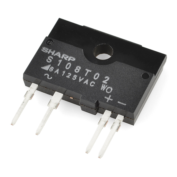
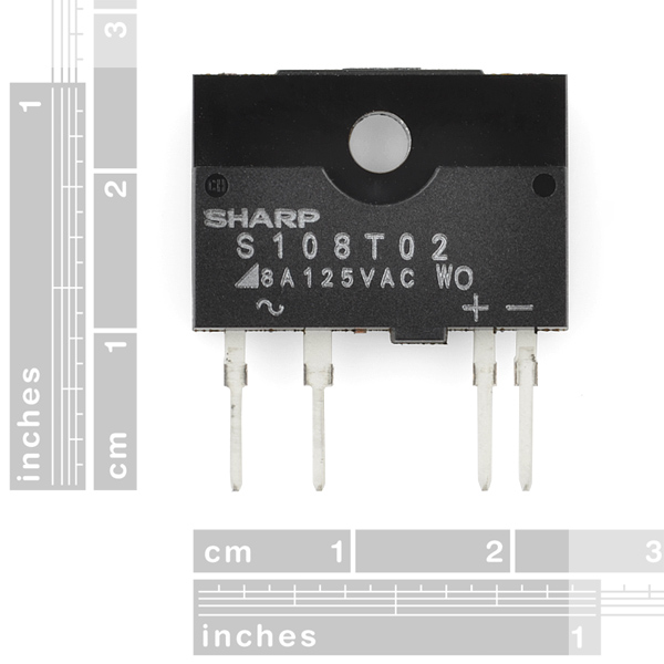
Solid State Relay - 8A
A solid state relay (SSR) is just what it sounds like; an IC that acts like a mechanical relay. They allow you to control high-voltage AC loads from lower voltage DC control circuitry. Solid state relays, have several advantages over mechanical relays. One such advantage is that they can be switched by a much lower voltage and at a much lower current than most mechanical relays. Also, because there's no moving contacts, solid state relays can be switched much faster and for much longer periods without wearing out.
They accomplish this by using infrared light as the 'contact,' a solid-state relay is really just an IR LED and a phototriac sealed up into a little box. Thanks to the fact that the two sides of the relay are photo-coupled, you can rely on the same type of electrical isolation as in mechanical relays. These particular solid state relays can switch 400VAC and 8A.
Solid State Relay - 8A Product Help and Resources
Adding a Timed Button to a Project
July 29, 2015
This tutorial will walk you through making a timed power controller for interactive projects. You will learn how to add an on button that will provide power to your project for an amount of time and then turn off again.
Core Skill: Electrical Prototyping
If it requires power, you need to know how much, what all the pins do, and how to hook it up. You may need to reference datasheets, schematics, and know the ins and outs of electronics.
Skill Level: Competent - You will be required to reference a datasheet or schematic to know how to use a component. Your knowledge of a datasheet will only require basic features like power requirements, pinouts, or communications type. Also, you may need a power supply that?s greater than 12V or more than 1A worth of current.
See all skill levels
Comments
Looking for answers to technical questions?
We welcome your comments and suggestions below. However, if you are looking for solutions to technical questions please see our Technical Assistance page.
Customer Reviews
4.1 out of 5
Based on 9 ratings:
3 of 3 found this helpful:
Great device but - RTFM - only works for AC loads.
It is very easy to integrate this into a project since Sparkfun provides the EAGLE footprint and sample circuits. I was able to add an AC switching element to my board very quickly. Initially, I was wondering why it was AC only and then I realized that when you switch off the relay, it is only changed once the load passes through zero volts and goes negative. As a DC load does no such thing, this device can switch it on - but not off.
The device is functions as expected and it is clearly marked for AC loads by Sparkfun so this is just me pointing to the obvious.
1 of 1 found this helpful:
Very usable.
Used this in my very first Arduino project and was quite satisfied. Using it to switch 150 watt resistive load - rather tame for the 8 amp rating so there is no heating issue.
Works well, but keep a few things in mind...
This relay is a huge upgrade over the mechanical relays you might be used to (no clicking, much more reliable). However, keep in mind a few things..
1) The internal switching mechanism is an IR LED, so don't forget a current-limiting resistor in your design! (I'm glad I bought two, because I fried my first one.. facepalm.)
2) While the current rating is 8A, you'll need a heatsink to operate this high. Without a heat sink, you shouldn't operate at >2.5A at room temperature. Be sure to check out the datasheet (p.6 Fig.2) for more info.
Using a trinket to control a 175w street light
I'm using a tiny arduino to turn a street light on and off using a Cadmium Sulfide Cell. I'm using this relay to switch the 120v power to the mercury vapor street light. When the light comes on it pulls several amps as the arc starts, then the current demand decreases to about 1.5 amps. This switch has worked perfectly for two weeks. I just purchased 3 more just to hold in case I have another use for them. It cycles on/off once a day and stays on for about 10 hours.
Part works well, Eagle library silkscreen needs work
I bought this part as an easy way to control some grow lights remotely (no I don't live in CO, so not that kind of growing). I assembled this on a custom designed PCB with the relay, some heavy duty terminal blocks and pinouts for a TMP102 temp sensor, all this controlled by a Particle Photon. Overall the project works well, though having a heatsink is mandatory for any loads over maybe 0.5A, anything after that it gets uncomfortably warm (and decreases it's lifetime), at my demand of 160W(1.33A) things get hot enough to make me uncomfortable, the data sheet tells you this same story but you have to read carefully to understand the devices limits, if you try to pull 8A you will need some serious heatsinking or you'll let the magic smoke out, nothing to mess around with when working with 120VAC.
The one real bummer was me connecting the control lines to the holes spaced for the AC input on the first revision of the PCB (a very well learned $30 mistake), I should have probably noticed it, but their are no markings in the SF Eagle library for this part, it just shows the outline, so you have to go by the hole spacing, subtle if you aren't expecting it. Be mindful in your design process and this is a great buy, just don't expect mechanical relay power performance without some serious effort on your part.
very nice
This is the smallest sold state relay I found and it is very nice and easy to install..
Great small footprint relay
I lost both due to error in circuit. Used my one spare to check circuit changes and works great. Sorry I can't buy more to finish project as out of stock with no date expected to be available
Sorry, this one is being retired. :(
Anyone know of a good alternative to one of these. I've been working on a project with 3 of these and I just accidentally broke the lead on one trying to re-solder it.
It's worth noting it's 400V peak, not RMS. If you're living in the 230V part of the world, you should definitely go for a 600V version (S208T02, S202S02F). 400V peak is only ~280V RMS which leaves a quite low safety margin for continuous usage under 230V. By the way, these are listed as obsolete by Digi-Key - they list the S202S02F instead. Just saying.
To the guys looking for a way to make a light dimmer: you won't make a proper dimmer by just getting a non-zero-crossing version of this one here - you'll have to drive it with a zero-crossing sensing circuit. Google the U2008 IC instead. It's a cool phase-control IC. It's not as "plug-and-play" as this one here as it requires some external circuitry like the optocoupler on the input and an external power triac to trigger (it doesn't carry the current by itself). But with proper few external elements you can control your mains load with a PWM output - how cool is that! Maybe there is some completely integrated solution like this one here. Somewhere. But I'm not aware of that.
A a footnote, Sparkfun should pay a little more attention to the customers from 230V parts of the world. You ship globally and have customers all around the world (me included) so the information on the mains voltage should scream at you in bold red font in the relevant product descriptions. Not like in case of soldering stations you carry, where the voltage info is just barely mentioned somewhere within the description. These days, when surfing for stuff, sometimes you don't even bother to check where in the world the seller is located and OTOH you sometimes tend to take the "right" voltage for granted so it's really important for you to pay a little more attention to that.
I don't know where you get your math from, but it's definitely not the same one the rest of the world uses. Let's say I have 230V rms, the peak voltage is 230 multiplied by the square root of 2, which is approximately 1.414. So 230 * 1.414 is between 325 and 326 volts, well within the range of this solid state relay (with almost 75V safety margin...)
So from https://en.wikipedia.org/wiki/Root_mean_square A similar analysis leads to the analogous equation for sinusoidal voltage:
Where IP represents the peak current and VP represents the peak voltage.
Because of their usefulness in carrying out power calculations, listed voltages for power outlets, e.g. 120 V (USA) or 230 V (Europe), are almost always quoted in RMS values, and not peak values. Peak values can be calculated from RMS values from the above formula, which implies Vp = VRMS × √2, assuming the source is a pure sine wave. Thus the peak value of the mains voltage in the USA is about 120 × √2, or about 170 volts. The peak-to-peak voltage, being twice this, is about 340 volts. A similar calculation indicates that the peak-to-peak mains voltage in Europe is about 650 volts."
So these are not good for 240 Volts like we have in Australia as the peak to peak voltage can be 650 Volts
Will you comment then on who or what is right for RMS 240 Volts ?
I might add 240 Volts times square root of 2 equals 340 volts but the peak to peak is twice that or 679 Volts --80 volts over the rating?
A couple of comments to help people use these:
a) As others have said, because it's a triac-based device, it can not be used on a DC load. AC load only!
(You can also get MOSFET-based easy to use "solid-state relay" devices for DC use.)
b) The input side is basically just a LED. Forward voltage drop is 1.2 V at 20 mA. (It's an IR LED.) So, basically, if you've got an Arduino or whatever, you just drive it like it's a LED. You hook the cathode up to ground, and hook the anode up to an Arduino output with a resistor in series - about 220 R or 330 R or so, maybe 470 R or 1 k if that's all you've got laying around. And it works!
c) If you're wiring up 120 V or 240 V AC line voltage, remember to be careful and sensible and stay safe.
I should have read this earlier concerning hooking it up like an LED, now I burned up 2 relays without knowing why...
Can these be used in parallel to increase the maximum current allowed?
Relay noob here,
1) On page 9 of the datasheet (showing the standard circuit), a protection diode is on the DC controller side. Why is this necessary? Is not the optical isolation sufficient protection?
2) Any decent tutorials on snubber circuits?
3) How do I figure the required size of heatsink? On pg6, fig2, do I read up my ambient temp to the desired A, then find the closest curve above it? Do these "Al plates" described need cooling fins, or is just a smooth lunk of metal sufficient?
I'm also curious about that diode. Why is that in the sample circuit?
It is there most likely in cases where the relay is being triggered by a microcontroller, as when the microcontrollers effectively turn "off" a load, they actually send signal 0 which to the microncontroller is ground - 0 v. So it simply reverses polarity in the 5V circuit, this could cause damage to the solid state relay, so the diode prevents this from being a problem since current can only flow in the correct direction with the diode in place.
A decent solid start relay for sale? You just made my day Sparkfun! I always have a huge amount of trouble finding SSRs. Just wish I knew what kind of amperage it could take at 120 volts.
Could this be used to switch 100vdc at 300khz with a 10% duty cycle?
THIS PART CANNOT SWITCH DC LOADS. Please put this in the description so I don't have to study so hard! thanks,
Here's some that switch DC loads called 'optomos', gotta love that description...
180ma DC - http://www.digikey.com/product-detail/en/CPC1981Y/CLA203-ND/700422
2.5 amps DC - http://www.digikey.com/product-detail/en/CPC1916Y/CLA209-ND/654909
.... as noted below you can just design a mosfet circuit for these smallish loads but if you really need isolation here you go.
Can I use it from raspberrypi (3.3v) to drive a DC circuit at 12v? If yes, how? Do I need transistor?
Hello all, I am designing a light show to be powered based upon a bendable force sensor sending me and int 0-1024 based on how much the sensor is bending. I will be using this value, and map its variation to a 0-255 range so that i can use it to power a relay to control a 120 volt circuit. Can anyone send me a circuit diagram and information about what sort of relay I should be using. I was thinking a non mechanical one would be better because I am going to be switching the circuit on and off pretty fast to get a duty cycle going on the 120 volt circuit. I just don't know if there is a transistor capable of switching a 120 volt load with a 5 vault switch. The force sensor is going to measure air coming out of a sub woofer. Anyone who thinks it would be better to do this using the audio signal itself, I have no clue where to begin with that so I am just going to do it this way.
Hi, as stated in the datasheet, it mentioned it has high isolation voltage between input and output. Does that mean it is well isolated so I don't have to set up a protection for my raspberry pi when I connecting them together ( in case of damaging my raspi) ?
They make Automotive and other DC switched versions of these devices. It'd be nice to have something in this class of device that did this available (And I'm a bit surprised with the emphasis on robotics SparkFun has that they don't carry such parts in inventory...) Guess I'll be looking elsewhere for that because I need it for a project and I need to be switching about 4-5A at 12V on an often enough basis that I'm needing to worry about contact life on a electromechanical relay.
When these are used with higher power devices, a heat sink is recommended. The hole size on the TO-220 sink (https://www.sparkfun.com/products/121) looks compatible. Are there any problems using those, that I'm not seeing?
Sharp has changed the package for this device, and this particular version Sparkfun is selling is the older, prior design. The new form factor (P/N S202S02F) fits a TO-220 heat sink perfectly, whereas this older design not as well. Same specs otherwise. I use these with no heat sink for loads under 2 amps. Work great. If you want to make your own "marginal" heat sink, cut a small piece of extruded aluminum angle or C-bar and adhere it on. IMO don't go 8 amps with these, stay below 5 amps (use a heat sink above 2 amps).
And if you're adhering, make SURE it's a thermal adhesive like Artic Alumina.
Hey, I was thinking of starting a Christmas project in which several light strands are timed to music. At one point I would like them to blink very fast; is there any danger to switching on and off 120V AC at high speeds (like 10 times per second)? Thanks.
This particular model only turns on during the times when the AC voltage is at 0 v, which is twice per cycle, or 120 times a second. Commanding the device on and off 10 times a second is not a problem at all.
Hello, question: The datasheet says that the minimum trigger current, under this conditions VD=6V, RL=30Ω, is 8 mA, i'm a chemical engineer and i don't know much about electronic circuits, so help-me out here.... i'm assuming the RL is the resistor shown on pg 9 connected to the VCC. is this correct? Can i use one lipo (3.7V) as power supply? if so, how can i calculate the RL?
Thank you guys!
RL usually refers to the load, i.e. what you are powering on the A/C side. I'm not sure if that is the case here. But a 3.7V power supply should be plenty. To calculate the value for the resistor connected to Vcc (R1 in the diagram), use V=IR. Datasheet says typical voltage to turn the relay on is 1.2V, and current is 20mA. The purpose of the resistor is to set this current at around 20mA. If supply voltage is 3.7V and the relay needs 1.2V input, the voltage across the resistor should be 2.5V. 2.5V / 20mA gives a resistor value of 125ohms. I don't think resistors come in 125ohms, but 120ohm or 130ohm should work just fine.
Use as said above like an LED on the DC side . Thats what it is!
I would also love a DC version, I do fun stuff with the Rebel LEDs. The Rebel LEDs are something that must be witnessed in person to understand how bright they are, a photo doesn't do them justice.
Ah, someone else looking for what I was.
What you're looking for is an N-Channel Logic Level Power Mosfet.
Connect it between your LED and ground, and send logic level high to the gate and voila, your led turns on.
Keep in mind though, that LED's require a constant current power source, so if your LED(s) didn't come with a driver, you'll need a way to limit current else they'll burn themselves out.
Anyone ever used these to switch 24vac HVAC lines in a thermostat?
The data sheet says the minumum "load supply voltage' is 80V. It also says the maximum zero crossing voltage is 35V, so at 24V it may not "see" the sero crossing and never turn on.
I am running a fan with one at 230V 1.7A (>10A for very few milliseconds during startup). It doesn't get noticeably warm when used 2-3 times per hour for 2 minutes on each time. During the summer it could be on for 8-10 straight hours. Is that an acceptable use for this thing, or should I use a relay?
Using these with a MSGEQ7 to drive christmas lights and I'm pleasantly surprised at how well they work. Don't even get warm with 100 bulb strands. I'm probably still comparing it to the HSR412s I've melted though. Teehee.
Any idea what the leakage current of the triac is? Since it is not a physically "open" switch, some current must leak, right?
Thanks for the example layout. On the top copper layer, the switch current is run through a couple pours, which is good, but then the pin connections are isolated with thermals. That would, it seems to me, "neck down" the effective copper width to carry the current to something like 80 mil (only two spokes per pour, per side connect to the pins on the relay). That's barely enough to carry 8A with 2.5oz copper. Removing the thermals, or increasing the size of the pour to get 4 spokes per side would be a good idea.
See images
I'm just throwing in a vote for carrying a DC SSR as well. This is a great one at a great price, btw, so thank you!!!
DC SSR is essentially just a MOSFET... Google 'MOSFET as a switch'.
And, to the point I am making...
http://www.opto22.com/site/pr_details.aspx?cid=4&item=DC60S5
If you follow up the link, this is the class of device I'm referring to (And needing- yes, I'm trying to switch that much current...7 times over...). "Just a MOSFET" doesn't get you isolation combined with fairly high switch currents without a lot of thought and design that people like Cydom or Opto-22 put into making these things. One could use a motor controller, but it's not really designed for switching there, they are designed to control brushed or brushless motors which is a differing beastie than a "relay" is.
Yes, that it is, but you have to design up the circuit, etc. They make these nifty packaged up devices that don't need a circuitboard, trying to figure out the resistances needed, etc. and handle quite a bit of amperage.
Just because it's essentially just a MOSFET, doesn't mean someone wants to mess with that aspect of things- sometimes they just want a solid-state switch for a design. Yes, I know, lazy. I'll own that in this case- but I've bigger fish to fry and have limited resources (time being one of them...) on a project of moderate import to a lot more than just myself. They package them up for people for just this reason and it'd be nice to be able to have a one-stop shop for this stuff.
(Hint: This device is little more than an LED and photo TRIAC and can easily be done that way- but you see it in a similar convienient package...)
Anyone have an Eagle library for this yet?
Check the example layout we linked to. You can export the part and footprint using the standard eagle ULP.
Note to anyone wanting to use this. Because it uses a TRAIC for the switch, it can not be used to control DC current.
THESE CANNOT switch 8 Amps without a VERY large heatsink! 20x20cm! Read the derating curves on page 6 of the datasheet or you will let the smoke out. We've done it before at work.
I want to know when SparkFun will start carying the infinite heatsink mentioned in figure 2 of the datasheet. Just think of the possibilities.
Just use a large sheet of aluminum.
I would have loved to use one of these for an AC light dimmer, but alas, it is not meant to be.
If these start selling pretty well, would there be any chance of stocking the version without the zero cross detector?
I'll second that! first thing I looked for was if the device would wait to switch at zero crossing. Really helps with noise problems that way. please stock the device version that has the zero crossing detector.
This S108T02 is the zero crossing version ... the S108T01 is the non zero crossing version.
Am I reading the datasheet right, it takes 1.4V to switch the load?
It almost looks like a bridge rectifier offhand :) what with the pin labels. More importantly though, the datasheet does not specify whether the switched voltage is ac or dc. the tilde on the ic package labels it for ac, but what would the dc limits be, if it will even accept dc?
I thought the same thing when I saw the pic. The data sheet says the minimum load frequency is 47Hz so I assume it is AC only, but I wonder if it would switch a smaller DC load. (2 Amp?)
As the switching element is a triac (two thyristors back to back) it would only be able to turn on a DC load, not turn it off.
Worse than that, since the triggering element is zero crossing, it would not switch on until ... power is removed !
Reminds me of the write only memory or the batteryless solar lamp !
Need a breakout board like the Relay Control PCB.
Why do you need one? It's not like an EM relay that you need diodes and such... you only need a transistor. Are you actually going to pay for a PCB that has this SSR, a transistor, and maybe screw terminals for the output? Make it on a mini breadboard!
I had thought about this. This SSR is nicely 0.1" spaced and very breadboard compatible. But when I'm dealing with 110VAC, don't think a breadboard would be capable of handling a lot of power. I don't want main voltage anywhere near the rest of circuit or my body. I don't want connections shaking lose. I really like the idea of a PCB that is solid and stable.
Agreed! We'll start spinning them today, available soon.