- Home
- Product Categories
- Current
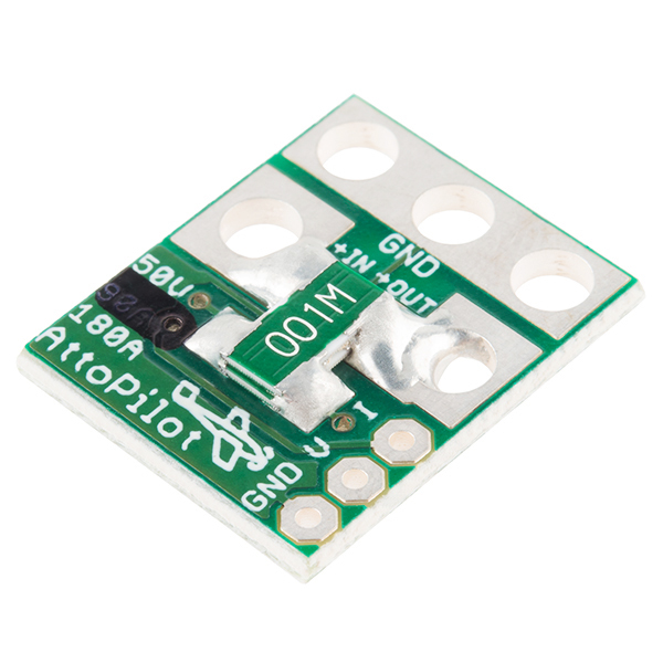
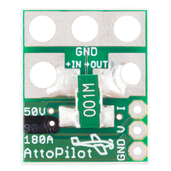
- AttoPilot Voltage and Current Sense Breakout - 180A

AttoPilot Voltage and Current Sense Breakout - 180A
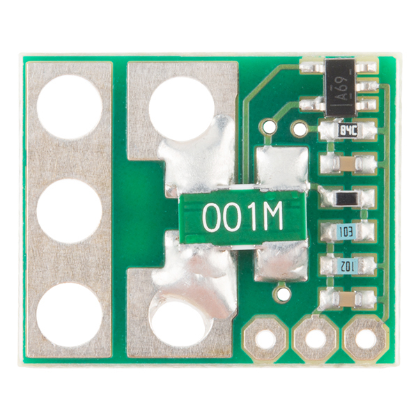
This is a small voltage and current sense PCB. DC current is determined by measuring a voltage drop across a pair of parallel shunt resistors, then converted to a final analog voltage output by the TI INA-169. Voltage sense is accomplished by scaling to 3.3V ADC range by a precision resistor divider.
The PCB is supplied without leads or connectors. The pad sizes are large enough to accommodate 12 gauge heavy duty leads (see datasheet) but care must be exercised in soldering. Smaller gauge leads are considerably easier to solder without creating shorts.
- 51.8V Max
- 178.8A Max
- Very low zero current offset
- Analog output scaled for 3.3V ADC
- Self Powered
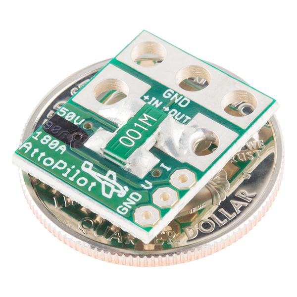
- 4 x 15 x 19mm
- [Datasheet](http://cdn.sparkfun.com/datasheets/Sensors/Current/DC Voltage and Current Sense PCB with Analog Output.pdf)
- Example Sketch
AttoPilot Voltage and Current Sense Breakout - 180A Product Help and Resources
Core Skill: Soldering
This skill defines how difficult the soldering is on a particular product. It might be a couple simple solder joints, or require special reflow tools.
Skill Level: Noob - Some basic soldering is required, but it is limited to a just a few pins, basic through-hole soldering, and couple (if any) polarized components. A basic soldering iron is all you should need.
See all skill levels
Core Skill: Electrical Prototyping
If it requires power, you need to know how much, what all the pins do, and how to hook it up. You may need to reference datasheets, schematics, and know the ins and outs of electronics.
Skill Level: Competent - You will be required to reference a datasheet or schematic to know how to use a component. Your knowledge of a datasheet will only require basic features like power requirements, pinouts, or communications type. Also, you may need a power supply that?s greater than 12V or more than 1A worth of current.
See all skill levels
Comments
Looking for answers to technical questions?
We welcome your comments and suggestions below. However, if you are looking for solutions to technical questions please see our Technical Assistance page.
Customer Reviews
4.1 out of 5
Based on 18 ratings:
1 of 1 found this helpful:
Works as advertized
It was easy to assemble and is doing it job without any complaints.
1 of 1 found this helpful:
work perfect
work perfect with pixhawk. thx
1 of 1 found this helpful:
so far so good
works really well with APM 2.6 and mission planner. they have pre populated setups for the atto's and it worked exactly as it said, the first time with no screwing around with it. really happy now I can use it on my 6s multi rotors
1 of 1 found this helpful:
It's All Good
Using this with an original 3DR Pixhawk and ArduCopter 3.4 on an 800mm hexacopter with SunnySky 580kv motors and 4S LiPo and it just works. Once it's wired in you just select the AttoPilot 180 from ArduPilot drop-down list. Recommended.
1 of 1 found this helpful:
was good when arrived
The signal outputs is very close to power connectors. I prefer them to be on the side. Do not solder and re solder again because the pcb material can easily be damaged. Overall it was ok. altought I burned it and have to buy anaother one.. :)
1 of 1 found this helpful:
Works Just Like It's Suppose to
I connected this up and it was simple and works great. Only draw back is pixhawk won't register a current draw u Der 3 amps but once the motors are running it's right on. I will advise instead of soldering the 3 sensors wires to this current sensor you should spend $2 on a pin header. Straight or angled pins. Then you can plug a 3 wire servo plug right onto it. 3dr sells 15 pin df13 connectors with servo plugs on the other end. Like the telemetry cable for apm. Well you can pull the pins out of that plug, insert 3 of them into the plastic plug for pixhawks power and the the other end each connector will slide right into a servo plug. That's what I did and I was able to make the cable with a servo ug on one end for plugging onto the pin header I installed on this sensor and the other end had the df13 plug pixhawk uses with the other end of those 3 wires. So no soldering or anything.. to make the cable you just need a apm telemtry\osd cable and the. Pop the pins out of the plugs and reinsert them into a servo plug on 1 end and pixhawks power plug on the other.. that made installing this sensor a piece of cake..
1 of 1 found this helpful:
Using it with Pixhawk on 6s setup
A little tricky to solder 8 AWG wires to the small board
41 días y sin recibir
lo necesito urgente y esto no llega nunca
Hi, this sounds more like a shipping related question than a review of the product. I recommend contacting our customer service at customerservice@sparkfun.com if you have further questions about your order.
Dead on arrival =(
The current output pin is always at 0.00V. Voltage pin works ok. I tested it with both the autopilot telemetry and a multimeter. The autopilot works ok but no matter how much current I input, it always displays CERO volts. I checked for possible false contacts but it looks and works ok (tested each pin for continuity with multimeter). I guess this one is faulty...
Sorry to hear you're having issues with this breakout. If you contact our tech support team, they can help you resolve them.
0 of 1 found this helpful:
It works
With a market that has a surprising low support for 6s and up batteries, or higher current applications, this definitely fits the bill. Nothing else like it. Im not sure that its extremely accurate, as when i went to calibrate it, the default settings(ardupilot) were off ( i could only calibrate it at 10 amps, but the sensor was reading half of what it should with default ardupilot settings). Mah counting and battery charging seem pretty close though so its not far off once calibrated. The voltage reading was spot on.
My setup was seeing bursts of 160+ amps.
I would buy this again.
Excellent quality fast delivery.
I received in 2 days in a great package. Quality is great.
I never received the article
I never received the article and I have no way of investigating what happened. Bad thing.
I'm sorry to hear that! Get in touch with our customer service team at customerservice@sparkfun.com and they can help you with your order.
Good product but overpriced
Wow, they must be making a pretty big margin at this price. Otherwise it is a solid board with accurate readings.
not as what is pictured
Item works fantastic, but seems to be older version without the cutouts for deans connector. I order two and these do not have cutout for deans connector. So I went back to website and ordered two more based on image showing cutouts for deans plug, but when items arrived these were the previous boards with no cutouts for deans. I now have four of the boards with no cutouts. Please revise your image or stock of these items.
Hi, So sorry for this issue. These actually appear to be the new version. All units appear to no longer include a deans connection cutout like you mentioned. We will absolutely update our photos to reflect this change. Thank you
ATTO180
An excellent electrical design and rugged. excellent value versus performance.
GOOD ITEM
IT WORK VERY WELL THANK YOU
Unit #4
We have modified all our quad and hex copters to 6s lipo. These units are rock solid and easy to integrate.
Have these been discontinued? I can't find them anywhere.
Our application can go up to 56V (when battery is fully charged), will this work?
Thanks.
dmgoedde or anyone can you please help me with the Atto180A ground.
What is the correct way to connect the AttoPilot 180A ground wire without causing a ground loop when using two separately fed 6Ss into a PDB while only sensing one of the packs (I only want to monitor 1 pack)? Pixhawk is powered via the top power port using the original Pixhawk PM via a separate 3S (I’m not running the Pixhawk from the PDB).
I have hit a massive dead end after trawling the forums for hours, help greatly appreciated.
Thanks
I am not comfortable pretending to be an electrician. I will have thousands hanging in the air by this piece alone. Can someone please help me in selecting the proper resister to apply on a 6s Pixhawk hex? PLEASE.
Hello, I've ordered two of these one for my hex and one for a friend. We both followed the video and came up with the same results. We're getting proper voltage on the main PDB board however only getting .7v to the APM. We've tested with 4 different batteries ranging from 3-6S. Nothing is putting out more than .7V on the output of the AttoPilot to APM thus not powering the APM. Do you have any advice for us? Thanks!
I am having the same proble. eveything is wired up correctly but now power to the pixhawk
I'm getting strange voltage readings for current measurements on this one. When drawing 1.8A through the board, the voltage at the I pin reads 21.2mV. According to the spec it should read 1.8A*18.30mV/A=32.9mV. Measurements with different current draws shows there is still a linear relationship between the voltage at I and the current. It's consistently off by ~11-12mV.
What might be wrong? I may have broken the shunt resistor(s) too much during soldering (I had to re-solder once because I made a mistake).
This link might be usefull to some of you. http://copter.ardupilot.com/wiki/common-using-a-pixhawk-with-6s-batteries/
I am installing this in a hex with a max continues amperage of 180. Do I need a to install a resistor between current and ground pads?
No, though I'm unclear on the reason behind the question. In effect, there is already a resistor chain between the high side of shunt (+ in) and ground, which forms the divider circuit that outputs analog sensed voltage to your ADC. Are you referring to a power resistor of some sort? I'm not very clear in what you are asking. I may not see possible reply for a few days, so feel free to email me at dmgoedde@gmail.com. I'm Dean, creator of this product.
i posted to the wrong product before.....could one of these be placed in each branch of a two-parallel-battery system with the voltage and current readings combined somehow so the APM still indicates the system properly? This would double the current capability of the overall system
Hi, Could someone tell me how to connect it to the APM 2.5+ board? and if it supplies the 5V to power the APM board. thanks in advance...
Thus far I'm unable to get enough volts to power the APM board using ports A1/A2/S bar with this product however I've tested with a few 5V UBEC and SBEC's and they provide plenty of power to power up the APM/GPS/RX...etc. I'm still trying to figure out if I've got 2 bad boards from SparkFun or what.
This is a pure current sensor, there's no BEC installed. You'd need a 5v BEC to power your pixhawk. Read this: http://copter.ardupilot.com/wiki/common-using-a-pixhawk-with-6s-batteries/
How does this sensor cope with the ripple in Amp consumption created by the motor ?
As-sold, the bandwidth for current sense is approximately 16 kHz. This means it is plausible to catch ripple of the motor IF this is your desire. You might even be able to monitor the rapidly changing current across one pair of wires to a brushless motor.
As-supplied, this PCB also has the 0.1uF capacitor on output of the ADC, so it has a BW of about 16 kHz, which is reduced from about 60 kHz if it weren't added and the INA169 chip's internal capacitance were the limiter along with the external chosen 73.2 kOhm resistor.
But you used the word "cope" - so I assume you DON'T want ripple to be measured but instead want a much lower bandwidth such as 10 Hz. If this is the case, you essentially want to measure the DC component of the current without seeing any AC ripple. The way to do this is if using an ADC and micro, simply average successive readings. In my work I sample the ADC channels at a high rate such as 10 kHz but then average 16, 128, 256, or more samples. By doing this, all of these measurements happen to catch the ripple at a nice sampling of all points across it's periodicity and therefore they cancel each other.
Hi , when will these be in stock?
Would I be able to safely measure the current draw of a dc motor with this? If so, how would it be placed within the circuit?
Hi,
I'm Dean Goedde, creator of this product. The power source would have its "+" output soldered to the board's "+ In" pads, the "+ Out" connects to the motor's + input. The return ground of the motor solders to the large GND pad of this sensor as well as the battery's GND is soldered to the same large GND pad of this sensor. Simply put, this sensor is placed in the + supply line between power source and load. The GND pad of the sensor is simply to get a GND reference for the voltage divider, and as Vss on the supply of the INA169 IC that determines current flow.
Thank you, Dean
Hi Dean,
What is the correct way to connect the AttoPilot 180A ground wire without causing a ground loop when using two separately fed 6Ss into a PDB while only sensing one of the packs (I only want to monitor 1 pack)? Pixhawk is powered via the top power port using the original Pixhawk PM via a separate 3S (I’m not running the Pixhawk from the PDB).
I have hit a massive dead end after trawling the forums for hours, help greatly appreciated.
Thanks
Hello Dean,
I'm running across two reputable articles regarding Pixhawk, 6s batteries in conjunction with a BEC to power Pixhawk and the INA169.
To be clear I ground BEC to INA169 ground and Pixhawks ground? This makes a common ground I think?
I'm not en electronics engineer and don't pretend to be. For reliability and safety I need to make certain of my procedures here.
Need a quick sketch for my application to make it more clear to me. Who better than you for this?
If you don't mind I will get you the parts involved to give you an idea what's involved.
Hi Some one know if it's possible (and advisable) to put those in parallel ? - Using 2 ports I need to measure around 160 - 180A, I'm not sure of the peaks, but my guess is around 200 - 220 and I would like to get those as well I'm aware of the cooling issue mentioned a bow
Has any one tried pulling 180 amps threw one of these? I don't think it is going to handle that much current without cooking.
12 awg wire is only rated for 20 amps. Of course in most hobby applications the length is short so you can get away with much more draw on a smaller guage wire but trace on the board just doesn't look beefy enough to handle the current.
I assume it has been tested but if you run any distance with 12 awg wire and pull 100+ amps for any length of time your going to melt down the wire.
I haven't read the entire data sheet so maybe it mentions this?
I would NOT recommend pulling 180A through any of these. Having read the data sheet (and consulting electro engineers gut feeling) the spec wrongly assumes that heat will be dissipated through copper in the connectors. Look at how the shunt resistors are stacked on to each other in the 180 version - anyone seriously believes these resistors will allow for 2 W each?! Maybe for very short moment, some seconds. If not extremely well cooled, the entire board will soon become severely overheated.
Sorry, but I cannot believe these sensors has been tested at 180 amps...
Hello, I'm Dean Goedde, creator of these sensors. The design of this sensor assumes end-user has installed it in such a way to respect heat dissapation requirements of the shunts. I do not recommend wrapping this sensor or covering it if using near the upper current limit. At 178 Amps, this is 8 watts of heat (about 50% more than incadescent night light). The spec sheet I wrote for this sensor shows DOUBLE 12 gauge leads on +in and +out sides of the shunts. Heat dissapation from shunts out through the copper (one of the very best solid heat conductors, except for diamond) leads should be superior to dissapation through the air surrounding the sensor. It is up to the end user to ensure final installation provides adequate cooling, as this is beyond my control. In a practical sense, this board was made for bursts of current over 100 Amps that might be experienced in a large electric powered UAV on takeoff acceleration, but otherwise would pull continuous amperage under 100, AND have constant flow of cooling air forced through the UAV body by the airstream to carry heat away from vicinity of this sensor and its leads.
So in effect this product is not actually rated 180A continuous, but 180A burst?
karikamiya,
It is rated for 180 A continuous... but that depends on how it is integrated into your project. Also, I don't recommend any "burst" over 180A no matter how good the cooling is... the fact is that this board has LOW thermal capacity due to very small size and if the waste heat generation were to jump from a max of 8 Watts to 10 or 12 for even a fraction of a second, the temperature could exceed the limits of the shunts or INA169. The shunts have masses of mere milligrams - so even a very brief excursion of over-power (2 Watts each shunt) could conceivably raise their temperature by several 10's of Celsius. The shunt manufacturer is wise in stating 2 Watts as limit... they know the minutia of detail regarding how quickly heat is conducted out and away from the metal film resistive element. Also, think in terms of an exploding bridgewire detonator.... a little wire heats from ambient to > boiling point of the metal and into a plasma on the order of a millisecond or less; it emulates the shockwave of a chemical explosive well enough to initiate a chemical explosive. Thin metal films of 100 micrograms can heat and melt VERY rapidly if heat generation outstrips heat loss. In other words, I know you were asking about "burst" in terms of using the full stated 180 amp range, but here I want to 1) assure you it's OK to use this sensor at 180 amps if component temperatures are kept in spec, but 2) never try a burst > 180 amps.
If you wish to use this unit up to 180 Amps, you certainly can, however this requires proper engineering work in the integrated design of your project + this PCB. There some guiding principles and helpful equations detailed below, and employing good engineering methods will guide integration of this PCB. The process might require extra cooling be added above and beyond your initial guess of what an adequate cooling amount is.
Based on spec sheets of sub-components, this PCB is rated to a maximum 180 Amps provided that heat is removed so as to not exceed upper temperature limits of the components. The shunts are rated to 2 Watts each and there are 4 of them. It doesn't matter that they are stacked in this PCB, the fact is their electrical conductivity is high and it follows that the thermal conductivity within the shunt itself will be high also (heat conduction in conductor is dominated by the "gas" of conduction electrons). I realize "high conductivity" is a subjective term here. The shunt metal film resistance element will generate heat across the voltage drop area and those are on an insulating substrate, so in fact the hottest part of the shunts will be the metal film mid-point between the leads, and for the PCB will be the area between the stack of shunts. However this area is only about 2mm wide and spread out over a nice longer distance of about 6mm (I'm glad the chip was designed this way). As a general principle of PCBs, the unit will heat above surrounding ambient until heat loss = heat generation. The only requirement is to have this temperature not exceed upper temperature limit of the components. Spec sheets of the parts show: INA169 +85C, LVK25 0.001 Ohm shunt +125C. The 0603 passives (0.1uF, 10k, 1k, 4.7k, 73.2k) are rated to +85C. Thus, the limitations are +125 for shunts and +85 for everything else. Because the shunts are the heating source, you might find in your board they equilibrate hotter than the other parts, and most probably will be.
Waste heat power of a resistor scales as the 2nd power of current (power at 180 amps = 4x that at 90 Amps, or in this case 2 Watts at 90 amps, and 8 watts at 180 amps). In practice, if your installation has this sensor confined in shrink wrap and/or the heavy gauge power leads are short, then you might not be able to use it at 180 amps. Loss of heat to the environment is only by 1st power of temperature difference between hot object and the environment. This applies to heat conduction out through the heavy leads, and from board to the air. The air and heavy leads might settle at different temperatures, but the loss equation is still by 1st order temperature delta through each route respectively. So the fact that heat loss is 1st order, and heat generation is 2nd order by current level, I can deriving a simple back-of-napkin equation to estimate the temperature of the board at various current loads... you could use this to take a measured temperature at a known current load in order to estimate the temperature at some other current... a guesstimate is possible to determine max operating current load without exceeding upper temperature limits of the components based on measured current and temp at some lower value. I stress "guesstimate" because complicating factors arise and in reality systems like this are not completely linear.... greater heat delta = greater convection of air and this affects heat loss to environment... other affects change etc ad inifinum.
Heat Loss (Watts) = k1(Delta Temp) where k1 is a constant that defines relationship between the units. Heat Creation (Watts) = k2(I^2) k2 is a constant defining relationship between units... in this case would be resistance in Ohms.
The temperature equilibrates to stable value when the loss = creation, thus at that equil temp: k1(Delta Temp) = k2(I^2)
Rearrange to: DeltaTemp = (k2I^2)/k1, and we now see the temperature will vary as the square of current to a decent approximate (excluding 2nd order affects). Going a little farther, and because k1 and k2 are constants (more or less), rearrange to (I^2)/(DeltaTemp) = k1/k2, thus plugging in DeltaT1 at Current1 and wanting estimate for DeltaT2 at hypothetical Current2, we'd us this relationship: DeltaT2 = ((DeltaT1)(Current2^2))/(Current1^2). If instead you want to estimate current required to cause another DeltaT, then use: Current2 = ((DeltaT2*Current1^2)/DeltaT1)^0.5
If ambient is +25C and the PCB stabilizes at +35 under a load of 100 Amperes, we have a DeltaT of +10. Considering an upper limit of +85C (DeltaT of +60), then the estimated current flow to reach this DeltaT would be around: ((65C*(100Amps^2)/10C)^0.5 = 254 amps... which being above 180 amps means that we can safely pass 180 Amps because 180 amps would result in an estimated DeltaT < +60 and thus Temp2 less than 85C. In fact, the estimate of Temp2 at 180 amps in this case is 57C if ambient is 25 C. Yes 57C would cause a little pain to the touch (again DON'T touch a live circuit!), BUT is almost 30 deg C below upper limit of the INA169.
If you desire to push towards upper limit of 180 Amps, then I suggest a thorough evaluation of the integrated design under max load. For this you'd need a temperature sensor, such as one of those IR guns, or you could adhere a thermistor to both the INA169 and the shunt stack. Measure the temperature under full load and typical cooling airflow conditions, and simply ensure the INA169 doesn't exceed +85 C and the shunt stack +125C.
Note: +50C is roughly the threshold of heat pain to your flesh... so testing if the part is too hot by merely touching it (I don't recommend touching any powered circuit) is not a quantitative analysis to be relied on if you need to use the upper current range. Consider that +125C is well above boiling point of water and +85 would rapidly cause a nasty 1st/2nd degree burn... it would be very easy to wrongly judge the part is 'burning' up or too hot but it might still be 20 C under max limit. Of course magic smoke would be a clear sign of overheating, but that's more of a concern for semiconductor materials because of a semiconductor's inverse temperature coefficient of electrical conductivity and their ability for thermal runaway. But in this circuit the shunts are the heat source, and because they're normal conductors, they have positive resistance temperature coefficient. Rather than thermal runaway, they would tend to pinch off current as they heat up... they are in this sense self-limiting to some degree versus how semiconductors work. I'm NOT saying they do in fact self limit too much current, I'm simply stating that I'd be surprised if they didn't have lower conductivity at higher temperature like normal conductors. On the other hand, by virtue of their function as a tight-spec shunt and wide operating temperature range, the manufacturer is forced to use an alloy for the metal film that is relatively flat for resistivity as function of temperature. At high enough current the metal film would eventually generate heat faster than it is cooled out, and the film would melt. I don't know if that would be gentle or an explosive failure... wait a sec I'm going to short one of these across a large LiPo 3s pack and let you know....
Current isn't passing through the traces on the board, those are just for sensing. The device in the center w/ 001M on it is a current sense resistor or shunt. Basically an extremely low value, extremely precise resistor. Since you know the resistance, and it's very precise, you can then measure voltage drop across that resistor and deduce the current running through that resistor. The other chips and resistors on the board simply take the voltage drop and scale/offset/amplify it to a 0-3.3V value. With 0 representing no current flow and 3.3V representing the maximum current flow (178.8A) -- if you go OVER the maximum you'll also go over the voltage output. Likewise the voltage sensing circuit is a simple voltage divider.
As for heating of the shunt resistor itself, up to it's rated amperage it'll probably be fine as long as it's not sealed in epoxy or some other insulating material. I agree 12Ga wire is suspect though.
I just blew one of these out. I think the most current I could have been pushing through it was 70A when it happened. I think the problem is that I had the whole thing sealed up in liquid electrical tape.
Can this hardware be used to show a battery life meter like in many MP3/cell phone/laptop devices?
How can I use this circuit to sense voltages higher than 51v? Can I mount two in series?
You could possibly add resistors in series with this board so that it only sees 51V max, but I have not tried it.
The chip for current sensing is limited to 60V. I do not know what placing 2 in series would do with a higher voltage.
Some other information that might help:
The voltage sense is simply a voltage divider, in this case 3 resistors in series to get the needed resistance values (4.7k + 10k = 14.7k and 1k).
The voltage divider equation states: Vout = Vin(Rout/Rtotal) or Vout = 51(1/14.7) = 3.47 the proper voltage for your 3.5V microcontroller, which is actually doing the voltage measuring. This board simply scales it down to a “safe” range.
If all you need to measure is voltage, you could use some precision resistors and design it for your needs using the above equation. But a word of caution:
Scaling down is actually a little risky. Resistors have no over-voltage protection. If you get a voltage spike (back EMF, etc.) you could damage your micro-controller. I would recommend using an optoisolator or other such device with this chip.
With this circuit, just resistors, or both you are also changing the overall circuit by adding resistance in parallel and/or series with the load. Depending on the application this may or may not matter.
Whatever you do, calculate the effect on voltage and current through each component.