- Home
- Crossover Breakout for FTDI

Crossover Breakout for FTDI
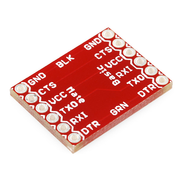
This is a simple board that no one really needs but it sure comes in handy. If you've ever tried to hook up an FTDI to something only to realize you need to swap the TX and RX, maybe you could use this board. Sure, you can grab some jumper wires and make your own, but this little crossover board makes it much easier.
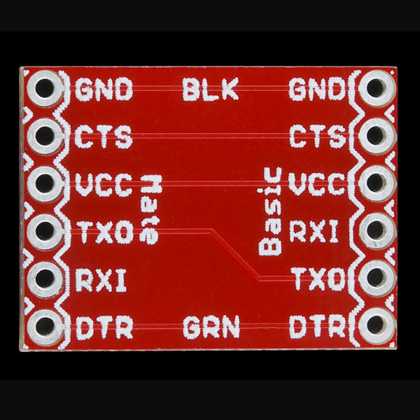
The board has a set of headers going in and a set going out. The TX and RX lines are swapped so you can connect it to a Bluetooth Mate and configure it without having to swap the pins coming from your FTDI.
- [Schematic](http://cdn.sparkfun.com/datasheets/BreakoutBoards/FTDI Crossover-v10.pdf)
- [Eagle Files](http://cdn.sparkfun.com/datasheets/BreakoutBoards/FTDI Crossover-v10.zip)
Crossover Breakout for FTDI Product Help and Resources
Core Skill: Soldering
This skill defines how difficult the soldering is on a particular product. It might be a couple simple solder joints, or require special reflow tools.
Skill Level: Noob - Some basic soldering is required, but it is limited to a just a few pins, basic through-hole soldering, and couple (if any) polarized components. A basic soldering iron is all you should need.
See all skill levels
Comments
Looking for answers to technical questions?
We welcome your comments and suggestions below. However, if you are looking for solutions to technical questions please see our Technical Assistance page.
Customer Reviews
No reviews yet.
It would be nice if this were in the form of a cable. Anyway, I might try making my own.
AKA "null modem" adapter. Everything old is new again!
so, hypothetically this is something i could use to hook up a bluetooth mate to a ftdi cable? so i can set it up to communicate (and auto pair) with another bluetooth chip on a pro mini ?
I am new. Was trying to illustrate concepts for some general board but formatting got messed up.
I tweaked the formatting on your other comment a bit; you just needed a few more newlines.
This is nice. How about DIY wiring ones like these?
o = PTHs for signal, power, ....
# = PTHs tied to ground plane on bottom side.
DIY 6-position translator board with ground plane
+--------+
|# # # #|
|o-o o-o|
|o-o o-o|
|o-o o-o|
|o-o o-o|
|o-o o-o|
|o-o o-o|
+--------+
More general one - more positions and two common columns like this:
DIY Translator board with ground plane -probably 15 or 18 position
+-------------+
|# # # # # #|
| |
|o-o o o o-o|
| | | |
|o-o o o o-o|
| | | |
|o-o o o o-o|
| | | |
~~~~~~~~~~~~~~~
~~~~~~~~~~~~~~~
|o-o o o o-o|
| | | |
|o-o o o o-o|
| |
|# # # # # #|
+-------------+
2-layer thin board, gnd plane bottom, rows labeled 1,2,3,..., columns A,B,C..., useful for stacking up various sensor boards, etc.
This would have been SO useful a few months ago! I was building an arduino and gps board. I actually connected the arduino and gps correctly but got the FTDI and arduino backwards.
Why is TxD and RxD swapped but nothing happens to CTS and DTR ? Should this not be called RTS and RI or something like that ?