- Home
- Product Categories
- Kits
- SparkFun Solid State Relay Kit

SparkFun Solid State Relay Kit
A solid state relay (SSR) is just what it sounds like; an IC that acts like a mechanical relay. They allow you to control high-voltage AC loads from lower voltage DC control circuitry. Solid state relays, however, have several advantages over mechanical relays. One such advantage is that they can be switched by a much lower voltage and at a much lower current than most mechanical relays. Also, because there's no moving contacts, solid state relays can be switched much faster and for much longer periods without wearing out.
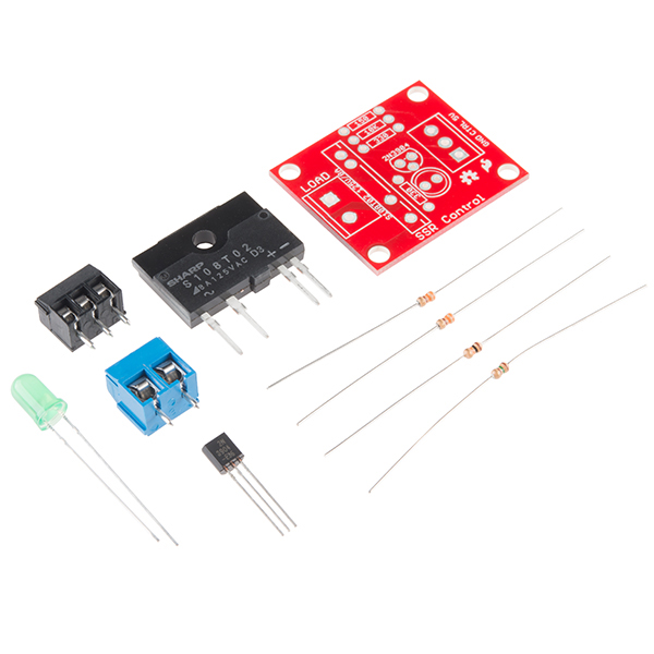
This kit has everything you need to make use of an SSR in your next high-voltage project. After soldering together the through-hole kit, simply attach your AC load and switch it on and off using your microcontroller. This is a great kit for through-hole soldering practice and is really handy for controlling lights, water pumps, fans or any other intermittent high-voltage device.
Note: These work with AC loads only. Great care, safety, and knowledge should be used with high current and voltage.
- Max Signal Current: 50mA
- Min Signal Current: 16mA
- Control Voltage: 5V
- Absolute Maximum Load: 125VAC @ 8A
- 28.5 x 33.3 mm
- Schematic
- Eagle Files
- Datasheet (S108T02F)
SparkFun Solid State Relay Kit Product Help and Resources
Adding a Timed Button to a Project
July 29, 2015
This tutorial will walk you through making a timed power controller for interactive projects. You will learn how to add an on button that will provide power to your project for an amount of time and then turn off again.
Core Skill: Soldering
This skill defines how difficult the soldering is on a particular product. It might be a couple simple solder joints, or require special reflow tools.
Skill Level: Rookie - The number of pins increases, and you will have to determine polarity of components and some of the components might be a bit trickier or close together. You might need solder wick or flux.
See all skill levels
Core Skill: DIY
Whether it's for assembling a kit, hacking an enclosure, or creating your own parts; the DIY skill is all about knowing how to use tools and the techniques associated with them.
Skill Level: Noob - Basic assembly is required. You may need to provide your own basic tools like a screwdriver, hammer or scissors. Power tools or custom parts are not required. Instructions will be included and easy to follow. Sewing may be required, but only with included patterns.
See all skill levels
Core Skill: Electrical Prototyping
If it requires power, you need to know how much, what all the pins do, and how to hook it up. You may need to reference datasheets, schematics, and know the ins and outs of electronics.
Skill Level: Rookie - You may be required to know a bit more about the component, such as orientation, or how to hook it up, in addition to power requirements. You will need to understand polarized components.
See all skill levels
Comments
Looking for answers to technical questions?
We welcome your comments and suggestions below. However, if you are looking for solutions to technical questions please see our Technical Assistance page.
Customer Reviews
No reviews yet.
Panasonic Electric works AQZ202 is a drop in replacement for the triac SSR that uses 2 FETs based so works with AC and DC. The model above is rated for 60 V so *** DO NOT use it for line voltage! *** It is rated for 3 amps CW without heat sink at room temp. Available at Digikey for less than $12. They also have voltage ratings much higher but at low current, and single FET DC versions with lower resistance (hence higher current). In general the FET versions switch lower current than triacs, but work at DC.
It seems like the data sheet says the minimum trigger current is 8mA. But you say 16mA?
There are several problems with this design, some of which are significant because they are safety related.
The PCB layout does not provide adequate creepage distances for the high voltages that one would expect this device to be used with. So if there's a spike in your AC power line, it could arc over and find it's way into your low voltage circuitry with disastrous results. And be really careful about the mounting hardware used on the AC power side of the PCB (especially the mounting hole near pin 1 of the SSR).
Unless you add a heat sink, the SSR is only rated at to handle about 2.5A at room temperature.
A SSR can be more difficult to work with than a conventional relay. When driving loads such as solenoids or motors a snubber circuit may be necessary in order to make the SSR work properly.
And what's with the complicated transistor control circuit? The SSR control input is rated at 16 mA, so just drive it directly (through an appropriate current limit resistor) from a microcontroller output pin. That way a 5V or 3.3V microcontroller could be used.
What would be acceptable creepage distance for 120 VAC ? Should there be a slot in the board, or would it be enough to turn the SSR 90 degrees? Also, is the heatsink tab isolated?
Can you give an advise, please: I'll use TLC5940 with mbed, that gives me a lot of PWM-outs... Can I connect SSR directly to my TLC5940' PWM-out? As I understand, just using mbed's TLC5940-library I can limit a current by 20mA, and set voltage to 1,2V as shown in SSR's DataSheet (S202S02F, that is similar by params to the S108T02, used above).
Thanks in advance!
I'm really interested in using a SSR for controlling some appliances in the kitchen. If this one has some issue, could you (or someone else) recommend a safer design/how-to for me to follow? I don't want to burn my kitchen down. :)
Try this guy: http://www.sparkfun.com/products/9842 - Super clean and simple.
We have a kit to control kitchen appliances based on temperature (but could be used with any voltage/resistance sensor). It's Arduino-compatible and completely open source: http://lowereastkitchen.com.
This would most likely not work well for a kitchen appliance, as they can easily draw more than 8 amps.
hi, i want to switch ON/OFF an audio amp, with a transformer, can I use this chip? I don't know if this can handle inductive loads or if a transformer is considered an inductive load.
i THINK it should work, but I'm not 100% sure. if it's just a linear supply (transformer), it should work.
This comment needs to have a large font and something flashing around it.
Notwithstanding all of the usual dangers of AC mains voltages, at the very minimum, do not connect this to whatever you're using to control it directly. Always, always, always, use an opto-isolator to protect your DC circuitry from a mains voltage. Did I mention to always use an opto-isolator?
I was actually interested in giving this thing a try, but the relay has a zero crossing detector circuit, so no dimming.
the input on these drives an IR LED on a photo triac, already optically isolated
But, but, but...
Ah screw it, I didn't notice that at first. I stand corrected.
I agree completely here. What is with no heatsink on the SSR? This is super dangerous. Something like 10% of SSRs fail in the on state, and these are designed to fail at the "rated" current (8A).
220-240V please...
Seconded. Note that the current board isn't safe for 230V: the creepage distance between high and low voltage is too small.
This is not safe for 220V. Check this :) https://plus.google.com/110230689089207649183/posts/SNyqNQ37BAr
I just designed a custom board with 6 of these, which will be used for switching my house lights. Does anyone have experience using these over a long period of time?,(i.e. years..)
The spec only says that you should design to provide 2x current to the IRED after 5 years. I am trying to figure out how long I can expect these to last , assuming I switch them on/off 2 times / day avg.
HI there, very new to all of this, I have got the IOIO and the Solid State Relay Kit ,had no problem building it, my question is do I take the 5v and ground from the IOIO, OR DO I JUST USE THE CNTR FROM A PIN ON THE IOIO ,supplie the Solid State Relay Kit via an external supply, if anyone has a detailed diagram that would be so useful
HI there, very new to all of this, I have got the IOIO and the Solid State Relay Kit ,had no problem building it, my question is do I take the 5v and ground from the IOIO, OR DO I JUST USE THE CNTR FROM A PIN ON THE IOIO ,supplie the Solid State Relay Kit via an external supply, if anyone has a detailed diagram that would be so useful
What will happen if I use 12v DC current with this?
Can this be used as a very complex switch for low voltage / low current? Specifically I am trying to use it in place of a toggle switch that is only 12V and used for logic so very low load. I looked at using an NPN transistor but I think that I might have a floating ground issue so would like to be able to separate the two sides. Any suggestions on other ways to make a simple digitally controlled switch? Thanks.
Will this heatsink work with this relay kit? https://www.sparkfun.com/products/121
Hi, Considering that relay can push 8 amps, you might have a time when a heat sink is needed. However the heat sink you are looking at is not specifically designed for this relay. It may work fairly well, but when the datasheet mentions the optional accessory heat sink, the one you are looking at is not that specific part. It is simply a universal sink that works in most scenarios. I hope that helps!
Just bought this and received a 240 resistor instead of a 150 as printed on the pcb. Design change?
Sorry for the inconvenience and thanks for bringing this to our attention. We were able to correct several kits before leaving the door! Please contact Customer Service and we'll get a fix sent to you.
I bought this kit and assembled it. Then I modified a brand new 125v, 13 amp, two-prong AC extension cord so that the stranded conductors on the side with "ribbed" insulation pattern were soldered to a solid copper wire which was then connected to to the "LOAD" terminal in the square pad, and the other conductor wrapped in the "smooth" insulation side connected to the other LOAD terminal. I then wrote a small Arduino sketch and connected the control terminals to a Really Bare Bones Board. The control wire goes to Digital 5.
I then plugged a 60 watt incandescent light bulb to the customized extension board, and plugged the extension cord into a surge protector brick. I noticed that within a second or so of doing this, the incandescent light turned on. (The manual switch for the light bulb was switched on.) Then I connected power to the Really Bare Bones board to turn it on. After a few seconds, wham! The entire house electrical circuit that the relay's load is connected to turns off. The circuit breaker had tripped. It took a little while to get things back to normal since that circuit also drives my network switches.
The SSR has no switching functionality at all. I did some Googling to check into this, looking for my mistake. I did have the soldering iron I was using set to over 300 degrees centigrade. I understand the SSR has to be soldered with the temperature under 260 C. Perhaps I destroyed it that way?
Or, did I connect the wrong polarity LOAD wires to the terminals -- accidentally reversing polarity?
Or should I have not used an incandescent light bulb?
Thanks for any help.
I think I miswired the 120v extension cord that is on the load side. Totally my fault. It took some Googling to understand that I only need to connect one conductor of the extension cord to the LOAD side of the relay. I had wired both conductors, one to each side of the load. This post explains how to connect an solid state relay. Only when I saw it did I truly understand my mistake. I feel a little stupid, and the breaker for that house circuit tripped, but I'm better educated now.
If the worst that happened is you tripped a breaker, and you still learned something, then you are doing it right :)
Thank you, Toni. I assume the Sharp relay part is blown. The microcontroller side of this board seems okay, at least the LED works, and I can see that my Really Bare Bones Board is turning digital 5 on and off at the expected intervals. So, I have ordered a new Sharp SSR rather than a new relay board kit. Tomorrow I'll get a new extension cord too. Then desolder the old SSR and solder in the replacement and try again.
Let us know how the repair goes. It'd be great if you are able to get it all fixed up.
You're not the first, and won't be the last. The use of a cheap, purely resistive load that is also easy to see if it is working was a wise choice. A detailed write up (keep the question set in your upper level post!) and you could easily have a fairly high traffic article covering the basics of relay switching of mains current; particularly if you're willing to let it be a something like a hack-a-day "fail of the week", where they try to showcase problem solving.
With no heatsink, at -25c this relay can operate at up to ~3.75 amps. With no heatsink, at 25c this relay can operate at up to ~2.5 amps. With a 100mm100mm2mm heatsink, at 25c this relay can operate at nearly 8 amps.
Please do not try to operate this relay at 8 amps without a large heatsink. Sparkfun, can you stock/link a compatible heatsink?
Can you give an advise, please: I’ll use TLC5940 with mbed, that gives me a lot of PWM-outs… Can I connect SSR directly to my TLC5940' PWM-out? As I understand, just using mbed’s TLC5940-library I can limit a current by 20mA, and set voltage to 1,2V as shown in SSR’s DataSheet (S202S02F, that is similar by params to the S108T02, used above). Should I use driver circuit, or I can straightly connect PWM-out to the + of the SSR?
Thanks in advance!
Is there a reason that you use a transistor to drive the optocoupler? does it draw too much current?
The datasheet is the best place to answer these questions. It notes that the SSR takes 20mA (not including the indicator LED), which is at the upper end of what an I/O port can provide. The transistor allows this to be much less, easing the load on the driving circuit.
Can I dimming a lightbulb with arduino and this module?
No. The S108T02 is a zero-crossing switching relay, for a dimmer you need the non-zero crossing type: S108T01
Would this be a good idea for something like switching a lightbulb with an Arduino?
A demo using mbed is available at http://mbed.org/users/4180_1/notebook/ssr-breakout-boards/
What would be extremely cool is a DPDT version...just saying :)
That would require four SSRs and an inverter (one more transistor) and would stop accurately simulating a mechanical relay whenever the 5V supply was removed. (unless you used Normally Closed SSRs)
Thanks for the reply. I don't really understand the schematics but I'll give it a shot. I'm looking at JP2 and I'm guessing this is where I put my 5V source? Does the fact that I don't have a CTL matter? I'm guessing that would be my trigger to turn the relay on? Actually, could you walk me through the schematic? I have questions pretty much all the way through, for example, what is the purpose of all the resistors? I understand the 330 but not the 10k or 150.
Do you want to email me instead? I think it'd be easier that way. I'm j (dot) thatcher (dot) c (at) gmail (dot) com.
JP2 is where 5V will go. CTL is control, I'm assuming. Putting a high signal on there will turn it on.
This is going to sound like a stupid comment but I'm just learning this stuff. Where are the instructions? I think I figured most of it out from the picture but my LED won't light up so I'm wondering if I have it backwards and minor stuff like that. Can anyone help me out? I'm also wondering some other things.
You're probably right. Having the LED backwards would cause it not to work. The rest of the relay should work regardless of the LED, though, judging by the the schematic. Other questions?
Protip: The schematic is really useful in assembling the board. It doesn't look like the board, but it shows polarities and connections.
Speaking of LEDs not coming on, most relay output boards I have seen (in industry) have the indicator in series with the 'coil' so if the light is on you know the current is flowing through the coil and if the light is off you know that current isn't flowing through the coil. With the current circuit, there are several places where a cold solder joint could cause a false positive or a false negative. i.e. You could have the indicator be on but no output or the output be on but no indicator.
It should also be made more clear in the description of this product that a triac-based SSR does not work with a DC load, it will only work with an AC load.
"Note: These work with AC loads only"
It seems pretty clear to me.
How about 24 VAC, such as a furnace thermostat circuit?
We're wanting to use this for an application that is all logic, we have a 5V logic that needs to go into a 24V logic so we were thinking this would do the trick.
Any idea on reaction times for this?
This relay is only for AC voltages. For your needs you should use a standard relay or use a mosfet and such.
What do you mean "and such"?.
This shows how to do what you need. http://bildr.org/2011/03/high-power-control-with-arduino-and-tip120/
Here are the gerbers, if you're curious. The thermals on the load pins might not be needed -- just as simple as un-checking the box on the polygon in Eagle to remove them.
http://circuitpeople.com/ViewPackage.aspx?id=0feb0413-7886-435d-980a-31058c2ce25f
If the thermal stays, I would opt to route thick fat tracks (bottom & top) together with the pour. I think, the board is relying on the thermal connection at the moment.
I was curious if the skinny traces connecting the pads to the thicker trace would do 8 amps? I'm to tired to calculate it right now.