- Home
- Product Categories
- Arduino Shields
- SparkFun GPS Shield


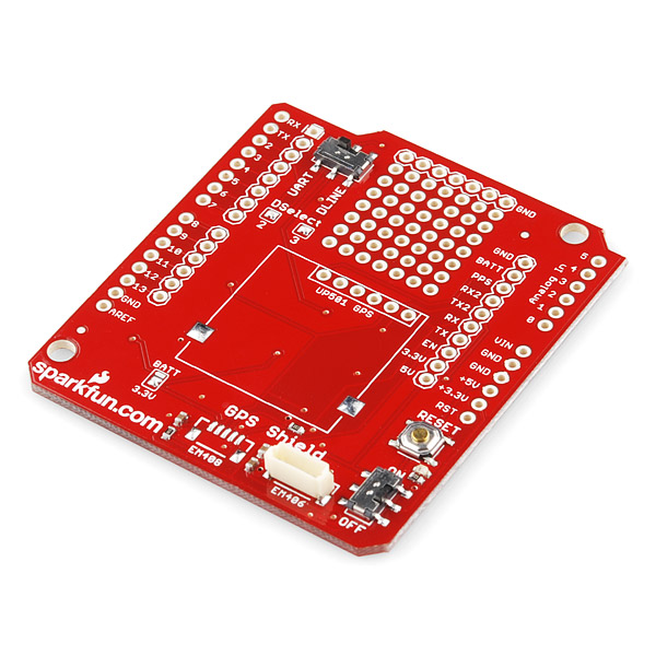
SparkFun GPS Shield
Adding GPS to your Arduino has never been easier. Multiple GPS receivers attach easily to the shield, and with the SparkFun GPS Shield and the example sketch (check below), you will be able to locate your exact position within a few meters. Here's where we are. GPS also gives you amazingly accurate time!
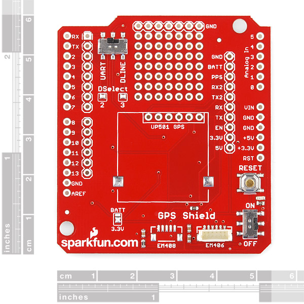
A connector for the popular EM-506 GPS receiver is populated on the board, and footprints for EM-408 and EB-85A connectors are also made available (connectors are not included and can be found below in the related items). There is also a spot for the UP501 GPS module. The regular GPS pins (RX, TX, PPS, etc.) are also broken out to a 10-pin 0.1" pitch header, and a small protoyping area is also provided.
The DLINE/UART switch switches the GPS module's input/output between Arduino's standard TX/RX pins or any digital pins on the Arduino (default setting uses pins 3 and 2 connected to TX and RX, respectively). The DLINE/UART switch must be set to DLINE in order to upload code through the Arduino IDE.
The shield also includes the footprint for a 12mm coin cell battery holder to provide battery backup to the optional EB-85A GPS module.An ON/OFF switch is included which controls power to the GPS module. Additionally, the Arduino reset switch is also brought out.
**Note: **GPS modules are not included with the GPS Shield, and only the EM-406 connector is populated. Headers are also not installed or included, we recommend the 6 and 8-pin stackable headers.
- EM-406 connector populated
- EM-408 and EB-85A connector footprints provided and connected for optional use
- UP501 connector and footprint
- Coin cell battery socket footprint provided and connected for optional battery backup of EB-85A GPS module
- Standard Arduino sized shield
- Prototyping area
- GPS serial and PPS signals broken out to a 0.1" header for additional device connections
- Arduino reset button
- DLINE/UART switch controls serial communications
- ON/OFF switch controls power to GPS module
SparkFun GPS Shield Product Help and Resources
GPS Shield Hookup Guide
March 9, 2015
This tutorial shows how to get started with the SparkFun GPS Shield and read and parse NMEA data with a common GPS receiver.
Core Skill: Soldering
This skill defines how difficult the soldering is on a particular product. It might be a couple simple solder joints, or require special reflow tools.
Skill Level: Rookie - The number of pins increases, and you will have to determine polarity of components and some of the components might be a bit trickier or close together. You might need solder wick or flux.
See all skill levels
Core Skill: Programming
If a board needs code or communicates somehow, you're going to need to know how to program or interface with it. The programming skill is all about communication and code.
Skill Level: Rookie - You will need a better fundamental understand of what code is, and how it works. You will be using beginner-level software and development tools like Arduino. You will be dealing directly with code, but numerous examples and libraries are available. Sensors or shields will communicate with serial or TTL.
See all skill levels
Core Skill: Electrical Prototyping
If it requires power, you need to know how much, what all the pins do, and how to hook it up. You may need to reference datasheets, schematics, and know the ins and outs of electronics.
Skill Level: Rookie - You may be required to know a bit more about the component, such as orientation, or how to hook it up, in addition to power requirements. You will need to understand polarized components.
See all skill levels
Comments
Looking for answers to technical questions?
We welcome your comments and suggestions below. However, if you are looking for solutions to technical questions please see our Technical Assistance page.
Customer Reviews
No reviews yet.
Hy Guys, I hope that will be helpfull for someone. On grabcad.com I have posted a 3d sketch model (stp format) of this board. it’s exported from eagle schema. If ask it’s available also in Alibre format
http://grabcad.com/library/sparkfun-arduino-gps-shield
There is no logic level converter on this shield. The EM-506 module uses 3.3V logic:
"I/O High Level Input Voltage VI H 1.26 __ 3.6 V"
Also, there is mixed information about EM-406 and EM-506. So do they use the same connectors? SPE used to sell connectors for EM-406A. I still have a couple of them.
Is this module (https://www.sparkfun.com/products/12751) compatible with this shield? 'coz it keeps saying that this shield is "EM-406 connector populated" but the module is EM-506.
Thank you in advance!
Hi there!
Yes, the description (should be changed soon) should say EM-506. Our GPS Shield Kit even ships with the EM-506.
https://www.sparkfun.com/products/13199
Will this work with the LS20031 gps and Arduino Uno R3? I'm seeing that UP501 is retired and LS20031 looks similar. Wanted to double check before purchasing.
I plan to buy a GPS shield. Can anybody tell me, how can I controll my GPS from software, that the GPS is ready at the moment? So that the GPS can receive at least 4 satellite, so it can send appropriate data about the position? The shiled will be built into a device, so any visible indicating is useless (i.e blanking LED). The only salution should be a software routine, which report "true", or any boolean-convertable variable that indicates the GPS module ready for positioning. Lot of thanx GF
Check out the Tiny GPS library which has a lot of useful functions. I'm not sure if it has a function specifically to do this, but when a GPS module doesn't have a lock it tends to output 0s for Longitude and Latitude, checking for that should work.
Is this shield compatible with Arduino YUN?
The Yun does not have the hardware serial pins free, meaning you should be able to connect it to the software serial lines. Personally I would skip the shield and just connect the GPS directly.
Wondering the PPS (PIN # 6 of EM 406) is connected or left open in this shield? if not connected how can the issue can be solved??
I need some assistance, I purchased one of this shields for my arduino yun. The GPS i bought outputs in RS232. Does that mean that i would need to attach another board to convert the signal?
Yes. You could alternatively use the prototyping area on this shield to build in your own converter, but this shield isn't designed to work with RS232 as-is.
Please Help me, I have this module and make all the steps, but I use Arduino Leonardo and the example no work, always with all configurations in the shield the sentence "uart_gps.available()" returns false; whats wrong? Is possible to get technical assitence??
Guess the forum is unmonitored so I'll try to answer regarding the GPS shield possible problems. I'd recheck all the soldering on the board to make sure that you don't have a solder bridge between any of the header pins, and that's you haven't missed any connections that should be solder! 90 percent of all problems with electronics is soldering and power related. The fact that the 406 GPS is flashing means that it's not getting a lock for some reason. Have you tried it using the UART pins instead of DLINE? Does it work (get a lock) when just powered and not connected tot he GPS shield?
The first step is to put the shield under a magnifying glass or loop and have a very careful look for any solder bridges or missing solder connections and its best if someone else does it for you because, believe it or not, you'll overlook the same mistake and the more simple the circuit the more chance of a mistake! Been their, done that!
I have the SparkFun GPS shield and the 406 GPS unit. I have confirmed connection between the GPS RX to Arduino TX and GPS TX to Arduino RX with an ohmmeter. I'm running the current example sketch listed under the GPS Shield listing but I get no data. I do get: GPS Shield QuickStart Example Sketch v12 ...waiting for lock... But nothing more. I have open skies and the activity light on the GPS is flashing away but after 7 minutes still nothing is printed out on the serial monitor other than the above two sentences. I have confirmed +5v and GND on the GPS 406 plug. The sketch compiled OK with no errors. I'm using the UNO board and power through the USB from my laptop. Switch is in the DLINE position and the ON/OFF switch is in the ON position. Does the case of the GPS unit have to be totally insulated from the shield? I mounted it with thin double sided tape but on the prototyping area which I assume is not connected to anything. I may try some double sided foam tape to lift it above the board to see if that could be causing a problem. My old Garmin gets a fix in a minute or two in the same location. Does anyone have any idea of what the heck is going on here?
Does the shield has sd card holder footprint?
I'm trying to connect this to an Arduino Mega (https://www.sparkfun.com/products/11061). The shield fits, but it isn't quite flush because the USB connection on the Mega is in the way, so the shield can't go down all the way. The header pins all line up and make a good connection, though. Is this anything to worry about? Sorry, I'm pretty new at this. Thanks!
It appears (from the schematic and a continuity test) that the EM406 PPS is not connected to the PPS break-out. Why is that? and will that be fixed in a later revision of the shield? Thank you!
I'd like to second this.
What about the empty 7 rows of pins , is it a separated circuited that i can connect anything to it ? are the connected vertically or horizontally
are there any steps that have to be avoided to not short the gps with the shield
Is there anyway to turn the GPS sheild off from the arduino? I'd like to be able to save some battery by turning off the GPS when I don't need it. Any ideas?
Besides that, great GPS, worked right out of the box with the example sketch for me.
Can anyone explain what happens if you try and upload code without switching the DLINE/UART switch over? I mean I get that it won't work, but I tend to be pretty forgetful when it comes to that sort of thing, will it damage the receiver in any way?
If you have a GPS connected and the switch is in the UART position, you won't be able to load Arduino sketches, due to bus contention. This won't damage the board. If you switch to DLINE, you can upload your sketch, but now the serial lines on the GPS are moved to pins D2 and D3 (instead of TX and RX) on the Arduino. So you will either need to use NewSoftSerial libraries or switch back to UART after uploading. Hope that helps.
The UP501 RX pin should see 3.3V not the 5V defaul from Arduino. Is there a divider network or something else on the board that keeps the UP501 RX below 5V? I think the answer is no because I'm measuring the UP501 RX pin at 5V -- won' this damage the GPS?
Is it correct the PPS-pin of the EM-406 connector is not connected to anything? Not even a header-pin somewhere on the board?
I just probed it and it appears unconnected, at least on the 7-15-10 board. It seems like it should be wired to the PPS pin on JP1. What's up with that? PPS is a great feature of the 406a!
I'm wondering if the PPS pin is connected on the 5-17-11 board? If not, how hard would it be to disconnect the wire out of the EM-406A connector itself and solder it to the PPS pin?
Has anyone notice that the assembly guide's Shield does not match the current GPS Shield -- http://www.sparkfun.com/tutorials/184 ???
I am not saying this to be mean but there are something’s on the new shield that does not make any sense. There is a little Bat/3.3 jumper above the sparkfun.com logo on image 2 which the pads look like the same SJ1 and SJ2. It's not a through hole connector which Jumper 31-2 is. On the Schematic it shows a battery, but nothing equates to this object (I think it's a jumper 31-2- but it does not reflect the what the part looks like) on the PCB (Batt/3.3V).
The other thing that shows up on the new GPS shield that does not show up on the Schematic is the UP501 GPS silk screen on the PCB. The silk screen pins for the UP501 is not even labeled, unlike everything else is on the GPS shield. YES, there is the EM406 that has six pins, but nothing on the schematic that indicates that it matches up with the UP501 GPS silk screen.
I think the dead horse has been hit enough...
Will someone at Sparkfun please fix all of this? Thanks. -BlackLab.