- Home
- Product Categories
- Kits
- SparkFun Max Power IR LED Kit


SparkFun Max Power IR LED Kit
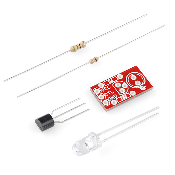
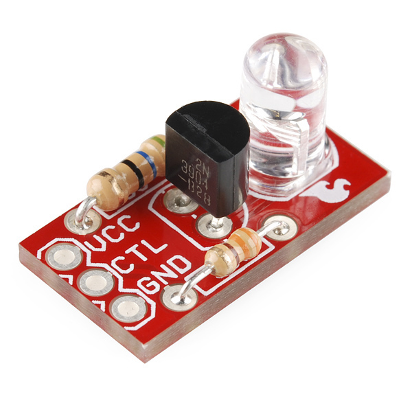
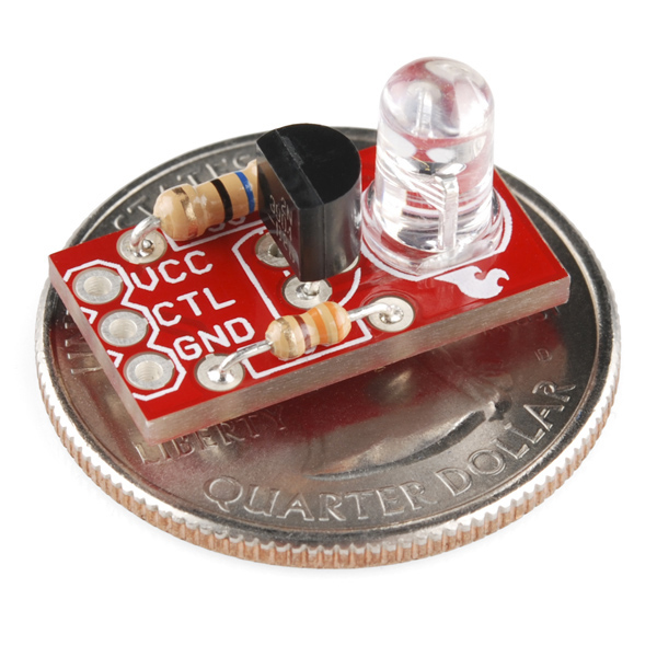
Infrared LEDs are awesome. Along with an IR receiver they can be used for remote control and even basic remote data communication. The only problem is that your Arduino won't drive them to their full potential. The SparkFun Max Power IR LED kit solves this problem by providing you with everything you need to drive a 950nm IR LED properly. Simply solder together this easy through-hole kit and you can switch the LED using a transistor.
Once the kit is assembled, simply provide it with voltage (5V), ground, and connect the CTL pin to a digital pin on your Arduino, and you can drive this kit just like a normal LED. Although the LED won't be visible to your naked eye, you can use a video camera, cell phone camera, or digital camera to see if the LED is working properly.
Replaces:KIT-10662
SparkFun Max Power IR LED Kit Product Help and Resources
Core Skill: Soldering
This skill defines how difficult the soldering is on a particular product. It might be a couple simple solder joints, or require special reflow tools.
Skill Level: Rookie - The number of pins increases, and you will have to determine polarity of components and some of the components might be a bit trickier or close together. You might need solder wick or flux.
See all skill levels
Core Skill: Electrical Prototyping
If it requires power, you need to know how much, what all the pins do, and how to hook it up. You may need to reference datasheets, schematics, and know the ins and outs of electronics.
Skill Level: Rookie - You may be required to know a bit more about the component, such as orientation, or how to hook it up, in addition to power requirements. You will need to understand polarized components.
See all skill levels
Comments
Looking for answers to technical questions?
We welcome your comments and suggestions below. However, if you are looking for solutions to technical questions please see our Technical Assistance page.
Customer Reviews
3 out of 5
Based on 1 ratings:
0 of 1 found this helpful:
too small
Old age, poor eyesight and improper tools were my downfall. In one fell swoop, I managed to solder all three wires of the transistor with a single mound of solder. Does this come in a 5x7 package? Also, do you carry magnifying glasses the size of the ones seen on "The Santa Clause" movie?
In all honesty, I have no idea how to rate this product since my soldering prevents me from trying it out.
Received four of these little critters the other day, and tested them out, using the camera on my iPhone 3G. I observed that two of them lit up very dimly compared to the others. Then I tried the camera on my other phone, an iPhone 4. Now they all lit up brightly. Two of them were even visible with the naked eye, giving off a very weak red color. So there clearly is a difference in the wavelengths of the IR LED's. The datasheet for the IR LED states that the minimum wavelength is 940, and the maximum 950 nm, so I guess that's the explanation.
Could I use this for my Arduino TV-Be-Gone?
or does that require more than one?
Yep, this would work. The TV-B-Gone from adafruit has 4 LEDs, but this only improves the range. The outer 2 are wide angle, the inner two are narrow beam, I believe.
baum
This is designed for 5v, and I was wondering if I run it on 3v, what should I change the value of R2 to?
A helpful piece of info I discovered while meandering in the depths of IR communication - as of I believe the iPhone 4S, the back camera has some sort of IR shield, presumably to get better picture quality. However, the front-facing camera does not. I was able to see the IR LED with the front cam, but not the back. (note - these observations are merely my guesses, I didn't actually look at any sort of datasheet or tech specs)
yeah i toasted my resistors taking it apart again because I used the pictures here as a guide:O(
I don't understand, are the pictures correct? I have assembled as in the pictures, I get 74mA on the led (should be below 50 I suppose), voltage is 1.4v and the led doesn't light up (at least I don't see with my iPhone camera). What could I have done wrong?
EDIT: iPhone 5s doesn't see these, had to use my mac's isight camera to check. Still worried about the current though.
I've heard that TV remotes drive their LEDs at up to 2 A for increased range, and avoid burning them out by using short pulses. Just something to think about when/if you design a new version of this.
Any chance of a 850nm IR version?
Hi, this is a great site, but please be gentle since I'm almost a total noob. :) I did some electronics in high school and am looking to get back into this.
I was looking into the specs of the 2N3904 transistor and comparing it with the 2PN2222 transistor trying to determine why you would use the one you picked. What I came up with are headings like: "Current - Collector (Ic) (Max)", "Voltage - Collector Emitter Breakdown (Max)", "Vce Saturation (Max) @ Ib, Ic", "Current - Collector Cutoff (Max)", and "DC Current Gain (hFE) (Min) @ Ic, Vce".
I recognise some of these, and are a bit sketchy on others. Do you have a site or other reference that you would recommend on learning electronics?
Thanks!
For anyone serious about learning the fundamentals of electronics (as opposed to playing with electronics, which is totally fine), many of us swear by The Art of Electronics by Horowitz and Hill. It's a large but surprisingly readable textbook, which goes into details like the transistor specs you list above. The current edition is some years old and therefore not up to date on the latest trends, but the fundamentals are timeless and solid. (A new edition has been in the works for years and may appear at the end of this year, but don't let that stop you from getting the current edition). If you visit SparkFun, you'll find this book in many of our offices, bristling with post-it note page markers.
You know in the last 50 year bigger and better things have been made, but a transistor is a transistor,even if it's its a tin can or SMD. I find that the older references tend to be just as enlightening as the newer stuff with out being boged down with the latest gismos. Personally if your really just starting This book is great, it will help with the basis with out getting terribly complicated right off the bat, and it come with a lot of basic project that are breadboard friendly.
can I use this as a transmitter in a communication link based on FPGA? And if the answer is yes which photodetector do u recommend I should use as the receiver?
This board should work fine with an FPGA. For all things IR, the TSOP382 is a pretty good way to go.
"Note: This revision fixes our mistake from the last version and should now source the 50mA maximum current that the LED is rated for"
I thought we are not recommended to source more than 40mA from Arduino, not sure if this is with any other controller though
The 50mA driving the LED is not coming from the Arduino pin, but from the 5V supply. The point of this board is so you don't draw that amount of current from your Arduino pin and damage the chip. In this case, it is more in the realm of 10mA which the chip can easily handle.
Wacky question: Lets say I wanted to transmit to 20 infrared receivers, but all sending the same signal simultaneously. Is there a way I can wire these up in series so they share power, then use one arduino pin to control them all?
Do you think it would be easier to control one IR LED, then use fiber optics to split and route the signal to these 20 receivers? #madscience
sorry for the question but I know nothing about electronics. can this board be used with just a battery and momentary switch to make an bright IR light pen? I just need on or off. also can a 3-AAA Battery Holder in serries power it?
Yes, this kit will work for you, and will run fine on 3 x AAA batteries (4.5V). You could do it slightly simpler with just the LED and the 56 Ohm resistor if you wanted (the transistor is there to allow a weak computer pin to turn the LED on and off), but it won't hurt anything to use the full kit for your application. Note that this is a kit of parts, so you'll need to solder to put it together (it's easy, see our tutorials).
How far can these typically work from a basic controller? Like the basic keychain remote...
http://mbed.org/users/4180_1/notebook/ir-and-rf-remote-controls/ has a code example for mbed sending characters to the matching 38Khz receiver breakout
Does this work with an arduino pro mini 3.3v out of the box? so 5v on vcc and 3.3v on ctl?
I seem to have a problem with this item. I connected it to my arduino to control my TV, and it worked great. But when the distance between the LED and the TV gets over approx 2 meters, it stops from working while my regular TV remote works from much greater distance. I've soldered the resistors as printed on the board and not as presented in the photo. Any ideas?
Would it be possible to run this board without Arduino? As I remember Arduino HIGH digital pin has 5V - would it be possible to connect VCC and CTR pads to get led working?
(Forgot I've posted this question) Turns out is was a faulty wire with high resistance.
it,s a great quality led a nice little kit i use them in projects. and it was my kids first circuit board.
What I really want to know is why did they use "P = I^2 * R" and not just "P = I*V"
Obviously its the same, but for me the latter is "simpler"....
bah... just a thought and totally a matter of opinion... it did make me think twice and doubt my self a bit...
Im more puzzled about why the equation includes a 0.7 voltage drop. The transistor is in saturation mode, not active mode, and the voltage drop, if not negligible, should be around 0.2? Or am I getting it wrong?
//R
V, I, R, P can be related in many different ways. Why limit to just one? You can probably factor in the speed of light to the V=IR equation for all I know.
From wikipedia:
1 volt = (kg x m^2)/(A x s^2)
1 meter = the length of the path travelled by light in vacuum in 1⁄299,792,458 of a second.
So...
1 volt = (kg x (distance travelled by light in 1⁄299,792,458 of a second)^2)/(A x s^2)
and ohm's law:
(kg x (distance travelled by light in 1⁄299,792,458 of a second)^2)/(A x s^2) = I x R
:)
baum
do we have any arduino code example? I can't find how to use it
if your looking for arduino codes then go on there website download there programmer that will set you strait!
This Arduino library comes with a few good examples:
http://www.arcfn.com/2009/08/multi-protocol-infrared-remote-library.html
Can I run this off a IR receiver Dodie/Transistor?
Like to use this as a re-director for my IR Remote controls.
Not with what we have. The IR Receiver diode decodes the signal, so it will no longer be recognized by the thing you are trying to control. You will need to use a receiver which doesn't decode it.
Resistors backwards and in the wrong spots, eh? You sure this version is "error-free"? :P
(looks like there's another jester 'round these parts, may need be a Jester-off!)
Ha! The resistors in the picture are the wrong way around.
They're also upside-down if you look closely.