- Home
- Product Categories
- IMU
- 9 Degrees of Freedom - Razor IMU

9 Degrees of Freedom - Razor IMU
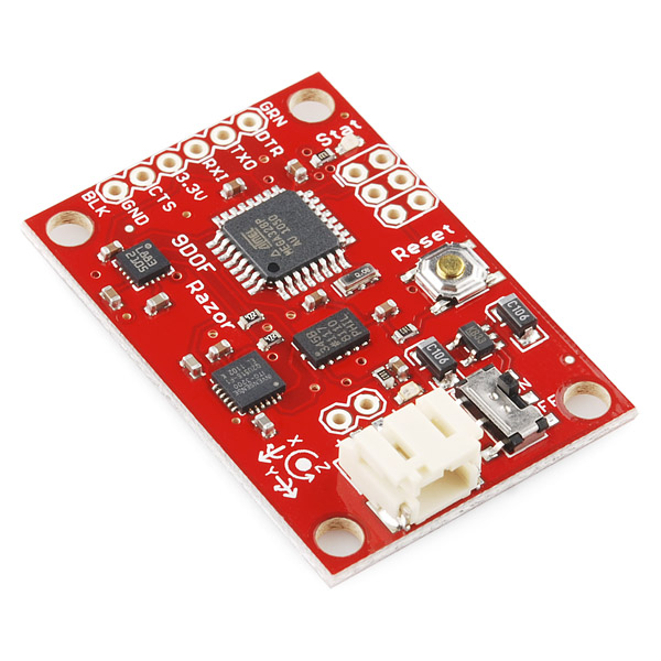
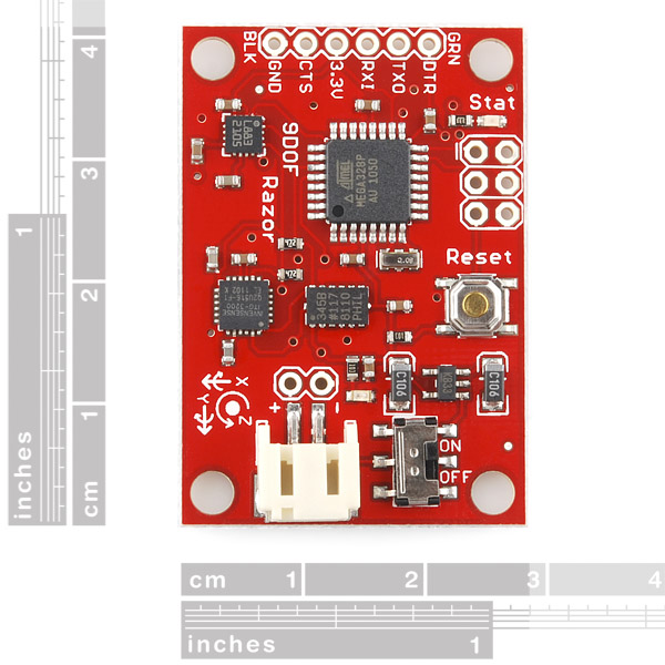
The 9DOF Razor IMU incorporates three sensors - an ITG-3200 (MEMS triple-axis gyro), ADXL345 (triple-axis accelerometer), and HMC5883L (triple-axis magnetometer) - to give you nine degrees of inertial measurement. The outputs of all sensors are processed by an on-board ATmega328 and output over a serial interface. This enables the 9DOF Razor to be used as a very powerful control mechanism for UAVs, autonomous vehicles and image stabilization systems.
The board comes programmed with the 8MHz Arduino bootloader (stk500v1) and some example firmware that demos the outputs of all the sensors. Simply connect to the serial TX and RX pins with a 3.3V FTDI Basic Breakout, open a terminal program to 57600bps and a menu will guide you through testing the sensors. You can use the Arduino IDE to program your code onto the 9DOF, just select the 'Arduino Pro or Pro Mini (3.3v, 8mhz) w/ATmega328' as your board.
The 9DOF operates at 3.3VDC; any power supplied to the white JST connector will be regulated down to this operating voltage - our LiPo batteries are an excellent power supply choice. The output header is designed to mate with our 3.3V FTDI Basic Breakout board, so you can easily connect the board to a computer's USB port. Or, for a wireless solution, it can be connected to the Bluetooth Mate or an XBee Explorer.
Having a hard time picking an IMU? Our Accelerometer, Gyro, and IMU Buying Guide might help!
Note: This product is a collaboration with Jordi Munoz of 3d Robotics. A portion of each sales goes back to them for product support and continued development.
- 9 Degrees of Freedom on a single, flat board:
- ITG-3200 - triple-axis digital-output gyroscope
- ADXL345 - 13-bit resolution, ±16g, triple-axis accelerometer
- HMC5883L - triple-axis, digital magnetometer
- Outputs of all sensors processed by on-board ATmega328 and sent out via a serial stream
- Autorun feature and help menu integrated into the example firmware
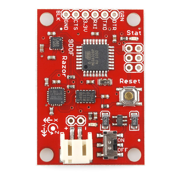
- Output pins match up with FTDI Basic Breakout, Bluetooth Mate, XBee Explorer
- 3.5-16VDC input
- ON-OFF control switch and reset switch
- 1.1" x 1.6" (28 x 41mm)
- Schematic
- Eagle Files
- Datasheet (ITG-3200)
- Datasheet (ADXL345)
- Datasheet (HMC5883L)
- AHRS Code
- AHRS/Head-tracker Tutorial (Thanks Peter!)
- GitHub
9 Degrees of Freedom - Razor IMU Product Help and Resources
Core Skill: Soldering
This skill defines how difficult the soldering is on a particular product. It might be a couple simple solder joints, or require special reflow tools.
Skill Level: Noob - Some basic soldering is required, but it is limited to a just a few pins, basic through-hole soldering, and couple (if any) polarized components. A basic soldering iron is all you should need.
See all skill levels
Core Skill: Programming
If a board needs code or communicates somehow, you're going to need to know how to program or interface with it. The programming skill is all about communication and code.
Skill Level: Rookie - You will need a better fundamental understand of what code is, and how it works. You will be using beginner-level software and development tools like Arduino. You will be dealing directly with code, but numerous examples and libraries are available. Sensors or shields will communicate with serial or TTL.
See all skill levels
Core Skill: Electrical Prototyping
If it requires power, you need to know how much, what all the pins do, and how to hook it up. You may need to reference datasheets, schematics, and know the ins and outs of electronics.
Skill Level: Competent - You will be required to reference a datasheet or schematic to know how to use a component. Your knowledge of a datasheet will only require basic features like power requirements, pinouts, or communications type. Also, you may need a power supply that?s greater than 12V or more than 1A worth of current.
See all skill levels
Comments
Looking for answers to technical questions?
We welcome your comments and suggestions below. However, if you are looking for solutions to technical questions please see our Technical Assistance page.
Customer Reviews
4.3 out of 5
Based on 12 ratings:
1 of 1 found this helpful:
Easy for a begginer and excellent for a professional!
The plate is easy to operate and very convenient to integrate it into your prototypes with excellent performance! Congratulations, great job!
1 of 1 found this helpful:
Great device!
I'm using the Razor IMU for long time. I hope my students will love it as much as I do.
3 of 3 found this helpful:
Great Product From Sparkfun
I have used a few industrial altitude, heading, and reference systems (AHRS) that cost $1,500 per device. It takes a great deal of time and knowledge to create such a device at an industrial level. However, with the AHRS code supplied I was able to turn this into a great AHRS with little effort and I was amazed how accurate it was. I still can't believe how much this device costs but if you compare that to other AHRS devices it is a good price.
This is one those items you really really want to do everything it claims it can and it ACTUALLY DOES.
Brilliant design, fully functional and simply works EXACTLY as it says it does. Within minutes of unpacking the IMU it was actually navigating the platform. Stability is excellent as is the reliability. The battery connection and switch is actually very useful. You have to watch your magnetic interference but that is the same with any Magnetometer. Absolutely brilliant piece of electronics and an absolute must have for anyone looking for a motion sensor or a reliable IMU.
really fun all in one unit
I didn't have any trouble getting it up and running by following the directions in the links on the product page. it takes some effort to get it calibrated, but not unreasonable for the number of axes this thing has. nice work, sparkfun!
Works beautifully.
I used a 4-pin (no DTR/CTS) FTDI cable so it took a few tries for me to reset it manually at the right time to upload the firmware I need for ROS. Once I accomplished that, it was quite impressive to watch as I swung it on the end of the cable. I have not mounted it to a vehicle yet.
IMU - 9DOF
Excellent. Works as advertised. I wouldn't hesitate getting this product.
9DOF Razor IMU?
I dunno, I'll tell you during the AVC! :D
I wired it, but haven't gone into the nitty gritty details... when I ordered it, didn't realize there was an Arduino (ATMEGA) chip in it! o.O No wonder I paid $40 more than I thought, but that's my fault. :)
Can't be programmed
It is impossible to download the program in the tutorial/guide rendering this product unusable. Other users have apparently had this problem as well. It just gives a stk_500 getsync() error every time you try to download the arduino code by following the tutorial to the letter. The tutorial itself might be horribly out of date.
It is possible something in the Arduino IDE has changed since this code was written. Please email techsupport@sparkfun.com and send a screenshot of your error if possible and they should be able to help you get the code working.
Good reference tool for engineers.
The open source helps our engineers to understand how the magnetometer and the accelerometer work. This in turn shortens our development time for our application. I also appreciate that part the proceed of the sale is to continue to help development of new products.
0 of 2 found this helpful:
I am returning it
I reviewed the 9DOF Razor IMU and thought it would be good for a project in which I would use an Arduino Uno to make an accelerometer.
Upon further review, this appears to be too difficult a task for someone like myself, who is very new to projects such as these.
I have connected the IMU to the FTDI breakout 3.3V and then plugged via usb to my pc. Then i used a serial terminal (both CoolTerm and the Arduino IDE terminal) to test the example firmware Although the firmware loaded alright showing a menu,when i pressed various buttons i received no response. More specifically the TX LED on the FTDI lit up but the receiving LED on the IMU did not light up. Also i tried the AHRS/Head-tracker Tutorial but when trying to upload the arduino sketches got the following error: avrdude: stk500_getsync(): not in sync: resp=0x00 avrdude: stk500_recv(): programmer is not responding
Any ideas how to fix this?
Does anybody know how to change the range of the ADXL345 accelerometers from 2g to 4g or to other values that are 8g and 16g? By using Peter's code, not by using ADXL345's library provided by Sparkfun. If we are able to change the range of accelerometers, do you think we need to do accelerometer calibration again?
I learned how to set the range and resolution (scale factor) of ADXL245. Let me report here for reference for those who might need different ranges for the accelerometers:
/* 0x09 = B00001001 --> fourth bit from right is D3 of DATA_FORMAT Register (0x31) and * when it is 1, it means full resolution. D1 and D0 are range bits (see page 17 Table 18 * of ADXL345 datasheet by Analog Devices). * (D1,D0) = (0,0) sets accelerometers to (+/-)2g range. * (D1,D0) = (0,1) sets accelerometers to (+/-)4g range. * (D1,D0) = (1,0) sets accelerometers to (+/-)8g range. * (D1,D0) = (1,1) sets accelerometers to (+/-)16g range. * When D3 is set to 1, independent of range accuracy (also called scale factor in Table 1) * remains approximately 4mg/LSB (typically it is (maxRange - minRange) / numberOfBits, e.g., * (2-(-2))/2^10 = 0.0039mg/LSB = 3.9g/LSB, e.g., (4-(-4))/2^10 = 7.8g/LSB so D3=1 enables * increment of usable bits from 10 to 11 hence the resolution maintains (4-(-4))/2^11 = 3.9g/LSB) * 0x08 means (+/-)2g and 10 bits (full resolution) used --> 3.9mg/LSB * 0x09 means (+/-)4g and 11 bits (full resolution) used --> 3.9mg/LSB * 0x0A means (+/-)8g and 12 bits (full resolution) used --> 3.9mg/LSB * 0x0B means (+/-)16g and 13 bits (full resolution) used --> 3.9mg/LSB * 0x00 means (+/-)2g and 10 bits (fixed resolution) used --> 3.9mg/LSB * 0x01 means (+/-)4g and 10 bits (fixed resolution) used --> 7.8mg/LSB * 0x02 means (+/-)8g and 10 bits (fixed resolution) used --> 15.6mg/LSB * 0x03 means (+/-)16g and 10 bits (fixed resolution) used --> 31.2mg/LSB */
hi this is yuvaram form india. i got razor imu before a month and i am having trouble uploading AHRS code to the board (following this tutorial) https://github.com/ptrbrtz/razor-9dof-ahrs/wiki/Tutorial
after making all the needed selection of board ports etc i am having this error https://drive.google.com/open?id=0BzmnMmsPbJkVa2xUalZGYWo4Z00
if i try commending out these line and upload it . this is what i am ending with https://drive.google.com/open?id=0BzmnMmsPbJkVYkZJRVFSWmo2Vk0
this is my hardware setup https://drive.google.com/open?id=0BzmnMmsPbJkVWnZ1dGR0MXhmOXc
i am not sure about this usb to serial converter . it says 3.3v ,but i am not sure about it .in case if the converter is 5v , is there any way of converting it to 3.3v .
it will be a great help if someone can point me in correct direction thanks
I'm using this on a beaglebone board just attempting to use the UART input in C. I have it communicating and seem to get some information out (I can get angles), but I'm having trouble configuring the output stream and reading that. Has anyone done this or could you offer me any pointers/example code?
I just saw that Honeywell released and EOL notice for the HMC5883L with no plans for a replacement part. Does anyone know if there are plans to release a new 9dof board with a different magnetometer?
We are looking into a replacement for this board but we don't have any specs at the moment.
I have this connected to a Bluetooth Mate Gold. It writes data all the time (using Serial.Println), and checks Serial.available() to look for incoming commands. Is there a scenario in which the CPU would reset due to a serial read failure/timeout/etc.? I didn't think there was any way to soft-reset the board, but I'm seeing some global variables (particularly a sequence number) revert to their initial state in a way that looks like the CPU is rebooting when I stress the Bluetooth connection. Anyone have any idea what circumstances cause a reboot? Thanks!
Their is a serial buffer that takes in data whenever it is sent. Once it overflows, then you loose data, but it shouldn't go any farther than that. The serial buffer isn't very big, so it should overflow very quickly.
The only thing I'm aware of that might cause a reboot is excess current draw. Checking what you might have drawing a bunch of current all at once (like one of the large Sharp IR sensors), or something that might suddenly put a big voltage spike on the line, such as a large servo or a DC motor.
The "AHRS/Head-tracker Tutorial" is great! Anyone using this board should work through this tutorial.
The links in the Documents section of this page could use some cleanup. Ignore the AHRS Code link. It points to a zip file containing code for a previous version of this board, and won't work on the SEN10736. Also ignore the Python Graphic Interface link, which is just a youtube video showing a graphic display of the output. If you search github you can find the source for the python app, but it depends on an earlier version of firmware which doesn't run on the SEN10736. The GitHub link leads to the firmware that sparkfun installs on the board they ship. Note: this does not make it an IMU - it only prints the raw data. The really valuable link is the AHRS/Head-tracker Tutorial (long) by Peter Bartz, which contains links to new firmware for the board which does make it an IMU, instructions on how to calibrate it, and a processing app that displays the IMU output.
Thanks for reminding us on this! It's in the system to get this all cleaned up and get a brand new, shiny hookup guide for everyone. It's just been delayed with moving buildings and a few new big projects (like the Edison).
I am trying to run the majority of my data analysis for this device through Matlab. Does anyone know if there is a guide/tutorial on on how to get the basic set-up with readings from the 3 sensors?
Hi,
Great to see that the new AHRS has been updated for the new board. I was having a lot of trouble getting the FreeIMU firmware working properly with this board. It looks like Sparkfun is now contributing some of the proceeds to Jordi Munoz, who created the AHRS code. This seems like a very fair outcome seeing as though the board is effectively useless without the right code.
In the AHRS code it appears as though there is a small error. The gyro x & y have been swapped around. This is very easy to fix though, I have included the necessary change below, but I think it should be updated on the code so that others don't have this problem.
Cheers,
Mike
---Code fix ---Swap around gryo x & y values GYRO[1] = ((((int)buff[0]) << 8) | buff[1]); // X axis GYRO[0] = ((((int)buff[2]) << 8) | buff[3]); // Y axis GYRO[2] = ((((int)buff[4]) << 8) | buff[5]); // Z axis
---Change gyro x to negative int SENSOR_SIGN[9] = {-1,-1,-1,1,1,1,-1,-1,-1};
Hi Michael,
I was just about to release a tutorial and a updated and extended version of the AHRS code, because it seemed it wasn't developed any longer and I had already done it a while ago. Now there is an update, but nevertheless I still want to throw it out, because I think it has some useful features (like sensor calibration, binary output mode, etc) and test program which is easier to run (because it uses Processing instead of Python).
But I only own the predecessor of this board (SEN-10125, on which it works better than the original) and I can't test if the code runs on this one too. As I see it, the only difference in using the new magnetometer is swapping y and z registers.
It would be very very cool if you could test my code and see if it works! So I can give back the world some open code instead of just taking all the time :)
Here's the link: dev.qu.tu-berlin.de/projects/sf-razor-9dof-ahrs/files
It's just uploading the Arduino program and then starting the Processing sketch (using Processing 1.2.1: processing.org/download; versions 1.5 and 1.5.1 have a serial bug).
Would be really great if you could do that!
Cheers, Peter
Or maybe any one else could help me out here? My email address can also be found on dev.qu.tu-berlin.de/projects/sf-razor-9dof-ahrs
Thank you so much PeterBa. Tested your code here and it works very well. I have the 10736 version here and tested it with your processing and arduino code. Seems to work very well. I may need to do a little calibration before it's perfect so I look forward to seeing this section of your tutorial. Let me know if I can help in any way.
P.S. The latest code from a1ronzo also works now with the fixes suggested by michaelt88.
Cool! Thanks a lot, mrgoblin!! So it's release-ready :)
I just uploaded the final firmware version on the files page.
I also completed the Tutorial and added the section about sensor calibration.
Hope this will be useful to some people. Happy tracking!
this is great. I was looking for something just like this. I have an older version of the board but I don't see any issue integrating your calibrations. I'll let you know how it goes.
PeterBa, great work. The software and tutorial you posted is way more useful than the one SF provided. Calibration is a little tricky, but once you get it, you'll wonder how you ever used the SF code without it.
The product post should probably be amended to say: "Note: This product is a collaboration with PeterBa. A portion of each sales goes back to him for product support and continued development."
Thanks so much for this great contribution.
Thank you dds21! Good to hear you like it!
Is the code compatible with the 9DOF stick from sparkfun? I believe all the chips are the same at this point, so would it just be a question of reorienting the axes?
Hi, I don't own the 9DOF stick, but like you said: It should work, but you'd have to reorder the sensor axes in this file: https://dev.qu.tu-berlin.de/projects/sf-razor-9dof-ahrs/repository/entry/trunk/Arduino/Razor_AHRS/Sensors.pde. If you want, let me know when you have it.. I can incorporate it into the Firmware. You can also drop me a mail.
I'm having the same problem with the 10724. It appears that the MAG is rotated 90 deg CCW on the board compared to the Razor so that X is now Y and Y is -X. I've tried changing the SENSOR_SIGN value and the magnetom[] axis but I am still missing something. Any help?
Hmm, I had a look at the datasheets and it seems the y accelerometer axis is not labeled right on the board, it should point in the opposite direction...
But other than that I see it like you said: magnetomter X is Y and Y is -X. You can send me your changed code via email and I have a look, if you want.
The forward direction should be towards the connector, too...
That has been a source of confusion. When I looked at the data sheets, it looked like the Y direction was toward the hole and X was to the right for the Accel and the Gyro, but the Mag has the Y to the right and X toward the 4 hole row.
Got it! I changed around the values in the SENSOR_SIGN array to {-1,-1,-1,1,1,1,1,-1,-1} in Razor_AHRS.ino and switched the buffer addresses for magnitom[0], magnitom[1] in Sensors.ino.
Works as expected now.
Ah, so you're using the (older) SF9DOF_AHRS code and not the Razor AHRS Firmware. I can only speak for the latter one... Could someone try this? In Sensors.pde change the block in Read_Magn() to this:
And you have to set HW__RAZOR_VERSION in Razor_AHRS.pde according to which magnetometer is on your 9DOF Stick. The newer Stick version 10724 matches Razor version 10736, the older Stick matches Razor version 10125.
Seems my previous post was too long and got truncated...
Just wanted to hint, that you have to set HW__RAZOR_VERSION in Razor_AHRS.pde according to which magnetometer is on your 9DOF Stick. The newer Stick version 10724 matches Razor version 10736, the older Stick matches Razor version 10125.
I did get it to work using the 1.3.3 Razor_AHRS code. I may have edited the post above after you saw it.
Ah ok, didn't see it.
For everyone else: I updated the Razor AHRS Firmware, so it now also supports the current 9DOF Sensor Stick as well as the previous version!
Hi Michelt88,
I have somehow managed to get mine working with FreeIMU (thanks fabio) by using a workaround. I comment out the gyro feedback resulting into a more stable behavior. Even if this is not a perfect solution it removes the my drift on the yaw axis. Check out Simple-Sensors.co.uk It works for me for relatively low dynamic behavior.
I got an LabVIEW implementation of an AHRS with sensor data from this IMU:
http://code.google.com/p/labview-quaternion-ahrs/
Youtube vid of the stuff in action:
http://www.youtube.com/watch?v=-uKoqIaFCpU
Don't expect to get a working out of the box AHRS with this board and the associated software (or the Mongoose software) without a correct calibration of the magnetometer ... On mine, I had large hard-iron and non negligible soft-iron errors
Did you actually get the AHRS code to work? I've found that the code that is linked to does not support this version of the board.
The code under "9DOF AHRS Code Base" is not using the ITG-3200 gyro. It is using the old analog gyros which doesn't work with the ITG-3200 and I2C. This can't be the code you are shipping with, where is that code? The "updated" code is just some libraries for the ITG3200, not full Razor code.
The code that ships on the 9DOF is found in the Test Firmware link in the documents section above. This code simply outputs raw values from the sensors.
Ah, so this is a "develop your own imbedded-code IMU board" not a "ready to be used as an IMU board". Personally, I would make that more clear in the description. Thanks for the reply! :)
The product description is extremely misleading. I understand that the unit ships with a test code. It also very clearly states that there is an AHRS firmware the allows you to use this as an AHRS.
Upon not being able to get any kind of correct data out of the linked to AHRS code, I wrote tech support asking if I am doing something wrong. Here was the response:
"...AHRS firmware is written by a 3rd party and has not been updated to use the ITG3200 yet. It also looks like in the past 6 months we've updated the magnetometer so its possible the code hasn't been updated for that either."
I appreciate tech supports honesty and I wish the product description would have been half as clear because knowing what I know now, I would not have bought this unit.
I purchased this board based on my hope (reading the production description) that it would be an elegant, relatively straightforward way to add an AHRS to my various projects. I've tried the 9DOF AHRS Code base that is provided above. It is out of date and doesn't work. It doesn't read the Magnetometer correctly. I've tried the "Updated Code", but that isn't really AHRS code. I see major confusion in the forum here about what AHRS firmware code will actually work, along with suggestions to try using the firmware of competing products (which I've tried and they don't work either). I've tried them all with no good results.
So, my question is this: Does anyone (at Sparkfun or in the forum) have a link to AHRS firmware that actually works on this board? Is anyone at all using this version of this product successfully? It seems like this is a very cool and important product for Sparkfun. If someone could link me to some functional AHRS that would be great.
Any help would be appreciated.
Robert451; I just received my board this week and have gone through the same frustrations as everyone else here (Poor or non-existent Magnetometer readings). A little research into the AHRS sample code previously linked(SF9DOF_AHRS link appears to have been removed) reveals a sequence of instructions in the I2C.pde file that may be at the heart of most problems. Looks like problem originates with the fact the the AHRS third party code was written for the previous Razor board which used the HMC5843 chip. The storage registers for the XYZ locations are in that order, however on the HMC5883chip the same registers hold the XZY data. When the code executes and reads the HMC5883 data it processes it according to the HMC5843 register sequence and generates garbage for yaw indications. I've tried different combination of register read sequences with varied but inconsistent results. Any programmer out there might have better luck.
Unfortunately, we do not host the AHRS code, so we have no control over when it gets revised. However, the example/test code on future builds should work now with the new v22 firmware revision. See the [github repo]{http://github.com/a1ronzo/SparkFun-9DOF-Razor-IMU-Test-Firmware} for the updated v22 hex file. Also, keep in mind, SparkFun's test firmware is only a demo of the sensors and does not implement AHRS.
What is the license for the AHRS code? Perhaps you should fork it, and then you can always make sure there is a version that works with your product. Better to have a version that may be out of date than a version that doesn't work at all. Based on comments from other people, this looks like a pretty serious issue. I'd be pretty annoyed if I spent $125 on a board that said it was compatible with the AHRS code, only to find out that, uh, its not compatible with the AHRS code.
I managed to get something working using http://code.google.com/p/mongoose-9dof-imu/
"ckdevices" seem to be making a business out of reading complaints and making better products than Sparkfun. This isn't an inexpensive board. Too bad it doesn't work out of the box.
Robert451,
You are right. There is MAJOR confusion. I've got an older Razor and the magnetometer just doesn't work at all. Have asked SF about a hardware patch (see above) but heard nothing. You've tried the latest board and still have problems - which doesn't make me want to buy one after I've already bought one that doesn't work and they can't tell me how to fix it.
As for code then I'm trying to create a plain vanilla AHRS/DCM system using WebbotLib (http://webbot.org.uk) that can be adapted to work with ANY gyro/accelerometer plus compass or magnetometer. Not released yet but if you want a .hex file to program the Razor with then give me a shout on webbot@webbot.org.uk
Perhaps we can "get there" together since SF and their suggested AHRS code are totally out of sync.
Perhaps SF should take lessons from the Mongoose board. The latter are clever enough to add an I2C header so that you can, at least, use other gyros/accel/magnetometers etc plus add any other I2C device.
The issue was a bug in the test/example firmware, not a hardware defect. The new firmware revision v22 has been pushed to the [github repo]{http://github.com/a1ronzo/SparkFun-9DOF-Razor-IMU-Test-Firmware} and all future builds will have this fix. Sorry for the confusion everybody!
So how do I upload this new revision of software using Arduino interface as its not a .ino or .pde file?
Unfortunately, the demo/test code was written before we standardized all of our code to Arduino. The board does use an Arduino bootloader, so you can still use avrdude to load the hex file. If you look at the verbose output when you try and load code over arduino, you can copy the avrdude command and add the hex file from the repo to program the board.
EDIT: Here is a good avrdude tutorial. Use programmer flag stk500v2 to use the bootloader.
I have a question regarding connecting the Razor imu with a BLE Mate 2. I want to monitor the data being send on my pc so I want to connect it to the FTDI SmartBasic board. I am wondering what pin I could use form the Razor as a 'Select pin'. Could I potentially use the 'Reset' or any of the spi pins to do this ? Could someone recommend a better technique ? Thanks!
This board is well, but it should have some GPIO pins.
I have this board and the WRL-11373 XBee Explorer, which are claimed to be pin compatible with each other. However, the labelling of the pins seems to indicate they aren't.
The 6 pads on the WRL-11373 are: Unmarked pin GND 5V DOUT DIN Unmarked pin
And on the SEN-10736 they are: GRN/DTR TX0 RX1 3.3V CTS GND/BLK
Is one of these boards mislabeled? Is there a proper description somewhere for wiring these two boards together?
Thanks! -Eric
Anyone made a comparison between this and the Microchip MM7150?
I was wondering if this board has enough pins broken out to add a micro-SD card over SPI to do data recording (so the Atmega328p onboard would be the master). I took a look at the schematic and it looks like the ICSP pins are broken out, but I'm not sure if an SS pin is broken out to be used.
Do you have CAD models of this board (STEP preferably)? Or at least a PDF of a dimensioned drawing?
I have followed the tutorial up to the point of loading the firmware. The code will not load with multiple errors: " 'value' was not declared in this scope." I am communicating with the board, the on board demo works fine. Any ideas will be appreciated.
Hi Guys, I work for a shade sail company and we measure up our sails just using an ordinary tape measure. Is it possible to use this IMU to create a device for taking the measurements instead? All we need is xyz positions relative to a starting position (dead reckoning).
I know there is creep in these devices but we will only need 3-5 readings, with an accuracy of 1cm, over a maximum plan distance of 15m (back and forth). This doesn't seem like excessive requirements, but I am unsure as to what is deemed "reasonable" accuracy with these things. I will probably have a go anyway, but just wondering if I am wasting my time.
Any help is much appreciated. Many Thanks!
Josh
I tried to read out the sensor values with the pre-flashed example firmware (v23) by connecting the rx and tx ports to an Arduino Mega Board. All I get is:
ITG: GOOD HMC: GOOD ADXL: GOOD
9DOF IMU Firmware v23
No data is transferred afterwards. Does anyone know how to fix this problem?
I'm just in the early phase of considering which products to use for a project of mine. I want to be able to have AHRS data, GPS, and 802.11 Wifi in the same package. Does anyone know if it is possible to connect both Wifi up (using XBee Explorer) and also interface to a GPS such as LS20031? I saw that arduIMU was another option (not currently in stock).
Thanks :-)
Hi! I'm trying to write some code for an UAV project using your 9DOF Razor IMU together with an Arduino Due. Accelerometer readings: OK, Magnetic readings: OK But I can't figure out the gyroscopic readings to calculate bank angle etc. I'm using quaternion calculations... Any help would be appreciated! What are the raw data readings from the gyroscopes? what units?....
Thanks!
How often should you be able to go between re-calibrating the magnetometer? Ours works great for a while and then it seems to suddenly fail.
hey i bought this imu sensor from amazon i looked at the pictures and it looked exactly like this and i also orderd a ftdi to from there but the ftdi was from spark fun but the imu was from a company called geeetech, i want to use it for mouse emulation but i dont know how to code in arduino or in free pie i need some help urgently
You can try using our example code above, but we can't guarantee that it is compatible with a different company's hardware. You may also have some luck searching for Geeetech IMU demo code. There could potentially be some examples out there which would help you.
Hello Everyone,
Can someone please tell me the exact format of the raw data output? I am a bit confused, because I expected the accelerometer data to be near 0 when the device is not moving (like the gyro). But it shows constant values depending on the orientation. Is the value already integrated in the output?
Thanks in advance
Can I just attach this to an open log?
Hi,
I just ordered a SEN-10736 Razor IMU. I want to evaluate the board with the prospect of using it for an electronic compass for my yacht.
The Razor IMU comes with demo firmware, which outputs data on the serial link and can be set up via the serial link.
Can anyone please let me know, where I can get the specifications for the serial protocol. My attempts so far failed to find a document, which explains the serial messages.
Initially I would like to evaluate the board by connecting it to a laptop and by using a terminal program. If the board is suitable, then I would like to connect the serial link to an embedded processor.
I also wonder if the demo firmware contains compensation of the magnetic bearing by using the data from the accelerometer and the gyro. Sailing boat are are an instable platform and move in all dimensions.
Can anyone provide me the accuracy (resolution) of this piece in degrees as soon as possible Please
Has anyone gotten this unit to work with Peters tutorial lately? I tried on windows but Processing failed, like I had an incompatible graphics driver.
I got farther on the linux box, when I run Razor_AHRS_test.pde the lights blink on the board and the screen shows "connecting to Razor....". And there it hangs.
I had to modify the pde to use ttyUSB0..........
Rich
Hi folks, Is there a way to connect the 9dof razor imu to my pc/usb via a usb ttl adapter (has RX,TX,5V,GND pins) instead of the FTDI Basic Breakout board?
Much obliged for any help, Chris
I have this board and I'm actually wanting to take some experimental data. I'm needing about a 200Hz sample rate at minimum for the accel (and gyro as well if possible, I've only looked into the accel). I know the ADXL345 is capable of much higher sample rates than that, and I know that I2C is capable of much higher rates as well.
I've been looking through the code and I've found where I can turn up the I2C bit rate, and I know what initialization I need to add to the ADXL345 to increase its sample rate. What I'm wondering is if there is any limitation (and hence why it wasn't done) that I'm not accounting for. I tried going through the ATmega328 datasheet a bit, but couldn't really locate the I2C or clock limitations. I was hoping for a quick answer. Even if the baud is left at 57600, I should still be able to achieve ~300Hz allowing for a little headroom. Has anyone increased the sample rate on this guy with any success?
Is it possible to output both raw data from the gyro, mag, accel for x,y,z as well as yaw, pitch, roll in real time?
I would like the sampling frequency to be at least 120 Hz for the purposes of a project I am working on. I know from the AHRS/Head-Tracker Tutorial that the output rate is 20ms (50Hz) and that the code is tuned for this. If I change the sampling frequency to something higher, where in the Arduino code would it get affected? Or in other words, how could I increase the sampling frequency?
Hey! Does anyone know if it is possible to directly gather data from each of the sensors (gyro, accelerometer, and the magnetometer) without having to go through the microcontroller?
Can I use this sensor with Freescale microcontroller. How can I get the outputs?
Raw data as well as the processed data of Gyro is coming out to be zero for all the axis. The board which I am using is 9DOF Razor SEN-10736. Board is working with processing but is not that sensitive as expected. What could be the problem? Please help me asap.
This won't work for a standalone INS, right?
My lab has given me a razor IMU connected to a USB to play with. My goal is to use a simple accelerometer to measure the impact of waves on coastlines in alaska. Until I have an arduino and accelerometer to play with I would like to plug the razor imu in to my computer and play with the data it generates. Is there a way for me to do this?
I am using this board with an RS485 system. It would be really nice if CTS could be tied to a resistor to pull it low and have it connected to a digital output line like PB0. That way the CTS could be used as a control line to control an RS485 transceiver. The resistor makes it so the change does not affect users of the board that might rely on CTS being always low.
I've just purchased a Razor-IMU board and have had great success getting it working - fabulous little IMU platform.
Firstly, I apologise if this is the wrong place to ask this question but there seems to be an active community. If this is not the correct place, I'd be grateful for a better link.
What I'm trying to do now is to run the Razor-IMU firmware on an ARM platform (Cortex-M4) using the same 3 sensors as present on the Razor (ADXL345, HMC533L, ITG3200). I'm struggling to get the code working as well as the Razor works and I believe my main issue is the orientation of the sensors on my custom PCB - I can't for the life of me figure out whether I need to invert axes or swap them around. I'd be really grateful of some help with this, I've Googled in regards to sensor orientation but I just can't get my head around it.
My board axis has X going horizontally, Y vertically with Z down (NED, I guess). The accelerometer is positioned so that the +X axis points west, +Y points south and +Z points down. The magnetometer has its +X axis pointing west, +Y pointing south and +Z pointing down. The gyro might be where I'm getting confused - the +X axis runs horizontal (according to the right-hand rule) with turns towards south being positive, +Y runs vertically with turns towards east being positive and counter-clockwise rotations on Z are positive.
With reference to the Razor IMU firmware, how would I then map my axis orientations into the firmware? I seem to have tried all combinations but I still have a very unstable system - when I rotate the sensor, observing the yaw, pitch and roll, the yaw always seems to return to an initial value. Its driving me mad!!
Thanks in advance to anyone who can help.
We have the IMU Razor 9DOF SEN-10736 connected to an FTDI Breakout Adapter http://www.dfrobot.com/wiki/index.php/FTDI_Basic_Breakout_3.3/5V_(SKU:_DFR0065) which is in turn connected to the PC via a mini-usb cable.
When trying to upload Razor AHRS Firmware code https://dev.qu.tu-berlin.de/projects/sf-razor-9dof-ahrs/files version 1.4.1 using the Arduino IDE (v. 0022 - we tried 1.0.3 but that didn't work either), we get the following error message:
avrdude: stk500_getsync(): not in sync: resp=0x00
We have tried various suggestions that we have read on forums such as: - trying to hold the reset button, unplug, plug, hit upload and release the reset button - changing the usb cable - changing the COM port to COM8 on windows - we are sure we are using the correct baud rate (57600); we even changed it to 57600 for the COM port - we are sure we chose the correct board (Arduino Pro or Pro Mini (3.3V, 8MHz) w/ ATmega328) and serial port on Arduino
Could you please help us
Hmm, from an initial glance, it sounds like your set up is correct. Email techsupport@sparkfun dot com and they should be able to help you farther.
All,
I bought the older version of this board a while back (SEN-10125), and it sat in a drawer until tonight. Does anyone know off-hand if the latest firmware will work with my board?
Any advice appreciated, Rick
Answered my own question: Peter Bartz has kindly posted his rewrite of the factory code on GitHub, and explicitly states that his firmware supports "SEN-10125 and SEN-10736 and 9 Degrees of Freedom - Sensor Stick boards with SparkFun product numbers SEN-10183, SEN-10321 and SEN-10724". Here's the link: https://github.com/ptrbrtz/razor-9dof-ahrs/wiki/Tutorial.
Note: I haven't tried Mr. Bartz' firmware yet; I'll post here when I do.
Is it possible to calculate linear velocity using IMU.....???
Thanx in advance
Can any one tell me how to directly get the radings from IMU using arduino UNO...??? thanx in advance..!!!
Perhaps this is a bit obvious, but being New to the maker community, just wanted to confirm - point out that: being non elementary particles, we only interact with the world in 3 dimensional space in which any object's position can be fully described by 3 degrees in translation and 3 degrees in rotation. Is it me, or should these types of products be described/ advertised as 3DOF-overlapping? Otherwise, I wouldn't be in the process of developing a ultrasonic 3d positioning system. Not to seem ungrateful to either Sparkfun, or to the maker/Arduino community. I plan on buying several of these boards. I just feel there should be some truth in advertising ;)
Hi Sparkfun guys, i just to ask something, what is the input current of the 9 DOF RAZOR IMU?? can i power this directly with the 3.3v in the arduino mega? Thanks a lot for the response guys!
hi huys, what version of 9dof IMu is this one?
Hey, clone at http://www.aliexpress.com/item/1pc-new-9DOF-Module-9-axis-nine-9-aixs-Attitude-Indicator-ITG3205-ADXL345-HMC5883L-Nano-Ahrs/1090333968.html for 5th of the price.
I recently bought this IMU and followed the instructions in the Head-Tracker tutorial. Unfortunately when I try to upload code to the board I receive the error: 'avrdude: stk500_recv(): Programmer is not responding'. Has anybody else experience/overcome this problem?
Make sure you have the correct board type selected when programming, and that you are using the correct COM port. That generally tends to be the cause for the error you are seeing.
Thanks Tony, I can verify that the board type and port are correct- I am able to connect to my Mega ADK without issue.
Hmm, that's odd. I'd say try contacting techsupport@sparkfun with your exact circuit layout and they should be able to assist you further. It'll be easier than trying to do that through the comments.
Thanks, I'm on it- hopefully they'll reply soon!
UPDATE: Whilst waiting for tech support to reply I decided to try one last time to solve the problem. Eventually I got around to trying a reinstall of FTDI drivers (as that is how I was attempting to connect to the Razor) and it worked! I can now upload, stand by for my next D'oh moment!
Glad to hear you got it fixed! Turns out that works well as we are closed today due to flooding, so you probably wouldn't have heard back from tech support until tomorrow. Enjoy hacking away! :)
Hi, I wanted to know how do I find out the SEN of my Razor IMU? It isn't written on the board, only the production date is written on the board "5/31/11" (I think or bet it is). I got it from a friend and he doesn't know anymore. I found out that this board has a HMC5883L magnetometer (on the chip L883 2122), so as far as I know it could be "SEN-10736" or "SEN-10724".
Looking at the product pictures, SEN-10736 on the bottom has 5/31/11 etched & the OSHW logo. On top, 9DOF Razor is on the silk screen. SEN-10125 has 8/24/10 on the bottom, Serial 9DOF on the top and no OSHW logo.
The SEN-10736 and SEN-10724 have quite a different form factor (the SEN-10724 is a long, narrow board), so if it's just a choice between those two, it should be pretty obvious :) If you're not entirely sure that your board matches either one, check the 'previous versions' menu on the right, which has links to older revisions of the board. Although the differences between those are subtle, you should be able to find the one you have by comparing to the sample images.
Two quick questions:
Is it possible to access the devices independentely using I2C? If so what wiring configuration would I need?
I understand the board outputs data over the serial interface but it seems it can also send it over SPI, is this correct?
Hi guys, someone has the problem with the SE pointing of the YAW during a movement? When rotate the sensor, i have the yaw that turns itself to SE and i can't find the solution, i use a FTDI 3.3v for the connection.
Bye :)
Hi, I am a complete newbie, recently became a fan of robotics. Bought a Razor IMU from a friend, who showed me how to see all the data it spits out in X-CTU. By mistake I flashed it with a wrong pde for something else. Now I am trying to flash it again with the original firmwire. I downloaded the firmwire in Razor AHRS 1.4.1 and tried to flash the Razor_AHRS.pde. When I open the pde and try to compile it gives error. Any idea what am I doing wrong? Error list
Razor_AHRS.pde:303:4: error: #error YOU HAVE TO SELECT THE HARDWARE YOU ARE USING! See "HARDWARE OPTIONS" in "USER SETUP AREA" at top of Razor_AHRS.pde (or .ino)! Razor_AHRS.pde: In function 'void read_sensors()': Razor_AHRS:388: error: 'Read_Gyro' was not declared in this scope Razor_AHRS:389: error: 'Read_Accel' was not declared in this scope Razor_AHRS:390: error: 'Read_Magn' was not declared in this scope Razor_AHRS.pde: In function 'void reset_sensor_fusion()': Razor_AHRS:410: error: 'Vector_Cross_Product' was not declared in this scope Razor_AHRS:418: error: 'Compass_Heading' was not declared in this scope Razor_AHRS:422: error: 'init_rotation_matrix' was not declared in this scope Razor_AHRS.pde: In function 'void setup()': Razor_AHRS:500: error: 'I2C_Init' was not declared in this scope Razor_AHRS:501: error: 'Accel_Init' was not declared in this scope Razor_AHRS:502: error: 'Magn_Init' was not declared in this scope Razor_AHRS:503: error: 'Gyro_Init' was not declared in this scope Razor_AHRS.pde: In function 'void loop()': Razor_AHRS:631: error: 'output_calibration' was not declared in this scope Razor_AHRS:639: error: 'Compass_Heading' was not declared in this scope Razor_AHRS:640: error: 'Matrix_update' was not declared in this scope Razor_AHRS:641: error: 'Normalize' was not declared in this scope Razor_AHRS:642: error: 'Drift_correction' was not declared in this scope Razor_AHRS:643: error: 'Euler_angles' was not declared in this scope Razor_AHRS:645: error: 'output_angles' was not declared in this scope Razor_AHRS:649: error: 'output_sensors' was not declared in this scope
The errors you are getting are typically associated with a library not being properly nested in the Arduino libraries. Check that out and if you are still having troubles, contact techsupport@sparkfun.com and they can assist you further.
So, why should I buy a razor and not an arduIMU (Sparkfun sells both)? They both have an atmega328 and 9dof sensors, the arduIMU seems to have slightly better sensors, and more headers for pinouts, and a gps connector. The razor does appear to have a better power regulator and a JST connector, but that's about it. And the arduIMU is a lot cheaper, and seems to have more development going for it. Am I missing something?
Hey what kind of voltage regulator is on this board? i need the part number, thanks in advance
YPR=0.00,0.00,0.00
I am only getting this as output on my serial monitor,although I am moving my IMU. PLEASE HELP
Contact tech support and they can help you out. Sounds like something in your code may not be running correctly.
Hi,
I've been using the Razor IMU as a wireless sensor with xbee modules... I'd like to have a dual communication (serial and xbee) for tests, but I don't know if digital pins are available for this (I use Digital Pins 0 & 1 for wireless communication).
Can I use some of the the 2x3 headers for this? (I read these were for ISP, but who knows!)
More generally speaking, it would be useful to find on your website drawings explaining headers connexions (your "Schematic" file doesn't give a clue!)
By the way, I hope the next release will include additional I/O pins!
Fab
can i use Razor IMU SEN-10736 RoHS in OS windows 7?
The Razor IMU doesn't actually connect directly to the computer, but if you get a USB to UART device that works with Windows 7 then you should be able to connect to it just fine. We recommend our FTDI Basic Breakouts which work with Windows 7 (and most older versions), Mac OSX, and Linux.
Hello, This IMU samples at nearly 50Hz. I need to increase its sampling rate. I am currently operating it at 57600 Baud rate. Please help. Thanks
Would this sensor board be able to act as a positional sensor/tracker at the same time as an orientational sensor?
What do I need to re-load the Test Firmware onto the Razor? I see the code is not "Arduino" pde or ino, so I'm reluctant to download the AHRS code (or the code for ROS), and then not be able to re-load the Test Firmware. Maybe the test firmware needs to be ported over to the Arduino IDE?
Can the Arduino IDE load the hex file of the Test Firmware? does it include a boot like the IDE uses?
Thanks,
Alan KM6VV
See the comments above for the command to load using avrdude. Then just enter the paths to your avrdude.exe, avrdude.conf, and hex file. This will allow you to use the bootloader to load the test code, the same way the Arduino IDE does it.
Here is a good tutorial on how to use avrdude from the command line.
I have a question regarding to re-install Test Firmware on this board. As I know that my 9dof IMU board comes with Test Firmware (I can see the v22 menu, but when I selected 1,2,3,4,etc, it always reply me Firware Menu. There's no data). Is that a problem of my board? I tried to connect this board to Duemilanove with AHRS code, it always gives me 0,0,0. So, I would like to try with 9DOF AHRS directly using FTDI breakout board. But, it gives me error: avrdude: stk500_paged_write(): (a) protocol error, expect=0x14, resp=0x24 avrdude: stk500_cmd(): programmer is out of sync
What is my problem? How can I reinstall (flash) the Test Firmware back? thanks
Thanks a1ronzo,
I linked my 9DOF IMU 10736, with a FTDI 3.3v board connected to USB via COM5. I've downloaded the directory which contains .hex file from your Test Firmware link ( Do I need execute 'make all'?here I didn't). Then installed WinAVR program. Then I tried with following command within 1sec after pressing reset on the board: C:\Users\username\Desktop\SparkFun-9DOF-Razor-IMU-Test-Firmware-master>avrdude -p m328p -P COM5 -b 57600 -c stk500v1 -U flash:w:main.hex
in the attach, you can find an error screenshot, always something like: protocol error, expect=0x14, resp=0x24. programmer is out of sync.
The error is the same as I want to write in with AHRS code.
Do you think that was a problem of the hardware?
thanks alot
That should work. Also you don't need to hit the reset button. That could be the problem.
Can you load a simple blink sketch using the Arduino IDE? Select Arduino Pro 3.3V/8MHz.
I tried to load a simple blink sketch using IDE, selected Arduino pro or pro mini 3.3v/8Mhz ATmega328. still the same problem: avrdude: stk500_paged_write(): (a) protocol error, expect=0x14, resp=0x24 avrdude: stk500_cmd(): programmer is out of sync Same error as I want to flash the Test Firmware. Which means I got a defective IMU? Thanks again, a1ronzo.
Thanks a1ronzo, I bought a FTDI with 3.3v (DEV-09873). So I was using the correct FTDI board. I will try to solder some headers and use jumper wires with avrdude. But, i have another question: When I tried with AHRS code, I changed HARDWARE OPTION to 10736 and selected correct board and COM, then uploading code via FTDI to 10736, it replies me an error: avrdude: stk500_paged_write(): (a) protocol error, expect=0x14, resp=0x24 avrdude: stk500_cmd(): programmer is out of sync
Do you think if I can reinstall TestFirmware, I can fix this problem?
Just thought I'd throw my solution in here since I didn't see it. After I felt like I had tried everything to restore functionality to my 9DOF IMU I came across this post: http://forum.arduino.cc/index.php?PHPSESSID=j1nujudar5u2mlrmo862ffaj73&topic=28686.msg212325#msg212325
All I did was press the ATmega328 chip down firmly to the board and it restored complete functionality. I guess it was just poorly seated? I have never encountered such an issue before, but at least it works now.
Dear all, I had just contributed a new ROS (Robot Operating System) package at http://www.ros.org/wiki/razor_imu_9dof
This package included latest modified firmware and 3D visualization.
Hi!
I purchased this IMU and I'm trying to get a simple C++ program to work with this sensor. I've been looking at this example: https://dev.qu.tu-berlin.de/projects/sf-razor-9dof-ahrs/files
I get it to build and run but get an Error message: "ERROR: Tracker init failed: Can not init: tracker does not answer."
Does anyone have any working example of know what may be causing this problem? I'm running int on MAC OS X.
Thanks
does anyone know whats the default program inside this imu microcontroller
Hi I need it wireless so I tried out using the bluetooth mate gold as instructed in the tutorial. However as stated in the tutorial using bluetooth with this IMU is not 100%, and I experienced the connection breaking quite often. So I am thinking of using wi-fi or Xbee. I noticed that on the Xbee breakout board (BOB-08276) and also on the Xbee Explorer USB (WRL-08687) there is no TXO and RXI but there are DIN and DOUT. Are TXO == DOUT, DIN== RXI ? Anyone use these Xbee interface with this IMU ?
Hi has anyone encountered the problem with the Bluetooth mate gold disconnected after a short while ? I connected the IMU to a Bluetooth mate gold as instructed in the tutorial, ran the Arduino 1.0.3, the green light on the bluetooth mate turned on and the streaming of data only lasted a few seconds. It then hang and the red light on the bluetooth mate started blinking. I have tried out two sets and the result is the same.
Hi anyone has created C++ code for this IMU in MS Visual Studio 2010 project? The supplied C++ code was for LINUX and there are quite a lot of differences.
can anyone tell how to get the arduimu sensor values using an arduino uno board without using a firmware
Has anyone created an iphone app for this??? I need it for medical research! please help! lmgunder@usc.edu
What is the frequency range (bandwidth) of the magnetometer?
What exactly does this provide, out of the box, In simple terms? How often must calibration be run?
I'm seeing huge clock drifts on the these units (3-5 seconds every 10 minutes). Has anyone else looked at timing and finding the same thing?
What kind of crystal are used on the board?
I have a simple main loop that just reads millis and writes that through serial.
What character do I send to IMU through serial to reset it.
The default firmware doesn't have a software reset option.
Sparkfun, Anyone know how to increase the sampling rate from 50 Hz to something higher?
Hey everyone,
Im still very new to all this so sorry if the question seems vague.. I want to add an additional button to my razor imu for a uni project but my soldering skills are fairly poor to solder onto such small pins on the microcontroller. Would it be possible to solder the button onto the unused pins on the side of the board? or are those pins dedicated to something else? Think someone told me they were the JTAG..
Cheers Lloyd
The 2X3 6-pin header is an ISP programming header. If you look at the schematic, you'll see that MOSI and MISO on this connector are unused by the rest of the board, so you can use these for your own purposes such as switches, etc. As long as you're using the bootloader to program the board, you shouldn't need this connector for anything else. Good luck!
Thanx Mike, a couple of ppl told me different things so i wasnt too sure. cheers
Hi, i want to connect multiple sparkfun Razor IMU with arduino ,any help would be appreciated
Since the Razor outputs a serial stream, you will simply need to set up Software Serial ports for each Razor you want to connect to your Arduino.
Thanks a lot! that is what i was looking for
I see that this board is listed as an IMU, but could anyone tell me if it could be used for INS purposes? Or in particular could it be used to determine when a device is in motion as well as when it has stopped moving? thanks.
If anyone is still having problems getting AHRS code that works well for this, CH Robotics sells similar devices with open-source firmware: http://www.chrobotics.com/
Browse to the product page and click "Resources." You should see a link to the firmware source code there. It also has support for GPS packet parsing, so that could be helpful as well.
If I only connect the RX an TX pins of the IMU (without CTR and DTS pins) to my 3.3V FTDI Basic board, would I still be able to program the Atmega MCU that's on the Imu board? (with an updated AHRS Firmware) Thanks.
Does anybody know the typical current draw for the 9DOF Razor?
Hi we bought 20 razor devices during the last 6 months. On the last order 2 of them are not responding, avrdude return: stk500_getsync(): not in sync: resp=0x80. Could it be a bootloader issue? if yes where can I find it? or at least how to build a new one. Regards
It could be a bootloader issue or some other type of communication issue, depending on your set up. If you haven't fixed this issue yet, please contact us at techsupport at sparkfun dot com and we can work with you to repair this problem.
It looks like you are trying to flash a new program onto the IMU. Press and release the reset button. Then run avrdude within ~1 second of letting go of reset, and it should work. (the bootloader has a grace period when the device is reset during which it waits for a new program to be sent)
If you develop a new board, how about making the connections physically compatible with Arduinos, FTDI Friend and breakout boards.
If you mount the breakout board on an offset on a breadboard, the pins from the Razor don't line up with the holes in the breadboard.
Also, the product specs say "Output pins match up with FTDI Basic Breakout", but the TXO and RXI connections on the Razor are switched on the FTDI--or the labels are incorrect. How about making them so you can just connect them with a header connector?
The pins match up and are labeled correctly. You need to connect TX to RX and RX to TX when doing serial communication.
Hi.
We have a previous version of this board (http://www.sparkfun.com/products/9623) which has been working allright for us but has recently been acting up a bit, the reasons for which are not known.
We've been wondering whether an upgrade to this board might be a good idea. Can anyone comment on the reasons for upgrading this IMU board? Is it mostly because the chips on previous boards were not being manufactured anymore or has there been some significant improvement in quality for the sensors?
Kind regards, Stefan Freyr.
I wanted to give everyone an updated set of links to all the firmware and code required to make a project using this board work. I purchased this board along with the FTDI Basic Breakout Board. I uploaded the firmware using the latest Arduino IDE and tested it using both the Processing test sketch and the AHRS Python interface.
Up-to-date AHRS firmware & test code
Arduino IDE
pywin 2.7
pyserial
Vphyton
AHRS Python Interface
Oh, I needed to modify the AHRS Python Interface code a little in order to make it work correctly with the most recent firmware:
Thanks Peter. I followed your tutorial and get this board working. I am trying the wireless solution now. I have a question: For my final project, I am going to use two Razor IMU and send the data to the computer for further process. Which wireless solution is better (bluetooth Mate or XBee)? Bluetooth mate is quite expensive. I worked with Xbee before but only 1 pt to 1 pt. Thank you in advanced.
This depends on your particular project and what you are aiming to do. If you want long range, then Xbee is going to be a better option for you. The Bluetooth Mate however plugs directly into the board, requiring less wiring to get up and running.
I'm using this board just to log accelerometer and gyro data to the serial port, so the test firmware is almost perfect. I'm building and deploying it in the Arduino IDE. All I want to add is a simple timestamp, i.e. to call Arduino's "millis()" function.
Sadly, millis() seems to return zero if I stick it in this firmware, which is consistent with interrupts being off. Also, down at the bottom of "main.c", there's a nice big comment saying "Interrupts are globally disabled!". But there's no call to cli() anywhere that I can find, and calling sei() doesn't seem to fix it... is there some other way that interrupts get disabled?
Maybe someone here has mucked with this firmware and knows something I don't? Maybe there's something in the hardware going on that I don't understand that would cause this behavior?
My metric for determining that millis() is returning zero is printing it out with the other data as a %ul; doing the same for a counter that just increments on each loop prints out just fine.
Thanks!
I use this board with Bluetooth Mate Gold to receive the data by computer. but the data of acceleration are always shift to another value. generally, the value of X axis should be -2XX~2XX, when the acceleration is -1G~1G. but many times the value will shift to about 2XX~7XX or 1XX~6XX. sometimes it would be solved when I press reset, but sometimes wouldn't. furthermore, the value of gyroscope also shift over 1000 occasionally. this cause the rotation degree increase continuously even when it is static. this problem would be solved when i restart the sensor again. i bought 5 this sensors, and all of them have acceleration problems, and two of them have gyroscope problems.
I purchased this board to use this board in atmega128(or 2560), but I can't get any data on serial interface(RS-232). Are there any way to get the data without FTDI? I really want to know this! plz help me.
You would need to use a RS232 to TTL converter to run this on RS-232 without an FTDI. The logic levels don't match without a converter.
I don't know exactly what the answer to that question is but I do know that the CTS and DTR holes in the IMU are necessary to make the RS-232 iterface work.
If you follow the AHRS/Head-tracker tutorial to the letter it works perfectly. Only after a day and a half of frustration did I go back through letter by letter lol. Only thing the tutorial missed (and I'm guessing it's just old enough to miss it) is that Processing 1.2.1 is no longer housed at Processing.org. You can find the old code in Google code now at http://code.google.com/p/processing/downloads/detail?name=processing-1.2.1.zip&can=2&q=
Once you do that, all files load and the screenshot you see on the youtube video is what uploads.
hi, I am new to this. Could you suggest a way to work this device with WiFi?
Hi, I just bought the SEN-10736 and i wanted to ask if i can change the resolution of the accelerometer ADXL345 from 16g to 2g. Thanks
I serch for c# Microframework.net example, can help me please?
I've noticed that there's a new test firmware. But how do I apply it to my 9DOF? I mean, obviously, there are several C files and one Makefile. By what software or compiler can I update the firmware?
Second question. I ran the AHRS code. When I put my 9DOF still on table. Why accelerations of x and y axes are not zero?
Hi
I have just received this board, and the stock software is not optimal for my use as i only need the gyro x and acc x output. So I have tried to use the firmware code which is available at this site but it does not compile in the arduino environment. So I have tried the ARHS code instead as it is .pde, but what is the main file?? and does this code work as it is??
Regards
Petar Durdevic
hi, I am principiant about arduino but i am working with razor 10125 (adxl345, itg-3200 and hmc5843). I need help with code Jordi Mu�oz from SENSOR_SIGN[9] = {-1,-1,-1,1,1,1,-1,-1,-1} i don't understand this reference. Adxl345 corresponding with print axis board (razor) and his datasheet. Why itg-3200 is -1 his orientation is the same that razor board, hmc too is -1??? I'm working with body coordenates thanks
Hey, we were able to connect 9DOF razor IMU to the computer through Arduino UNO, without the FTDI breakout board. For all those who may want to see the connections, we followed the connections in this website: http://blog.mobileapes.com/2010/09/read-data-from-9dof-razor-imu-via.html. You can also read the instructions here: http://www.arduino.cc/cgi-bin/yabb2/YaBB.pl?num=1270577613/10#10. Make sure that the wiring is not loose and you have "No Line Ending" option selected in the serial monitor. In case you are having gibberish on the monitor, try changing the baud rate.
We now are trying to upload AHRS code from pc to 9dof through arduino, but do not really know how to do it. Can anyone please help us out on that? Also, in the future we would want to communicate the data from 9dof to Arduino Uno. Does anyone know how to do that? We will really appreciate your help!
While you can easily pass serial data through an Arduino, I know of no simple way to upload code through an Arduino. The reason is that one of the signals the FTDI provides is a reset signal (on the DTR line); this signal initiates the reprogramming process, and the first Arduino in the chain would be reset and reprogrammed when it sees that signal.
The easiest way to reprogram the Razor is to connect it by itself to a FTDI board. Once it's reprogrammed, you can disconnect the FTDI and reconnect the Arduino.
To have the Arduino receive and act on the data coming from the Razor, you'll need to write a sketch to grab the data from the serial port and interpret it as required. This shouldn't be hard, see the serial reference of the Arduino site for commands and example code.
Hello, I am also attempting to work with the 9DOF Razor IMU with the Arduino Uno. I have been able to see the data from the IMU in real time in the serial monitor in the Arduino IDE. I need no code to get this output. By uploading the code below to the Arduino Uno I still get data.
void setup() { } void loop() { }
If I add a Serial.begin(XXXX); anywhere in the code the data from the IMU stops. Above Mike states "To have the Arduino receive and act on the data coming from the Razor, you’ll need to write a sketch to grab the data from the serial port and interpret it as required." I followed his advice and read up on Serial commands in the references section. It looks as if I need a line like "myData = String(Serial.read());" (I want the data as a string to be able to extract each individual data output (Ax, Ay, Az, etc.) to other variables). The line of code above just returns -1, and from the reading I have done this means that there was no data to read. If I have a Serial.begin(XXXX) command before this line, the output is still -1. I believe that this is because the data stream from the IMU appears to be stopped.
Does anyone have any ideas? Could somebody suggest some code that may work? I have a suspicion that I may need to load code onto the IMU itself. Will that fix the problem, and if so what code should I use to do this?
Thanks for your help! Evan
Hi everyone, I have some doubt about firmware code existing in my razor. Firmware version seems to be V22, but if I look into the code given in http://github.com/a1ronzo/SparkFun-9DOF-Razor-IMU-Test-Firmware the gyros are supposed to return an unsigned int on 16bit as shown by the prototype of function: uint16_t x_gyro(void). But the firmware returns numbers that are signed.
How could it be explained?
Hi everyone
I have purchased this board and planned to modify the AHRS code.I downloaded the latest code and modified it.In the beginning,it programmed and i was able to use it.But now ,the same code on the same board shows an error while compiling in arduino 0023. the problem is it says the roll is not defined.
Can someone please help me?
How would this board behave for a balancing robot application?? And how is its noise sensivity towards motor vibration??
Regards
Petar
I've been wanting one of these for years. Finally i bit the bullet and got one, why not its a tiny box of data awesomeness!
I'm developing a 3d Device driver for the 9dof to be used by... anyone. I see the need for 3d positioning with direction for the newest technologies. Augmented reality, better game controllers, imaging.
A demo of my first application is on youtube,
http://www.youtube.com/watch?v=QeNRoTkqH04&feature=youtu.be
Thanks, -C
Hi,
Great to see that the new AHRS has been updated for the new board. It looks like Sparkfun is now contributing some of the proceeds to Jordi Munoz, who created the AHRS code. This seems like a very fair outcome seeing as though the board is effectively useless without the right code.
In the AHRS code it appears as though there is a small error. The gyro x & y have been swapped around. This is very easy to fix though, I have included the necessary change below, but I think it should be updated on the code so that others don't have this problem.
Cheers,
Mike
Code fix ***Swap around gryo x & y values GYRO[1] = ((((int)buff[0])
In a future version of this board, can you please expose the SS pin with a through-hole connector? Allowing this device to be an SPI slave opens up a ton of possibilities for interfacing with UART-starved systems.
I agree, and would go so far as to say that spinning an SPI version of this board would be really helpful, with different SPI compatible sensor chips of course. i2c is so dreadfully slow because of the addressing overhead on the bus.
I'd like to see a new incarnation starting with a full fledged atmega32u4 breakout board with USB connector, then making it bigger to accommodate the sensors, hooking em in via SPI. Since all the other pins are broken out, the buyer gets the value of the tightly packed sensors and CPU, but all the access he needs to add on other controls or interfaces like GPS, servo control, etc. SPI for speed, the rest for accessibility. Shucks, that sounds so good, I'd do it myself if I had the equipment.
Has anyone had the opportunity to test the newly uploaded AHRS code? I modified some of the old code but could not get the yaw to function properly. Curious if the updated code fixes that issue completely.
I'm really hoping Sparkfun pulled through on this one. This board has really good potential.
we've hand-tested the code and verified that it works.
I had prove the version v22 of a1ronzo's code and i still have the problem with the magnetometer. I had checked line by line that the code in my imu is the last hex code uploaded by a1ronzo. To anyone, the last code has the correct order of magnetometer's data?
v22 of the code fixed the magnetometer output. If you are still having issues, please contact techsupport at sparkfun dot com.
Hey Everyone, Does anyone know if there is a simple way to have this device automatically account for a non-level startup. IE if the board is started at a 45 degree angle (in my experiance) it assumes that 45 degrees is the zero point, I need the board to account and correct for this. Any ideas?
This board would be amazing if the PWM outputs from the Atmega were broken out to a header. That way you could use it as the brain for a drone or other vehicle.
Am I the only person that is not able to utilize the AHRS functionality of this chip? The 9DOF AHRS Code Base linked in the description is out of date.
The SF firmware appears to work perfectly, returning reasonable value on all sensors. When you upload the SF9DOF AHRS 1.1, the gyro returns only zero values. It looks like the code in the link was last updated February 2010.
Sparkfun, please help!
Are you planning to make a new PCB design that would also provide some of the PWM outputs of the processor?
So, plz someone tell me IS it really true that "The board comes programmed with the 8MHz Arduino bootloader and some example firmware (not AHRS) that demos the outputs of all the sensors" ??
Ive just connected my board to a FTDi 3.3v - the red LED is ON and the yellow one is blinking but there is no serial T/R !!
what should i do??!
and also Ive download the code suggested above but I couldnt find any .pde file for the test firmware,so that i could reprogramm my board.
any help is fully appreciated.
You'll need to upload the .hex file using avrdude or similar.
On linux I use
avrdude -C~/avrdude.conf -v -v -v -patmega328p -cstk500v1 \
-P/dev/ttyUSB1 -b57600 -D -Uflash:w:/path/to/file.hex:i
Hi, is there anyone who tried to communicate between Razor IMU and some ARM board via serial?
Yes. I'm using an Mbed as the core for my flight control system. but before I get that running I will have to get the IMU to an acceptable state!!!
so you´re lucky guy, I´ve problem in serial communication between LPC-H2106 and this module... any help?
Ha! Downloaded the code from Mongoose and deleted all the Baro stuff. Upgraded Comms to 115200 and now we are in business!!!
It would be much appreciatated if you could share :)
Would You mind posting this code somewhere? I could really use it.
Does anyone have even interface it with Xbee, if yes, how is connected
I did. It's very simple. The 6 pin row connector is directly compatible with an XBee.
I just purchased this board along with the 3.3V FTDI Basic Breakout. I connect it to my PC. When I first plug it into the USB port, the green status light flashes once, then twice quickly, then stays off. There is a dim red light near the power jack that stays on that I assume is the power indicator. I bring it up in the Arduino Terminal window set to 57600 baud. I see the menu, but whenever I type any of the choices, such as 4 to show raw data, the menu just displays again. No data comes out. So, the board seems to be alive, and running the Test Firmware, but I can't get it to display any raw data. I'm sure I'm missing something simple.
What am I doing wrong?
We have the IMU Razor 9DOF SEN-10736 connected to an FTDI Breakout Adapter http://www.dfrobot.com/wiki/index.php/FTDI_Basic_Breakout_3.3/5V_(SKU:_DFR0065) which is in turn connected to the PC via a mini-usb cable.
When trying to upload Razor AHRS Firmware code https://dev.qu.tu-berlin.de/projects/sf-razor-9dof-ahrs/files version 1.4.1 using the Arduino IDE (v. 0022 - we tried 1.0.3 but that didn't work either), we get the following error message:
avrdude: stk500_getsync(): not in sync: resp=0x00
We have tried various suggestions that we have read on forums such as: - trying to hold the reset button, unplug, plug, hit upload and release the reset button - changing the usb cable - changing the COM port to COM8 on windows - we are sure we are using the correct baud rate (57600); we even changed it to 57600 for the COM port - we are sure we chose the correct board (Arduino Pro or Pro Mini (3.3V, 8MHz) w/ ATmega328) and serial port on Arduino
Could you please help us
Ignore this. I figured out my problem. I had the Arduino Terminal window set to Carriage Return. WHen I set it to "No line ending" the data started flowing.
This is now the 3rd (released) revision of the Razor board and one would have thought that life would become easier. Alas not. The ability to download the correct firmware for the correct board from this site is a nightmare. Posts on each product forum would agree.
Revision 1 of the board (http://www.sparkfun.com/products/9623) had a serious problem with the magnetometer (see http://forum.sparkfun.com/viewtopic.php?f=14&t=14756 and lots of other Google hits). This renders mine next to useless. After 2 weeks of playing the hardware only works once in a blue moon. Yes I've tried 6v unregulated to the battery header, +5v regulated to to the battery header, 3v3 to to the FTDI input etc etc. It just doesn't work! All the forum posts say is that I have to solder on a new SMD capacitor which I cannot do (why would I buy an SF breakout board if I can do my own SMD work?)
So:
1. What is SFs policy on returning items that do not work due to their own bad hardware design?
2. Does such a policy apply to their worldwide dealers as well?
3. Is the latest revision of the board free of such issues?
4. Why would I want to risk spending another $125 to buy another version of their board when I have already spent $125 on a board that doesn't work - unless they guarantee that the answer to 3 above is 'Yes - it works 100% irrespective of power source'
5. Isn't it rather telling that there are lots of other posts saying 'use the Mongoose firmware with the Razor' - when they could just say 'buy a Mongoose'.
I don't expect to get any sensible reply from SF as they normally only reply to the posts that suit them. May be I'm better to save future money that I would spend on 'SF breakout boards' and spend it instead on kits to allow SMD ICs to plug into a breadboard.
Rant over. Now waiting for the usual silence.....
Thanks for your input! BTW, if you need anything returned or would like to receive support for your issues, please contact techsupport at sparkfun dot com.
The possible issue with revision 1 seemed to be part of a larger issue with the magnetometer. It seemed to affect anyone that was using the example schematic in the datasheet. And there is nothing in the datasheet to indicate special attention needed to be paid to the capacitor in question. Either way, we have since moved to a new mag.
As for the more recent revisions. Yes, the hardware has changed (and will continue to change) and thus any code for the board must change, but there is nothing defective in the hardware, as far as we know. We don't host the AHRS code, so we have no control over if that gets updated. As for the example code that is sold on the board, it might have a bug, which would explain other's issues. We will look into this and push a rev if need be.
Thanks for voicing your concerns!
Thanks for the quick response.
It's re-assuring that this version of the board appears stable.
Comparing the datasheets for the new HMC5883L and the old HMC5843 they both mention using low ESR caps, and removing any traces from under the chip. The only difference appears to be the addition of 0.1uF caps between Vdd and Gnd.
Given that buying another board is not an option for me at the moment can SF give any official advice on how to 'fix' the older boards (ie adding the extra caps and/or replacing existing caps with low ESR ones). Or is it a more fundamental issue?
Oops - now Robert451 has posted to say the magnetometer value is wrong. Did I speak too soon. The two magnetometers are the same other than the Y and Z values being reversed in the I2C registers.
The issue was a bug in the test/example firmware, not a hardware defect. The new firmware revision v22 has been pushed to the [github repo]{http://github.com/a1ronzo/SparkFun-9DOF-Razor-IMU-Test-Firmware} and all future builds will have this fix. Sorry for the confusion everybody!
Anyone can comment how this with the given firmware (freeIMU etc) compares with other commercial IMUs like xSens, PNI space point fusion or VectorNav? Is sensor noise a problem here? Or the free firmware has a good kalman filter that eliminates these problems?
The default (free) firmware simply outputs the raw values from the sensors, there are no calculations or filtering.
Is the link for updated code correct? Above on this page, under "Documents:", I see a link titled "9DOF AHRS Updated Code (thanks Sean!)", when I click on it it takes me to page which seems to be Arduino code for an ITG-3200 3 axis gyro not a 9 Degrees of Freedom - Razor IMU. Does anyone know where I could find the updated code for the 9 Degrees of Freedom - Razor IMU?
Thanks in advance.
Here you can get the updated AHRS code which works correctly on SEN-10125, however, on SEN-10736, the magnetometer reading is wrong, and thus the stabilization of the gyro in the yaw axis is incorrect (more details, see google group):
http://groups.google.com/group/sf_9dof_ahrs_update
-tobs
If you think there is a hardware defect, please contact techsupport at sparkfun dot com. We would like to get a board in our hands to verify your issue.
Also, the orientation of the mag has changed since it is a new part, but the axis labels should still be correct.
Hi, did anyone get the updated AHRS code (http://groups.google.com/group/sf_9dof_ahrs_update) running on the latest version of the IMU? On SEN-10125 it works perfectly, however, on SEN-10736 the magnetic reading gives wrong values.
If I've seen it correctly, there are (at least) two differences: the chip is oriented differently on the board and the data registers of the magnetic sensor are in a different order (x,z,y instead of x,y,z). However, so far, I wasn't able to get it running. Anyone can help?
Thanks
Hi, I hope anyone can help me.
When I am turn the Razor (360 degree)in yaw axis parallel to the ground (pitch and roll = 0) then compass show incorrect values, just a range of -35 to +35 degree. I had tested some different firmwares, but always the same problem.
When I turned also the pitch axis additional, then the right value is shown.
Have anyone an idea?
hi ,
I used ahrs code version 1.o and 1.1 [ tried both ].
Python 2.7 , Serial , Win components and Vpython on Win7 x64 [ and tried on win32 ]
Edit the comport on .py file.
Try AHRS code on Arduino UI , open serial port with 57600 everything works. First initilization after !ANG's coming. I can see the degree's
After closing arduino ui and start .py file it draw interface and 3d box but nothing happened , console screen returns empty lines.
No error message ?
any ideas ?
it returns ;
Sparkfun 9DOF Razor IMU v1.06
9 Degree of Measurement Attitude and Heading Reference System
Initialization...(IMU flat and still)
Offset values:
18.26
17.95
18.71
-88.94
127.70
-498.60
!ANG:0.08,-0.08,0.09
!ANG:0.14,-0.14,0.14
!ANG:0.20,-0.20,0.21
!ANG:0.23,-0.25,0.26
!ANG:0.29,-0.32,0.33
!ANG:0.35,-0.35,0.38
!ANG:0.26,-0.25,-0.80
in arduino serial monitor.
I'm also getting the same problem... Can you please tell me hoe you solved d problem...!!!
O solved problem. It's related about rebooting arduino.
I add
ser.setRTS(False)
line and everything looks ok.
hi I didn't understand...i'm also getting d same problem... Can u help me figure out d problem...!!!
Hi,
is it possible, that the newest version of the code: http://code.google.com/p/sf9domahrs/ dosen`t work properly with the newest revison of the board ?
The movement and the accuracy of the IMU is much more unprecisely as it should be.
Has anyone managed to get the AHRS code to work properly with the latest revision of the board yet? Or does anyone know how to modify it to make it work properly?
Thanks!
Sorry, I found the answer to my own problem. For anyone else who was wondering there is a google group for this with updated AHRS code its in the comments for the previous revision of this board.
can i get more detail information what is sensor output and is the data out is processed angle ... and are you using some filter or some other thing ... and at what rate we can receive it ....
I have the previous Sparkfun Razor-9DOF, it worked perfectly for more than a year but now the Z axle gyros, gives wrong measurements. (example on steady position Standard Deviation of a sample is 200+ , it should be around 0.8 like the other gyro axles). Can I do something about this? All the other sensors works fine.
Thanks in advance
where can i get the source code for this IMU..?
ckdevices have complete code for their 9DOF IMU which uses the same sensors. Their code should work with this IMU as well.
Define 'source code'? All of the files are near the top of the page under 'Documents' - this includes Eagle files for the board, the firmware, and the codebase.
You know how much it draws on the 3.3v line ? less than 50mA or more ?
how many mAh can I get from the onboard 3.3v regulator?
What do you mean mAh?
+1 I also need to know this.
What is the item's mass?
3.52 ounces.
hi
I've just bought a sen10736 board but i dunno how to use it! :?:
is it necessary to use a USB-Serial module or I can connect it through a COM port to my PC?
if so how?
also the program on the mega328 is fixed or not? =If itsnt , whats the use of programming it when it is sending datas without reprogramming it.
please help me to study how i can run the board.a
I got this board working with the FreeIMU firmware (just configure for FreeIMU v3):
http://www.varesano.net/projects/hardware/FreeIMU
I'm thinking about buying some more for a motion-capture system. I've posted some enhancement requests for the next revision here:
http://forum.sparkfun.com/viewtopic.php?f=5&t=29397
I also got this board working with FreeIMU. It works. I had to remove the gyro feedback as mine was drifting on the yaw all the time (drifting with both codes AHRS code and FreeIMU) and now it works. Check out Simple-Sensors.co.uk. it's not perfect but it works.
I found this similar 9Dof IMU which already has most of the extra features your wanting. They bring out the ADC, interupt, SPI, and I2C pins. They have code writen for it too which is handy. http://store.ckdevices.com/products/Mongoose-9DoF-IMU-with-Barometric-Pressure-Sensor-.html
In your description you say 'HMC58883L' - it should be 'HMC5883L' (ie too many '8's).
There's never too many 8s!
Kidding. Fixed.
Just connected up my 9dof board. As indicated, board is setup to 57600 baud not 38400 on default.
Using the example firmware loaded - the data shows activity, accelerometer and gyro data make sense. Mag data is pretty wonky though. Static data at random position shows (for all outputs):
$-13,32,199,42,-24,7,32,53,-516#
$-14,33,201,43,-27,12,52,-517,31#
$-14,33,200,41,-29,10,-515,31,51#
$-13,33,199,41,-26,10,31,50,-521#
$-14,33,200,36,-33,9,50,-517,33#
$-14,33,199,39,-32,12,-517,30,50#
$-13,34,198,35,-25,12,35,50,-519#
$-13,33,200,38,-23,9,50,-515,34#
$-14,33,199,41,-28,8,-518,32,53#
Looks like one output is being missed with each row?
Is this something I should worry about, or an artifact of the bootloader firmware?
PS - looks same if I just choose Mag data.
I think there is 9 output in each row corresponding to each DOF. The problem is the output of the magnetometer. I guess the order of XYZ output is cycling.
Have you fixed this bug? If you do, can I share your updated firmware?
I do have exactly the same problem with the same configuration. Are these boards tested with this test firmware after production ?
Thank you for posting that.
Since they are using a new magnetometer - I bet the I2C data read is a little different that the old one. Looking at the firmware code, it appears it reads 6 bytes, then adds another read that is supposed to be needed to reset the index to 3 (where the first of 6 bytes is supposed to be loaded).
I don't see the need for this extra read when I look at the data sheet listed above.
I suspect the "extra" read is no longer needed, and instead begins reading the next byte... which means that we are now offset with the next 3 reads. That matches what I am seeing.
If Sparkfun allows me to update the firmware to test this out (and still allow me to send this back if there is a H/W issue), I'll post again with my results.
I tried the following code
http://www.drotek.fr/ftp/HMC5883.pde
and data seem to be ok so the test firmware is probably outdated
FYI I believe the default firmware on the new IMU wants to talk at 57600, not 38400 as indicate above. If you get junk in your terminal @ 38400, try 57600.
Good to know. I changed the description to reflect this.
I think this website has complete AHRS firmware that will work for the Razor. http://store.ckdevices.com/products/Mongoose-9DoF-IMU-with-Barometric-Pressure-Sensor-.html
I could use the source code by ignoring "Baro" functions.
But the source code has a limitation of horizontal direction.
It can use only flat direction of circuit board.
The firmware still doesn't really look complete. It only looks like there is an update for the gyro but it isn't really part of the AHRS code. What about the magnetometer? This version uses the HMC5883L, but the AHRS Code Base still looks like it uses the HMC5843.
Your link to the ADXL345 brings you to the ADXL335 page.
It looks like they fixed it.
LOL, "Attitude and Heading Reference System". But anyways, I've been wanting one like this, thanks Sparkfun!
sorry, what's funny about that?
It's supposed to be 'altitude', not attitude. fixed.
Are you joking? It is ATTITUDE, not Altitude!
It means it gives you the space orientation (attitude = Phi and Theta, and Heading = Psi).
Click on your link and see the wiki page title which is correct.
that's the last time I change something without thinking about it first. sigh.
Is the image set correct? What's the 5th chip on the board?
oops, wrong images, fixing.