- Home
- Product Categories
- 5mm
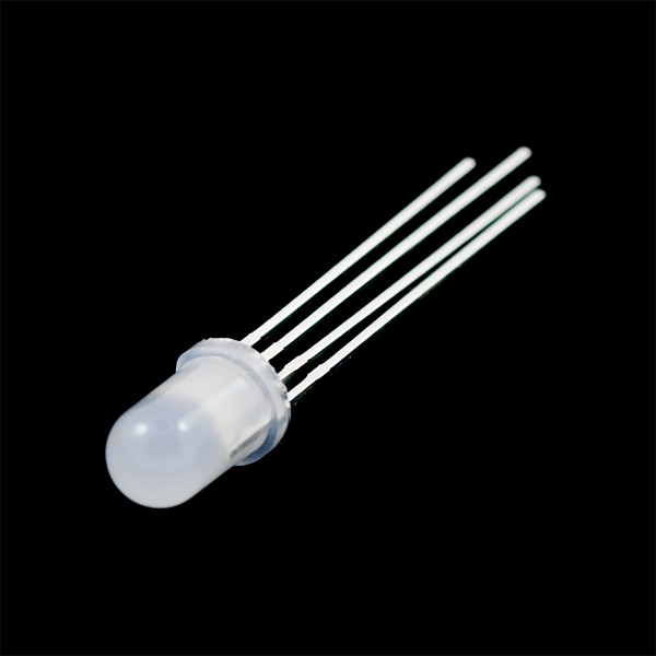
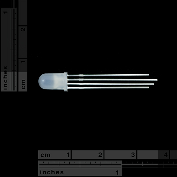
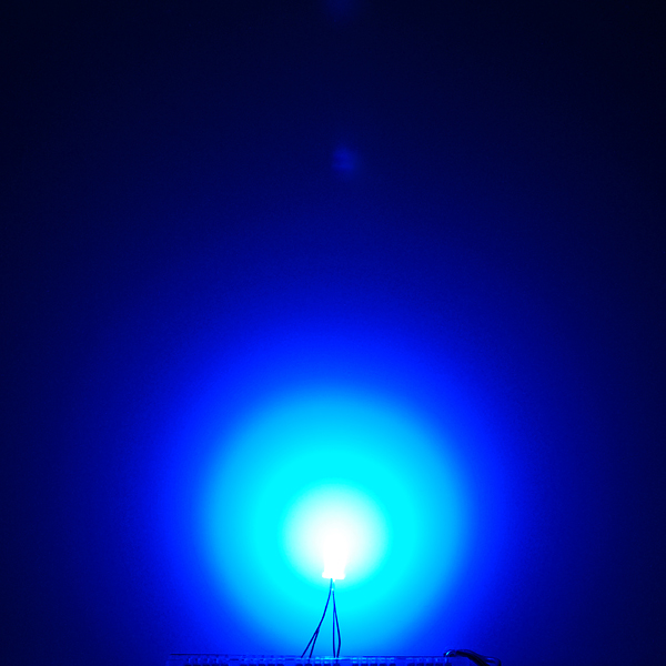
- LED - RGB Diffused Common Anode

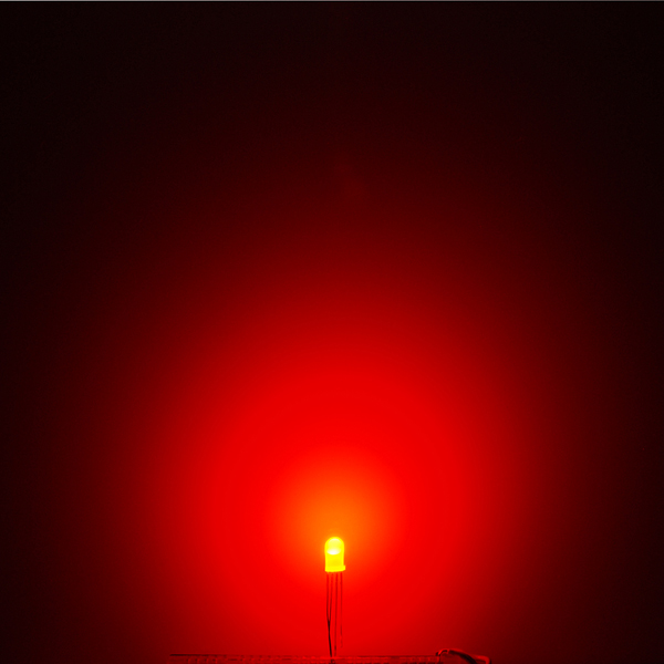
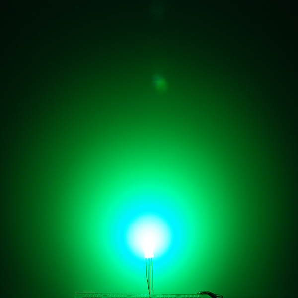
Ever hear of a thing called RGB? Red, Green, Blue? How about an RGB LED? These 5mm units have four pins: one for each color and a common anode. Use this one LED for three status indicators or pulse width modulate all three and get mixed colors!
These LEDs are diffused; so they'll appear dimmer, but have a wider viewing angle.
Note: The datasheet below is for the common cathode version of these LEDs, all of the values are the same except that instead of sharing a cathode, these share an anode. An updated datasheet will be added as soon as possible.
- Forward Voltage (RGB): (2.0, 3.2, 3.2)V
- Max Forward Current (RGB): (20, 20, 20)mA
- Max Luminosity (RGB): (2800, 6500, 1200)mcd
LED - RGB Diffused Common Anode Product Help and Resources
Non-Addressable RGB LED Strip Hookup Guide
February 19, 2020
Add color to your projects with non-addressable LED strips! These are perfect if you want to control and power the entire strip with one color for your props, car, fish tank, room, wall, or perhaps under cabinet lighting in your home.
Luminosity
The datasheet is for the LED circuit and does not include the diffused cover on the LED. So the luminosity under features is correct.
Core Skill: Electrical Prototyping
If it requires power, you need to know how much, what all the pins do, and how to hook it up. You may need to reference datasheets, schematics, and know the ins and outs of electronics.
Skill Level: Competent - You will be required to reference a datasheet or schematic to know how to use a component. Your knowledge of a datasheet will only require basic features like power requirements, pinouts, or communications type. Also, you may need a power supply that?s greater than 12V or more than 1A worth of current.
See all skill levels
Comments
Looking for answers to technical questions?
We welcome your comments and suggestions below. However, if you are looking for solutions to technical questions please see our Technical Assistance page.
Customer Reviews
No reviews yet.
The datasheet does show a common anode configuration. The note about it being a common cathode version should be removed.
I was wondering, where does Sparkfun get these from? I can't seem to find anything about the manufacturer in the datasheet, and I'm designing a kit that uses these. Any help?
The manufacturer information is right at the top of the datasheet; China Young Sun Technology Co., Ltd. www.100LED.com . Their site is currently not responding, though. Might be a good idea to look for alternatives :)
The SparkFun Library has now been updated as of 2/2/2013 for this through hole tricolor LED. You can find it under “LED-RGB-THRU” or “LED-RGB-CA-THRU” depending on the package under SparkFun-LED.lbr. If you are using the common anode you can find it under “LED-RGB-CC-THRU.”
To download the latest libraries just go to Github => https://github.com/sparkfun/SparkFun-Eagle-Libraries
Is this library correct? The Pads are touching each other and it fails DRC due to overlap.
Sorry for the delay in response but the alert was sent to my other e-mail address.
I talked to the engineer a while back that created the package and he recommended that you change the DRC rules for the pads on the board. We thought it was strange that we needed to change DRC Rules but the board worked after we changed it. Under the Restring tab, you would need to change the minimum pad for the top, inner, and bottom to 0mil. You should also change the to 15% or lower. After changing those settings, it passed the rules.
The engineer I talked to also recommended having the percentage as 10% or lower but my eagle board worked fine with 15%. I am unsure the of how this affects the fabrication of your board.
The part appears to be 'correct'. If the pads overlap it's because your minimum 'restring' setting in the DRC is too large. However, setting it low enough may cause other errors to be thrown up at the fab house.
A common way to deal with these types of PTH parts with relatively fine pitch is by offsetting the pads alternatingly. There was a led-tricolor-pth_special in the old library that shows that sort of construction, but you might as well just modify this one.
Note that if this is for some manner of automated fabrication, you might want to explore a different LED (either with pins bent outward by default, or piranhas, or SMD part, etc.)
This is odd, I must be running into some kind of Eagle bug or do not have something configured correctly... When I open the library, the footprint for the part looks good, no overlap of the solder pads and there is visible space between them. When in the schematic editor, I select the part using the "Add" function, the footprint has large pads that touch each other and causes the DRC errors. Weird...
OK, figured it out... In the DRC rules, I changed the restring setting MIN to 4mm and 10% and it looks like it should. I guess it is another one of those stupid Eagle "features", where the Design rule checker actually CHANGES the design.
correct - though in Eagle's defense, it's not just a DRC - it's the design rules. It would be nice if it would at least warn you about changes when adding a package, regardless, but alas.
The wiring diagram is also for a common cathode configuration. So change GND to +5V and invert the PWM signal to drive this common anode LED.