- Home
- Product Categories
- WiFi
- RN-XV WiFly Module - Wire Antenna

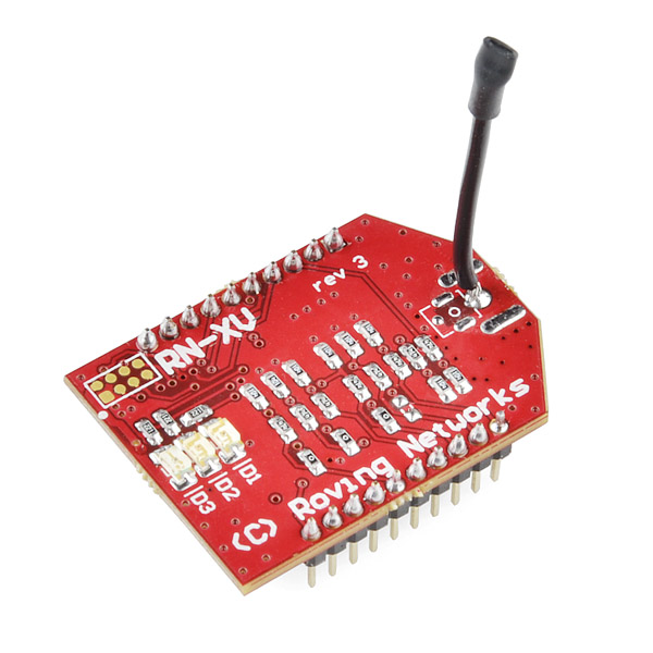
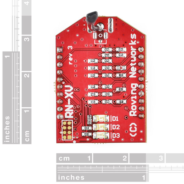
RN-XV WiFly Module - Wire Antenna
The RN-XV module by Roving Networks is a certified Wi-Fi solution especially designed for customer who want to migrate their existing 802.15.4 architecture to a standard TCP/IP based platform without having to redesign their existing hardware. In other words, if your project is set up for XBee and you want to move it to a standard WiFi network, you can drop this in the same socket without any other new hardware.
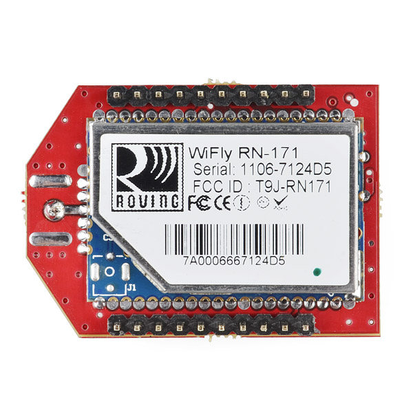
The RN-XV module is based upon Roving Networks' robust RN-171 Wi-Fi module and incorporates 802.11 b/g radio, 32 bit processor, TCP/IP stack, real-time clock, crypto accelerator, power management unit and analog sensor interface.The module is pre-loaded with Roving firmware to simplify integration and minimize development time of your application. In the simplest configuration, the hardware only requires four connections (PWR, TX, RX and GND) to create a wireless data connection.
- Based on common 802.15.4 XBee footprint
- Ultra low power: 4uA sleep mode, 38mA active
- Onboard TCP/IP stack includes DHCP, UDP, DNS, ARP, ICMP, HTTP client, FTP client and TCP
- Firmware configurable transmit power: 0dBm to 12dBm
- Hardware interfaces:TTL UART
- Host data rate up to 464Kbps over UART
- Supports Adhoc and infrastructure networking
- 8 general purpose digital I/O
- 3 analog sensor inputs
- Real-time clock for time-stamping, auto-sleep, and auto-wakeup modes
- Accepts 3.3VDC regulated power supply
- Wire antenna
RN-XV WiFly Module - Wire Antenna Product Help and Resources
Firmware updates
The problem: Microchip bought Roving networks and the FTP server your modules firmware is trying to reach no longer exists. We have a procedure to fix this this though. First, reset your module to the factory defaults:
factory RESET
Now connect to your Wlan:
set wlan ssid *your SSID*
set wlan passphrase *your WiFi password*
save
reboot
Now re-connect to your wlan and configure the new FTP settings: (We had to try the update twice to get it to work)
set ftp address 0
set dns backup rn.microchip.com
save ftp
update
You should see something like this:
<2.31> ftp update <2.31> FTP connecting to 198.175.253.161 FTP file=34 ………………………………………………………….. FTP OK. UPDATE OK
Now send:
save
factory RESET
reboot
At this point you will need to re-enter your SSID and pass phrase and re connect to your wlan. After you’ve done that, try pinging google to make sure you’re live.
ping dgoogle.com 4
(you have to add the “d” to the beginning of the hostname in order for the module to do a DNS lookup.) You should see something like this:
Ping try (len=32) 74.125.225.192 <4.41> PING reply from 74.125.225.192 PING reply from 74.125.225.192 PING reply from 74.125.225.192 PING reply from 74.125.225.192
That should get you going!
Core Skill: Electrical Prototyping
If it requires power, you need to know how much, what all the pins do, and how to hook it up. You may need to reference datasheets, schematics, and know the ins and outs of electronics.
Skill Level: Rookie - You may be required to know a bit more about the component, such as orientation, or how to hook it up, in addition to power requirements. You will need to understand polarized components.
See all skill levels
Comments
Looking for answers to technical questions?
We welcome your comments and suggestions below. However, if you are looking for solutions to technical questions please see our Technical Assistance page.
Customer Reviews
3.8 out of 5
Based on 8 ratings:
1 of 1 found this helpful:
Better options available.
If you're trying to replace an XBee-based solution - or you already have all of the XBee support hardware you want - this is a pretty solid option.
It is not 5V tolerant, and the sensor lines are only rated for 1.5V, so it's not necessarily trivial to add this in to an existing project.
The onboard configuration options are great - the v4 firmware is possibly useful without another microcontroller for certain logging applications. Getting it on to local WiFi is pretty easy.
There's no SSL/HTTPS support and I can't find a firmware SDK.
Client mode worked really well, but using it as a server suffered from a few issues - sockets had to time out to close, drastically lowering throughput.
Well documented, great performance
I was astounded at the quality of this module for how cheap it is. The documentation is flawless, and I had no issues setting this up for my exact needs. It also performed incredibly well, even in a noisy PLC lab at my school where I was doing an industry project my robot was able to drive out the door, down the hallway, and into the grounds. If you need a cheap easy to use wifi module that will perform well, you can't do much better than this
works better than expected
I got a regulator for it so I can run 5 volts on the Io. Im amazed how much it can do. I.e. Build in web configuration. If u like to tinker like me, u will love this.
Mixed happiness
If this device is used through an existing WIFI router, it works very well. Communications is fast and reliable. On the other hand, if this device is used as an access point it generally does not work. Windows 7 PCs can connect to it, but the firmware will report CRASH and then reboot as soon as an attempt to send data occurs. Numerous reports of this are posted on the Internet, so this is not a problem that only I have observed. Microchip bought out Roving Networks, and does not actually seem interested in fixing this problem.
Sorry to hear about this issue. I wish there was more we could do to help.
LEDs too bright!
I'm using this with the LPC1768 mbed on the application board. I'll suggest increasing the LEDs' resistors from 220 Ohms to 1.5k or even 2.2k.
I have a few of these, mostly used as an alternative to Xbee devices on a sensor network when it's more convenient to use Wifi. They mostly work as advertised, but about half of them fail to "sleep" which makes them not that useful for battery operated applications. In theory you set up a configuration allowing "set sys sleep N" and the module should go into low power mode drawing <100uA until an event wakes it up (a character interrupt or a pin signal). Normally this works but a few of the modules I've tried draw 3-10mA in this state vs <100uA, and they're too expensive to keep buying new ones until I get one that works. Probably ESP8266 is a better direction to go in now unless you need the specific command set and pinout.
0 of 1 found this helpful:
Best WI FI they cover all my needs thanks
Great Communications Interface Module
The RN-XV board with wire antenna performs well. My only recommendation for improvement of the board itself: The 20 male pins should be spaced wider apart to make it breadboard friendly, and should be extended long on BOTH sides of the board to allow easy wire connections from either/both sides of the board. The RN-171 software should allow the user to specify the path for saving the boot parameter file, and when in data mode, serially communicating with a 'dumb' controller that only understands specific commands, there should be a way to supress the OPEN and CLOS messages so the attached controller recieves only the data it expects. I have not tried the 'set comm open 0' and the 'set comm close 0' RN-171 boot parameters yet, but it looks like that may be what is needed to supress the OPEN and CLOS messages for a telnet session. Will test later and repost. Also need a way to supress the HTML header data recieved from a host server to that only the <BODY> content of the HTML response is sent to a device attached to the RN-171 serial output pin. Update: 9/27/18: Using Command mode($$$) and entering 'set comm open 0' and 'set comm close 0' prevents the output of OPEN and CLOS messages respectively. This helps resolve the issue mentioned above. Now, if we could just have more control over the serial output of selective parts of the HTML response recieved when using the web interface we could reduce parts count in many designs. The reason being, we may be able to eliminate the microcontroller required between the RN171 and a motor controller. The web server on a remote PC or MAC can easily provide the appropriate commands directly to a motor controller from the serial output of the RN171. This could also be accomplished using a websocket interface (ws: or wss:) with javascript as an alternative. Thanks, Bob Brinkoetter Senior System Engineer, retired
Nice! Even NTP is implemented... should advertise the feature too!
Two words. Xbee Killer.
No kidding. That's something I'd want if I was looking for a module to stick into a network-enabled thermostat.
sweeeeeeeeet! after much head scratching, i was able to get this thing to work. couldn't connect via serial, i kept getting "Auto-Assoc...FAILED" message. and no matter how i tried to send $$$, it wouldn't go into CMD mode.
however these steps worked:
In addition to GND, 3.3V, TX, RX, also connect PIO9 (pin 8) to 3.3V
Recycle power, since PIO9 is high, it goes into ADHOC mode
Connect to the "WiFly" ssid from my laptop
Telnet to the IPAddress 169.254.1.1:2000 You should now see HELLO on your telnet screen
Type $$$ You shold now see CMD on your telnet screen
Perform the commands:
set wlan phrase YOUR_PASS_PHRASE
set wlan ssid YOUR_SSID
save
reboot
when i did this each letter showed up twice as i typed, but didn't seem to matter
When it rebooted, i lost the connection, but since my CoolTerm window was open, i noticed the RN-XV automatically connected to specified SSID and got an ip. My laptop jumped back to my usual wifi network as well
I telnet to that new IP
It should again say HELLO, Again type $$$ and again it says CMD.
Now type "ftp u" and the firmware update is performed.
Now on startup, the RN-XV auto connects to my network and the green light blinks slowly.
many thanks to Virgil_Disgr4ce, would have taken me much longer without your article.
I had a similar problem when I bricked my module when updating the firmware. I found this solution though:
http://www.microchip.com/forums/m786903.aspx
----from post #5------------
It is not so easy but there is a procedure to regain factory reset with IO toggling GPIO9 I did it on my RN-171-EK using the 2 buttons but I had to retry many times. You hold down the GPIO9 while pushing reset and then release reset. After waiting a little more than One second, you press (toggle GPIO9) and you do this several times (more than 5) . Repeat this 5 to 10 times and you should eventually see some message coming back at original speed (9600). I has a similar issue when playing with FW updates. I tried to go down from v4.41 to V4.00 and I blocked the module. It would not respond to any command . After several trials it eventually spitted out again some message at 9600 bauds
by the way, i'm still not sure why i still can't get into CMD mode over serial by sending $$$. if anyone has any ideas, please do reply.
wow... ok... should have read Zacken's comment above more closely. the RN-XV does NOT play well with xbee explorer regulated. seems like people have had trouble with the xbee sheild as well.
i got rid of the explorer and hooked up 3.3V, GND, RX, TX directly to the RN-XV, and its working much better. i was a little worried that an unregulated RX, TX signal would damage the device but it appears to not have a problem with it.
SparkFun, could you please adjust the product description - it's not compatible with all xbee adapters. i'm going to order the xbee breakout board which i think is most suitable for this. http://www.sparkfun.com/products/8276
Can you confirm?
The XBee Explorer Regulated and XBee shield both depend on the onboard diode to do levelshifting for the Din pin. This method requires a pull-up resistor on Din. Series 1 and Series 2 XBees have a pull-up resistor enabled by default and the 900MHz modules have an internal pull-up that you have to configure (but its there). The RX-XV modules do not have an internal pull-up resistor, meaning you will need to add an external one (a 10k resistor between the Din pin of the RN-XV and VCC will work).
Can you explain most detailed this solution, because i connect a pull up resistor (10k)on the Din pin of the explorer regulated and this not work... the wifly is not receiving data from the uart however he can send to the uart any comments or suggest is well recived
The Din pin on the board and the Din pin of the RN-XV are not the same. There is actually a diode inbetween them. You actually need to connect to the Din pin of the RN-XV by soldering the other end of the resistor to the header pins.
Also, the current of the XBee Explorer Regulated and the XBee Shield use a much better level shifting method meaning that they work with the RN-XVs with no modifications
I have tried a 47K pull resistor and i still cannot get a connection. The signal I have with the resistor is 2.32V High and 1.56V low on DIN on the RN-XV headers pin3. Looking at the RN-171 data sheet is specifies a VIL Max as 1.0V for data pins. Would a 47M pull-up resistor be better and help lower to low. I am driving the DIN pin on the board with 5.12V to 1.12V signal.
Also confusingly the the RN-VX datasheet (see http://www.rovingnetworks.com/products/RN171XV ) says it is TTL UART, which would imply 5V VIH Max, but i cannot confirm the VIL/VIH from the data sheet.
its probably noise from the cheap switcher that is screwing things up. (unconfirmed comment of course)
Worth noting in the Features above:
Secure WiFi authentication: WEP, WPA-PSK (TKIP), WPA2-PSK
FYI - New 4.x firmware available: http://www.rovingnetworks.com/Current_Firmware I haven't tried it myself yet, but will this weekend..
I've been playing with this module and in my project I happen to be using Ruby. I wrote a small Ruby gem that can talk to this module, in case anyone else wants to use it.
https://github.com/unclebilly/wifly
Has anyone been successful in driving the power usage of this module down to the specified 4uA sleep mode? I can get the module to sleep, but it continues to draw 0.4mA.
I also had this experience and asked Microchip.
This is their answer:
By default, wiring the module with VCC, GND, TXD and RXD the sleep command will cause the current to drop down to around 330uA.
To lower the power, GPIO4, 5, 6, 7, 8 need a 100k pull down. The resistors on board are not pull downs. They are used for setting the pinout configuration. Other than this as long as the UART IO lines are kept low in sleep mode the current consumption should be low too.
I connected my unused outputs GPIO-5, 7 and 8 (4 is green led) directly to groud, and measure 3,6 uA in sleep mode.
Does anybody know what the ftp IP is for updating the firmware. I need to update to 2.45 but the IP isn't working. Apparently they keep changing it.
follow this guide but use ftp update wifly7-245.img instead of the one suggested
http://www.rovingnetworks.com/FAQs/I_get_FTP_Error_530_Login_Authentication_failed_when_I_try_to_upgrade_my_WiFly_module
You MUST see an assigned IP address when you join the network or this will never work. I did 10 board this way at my public library. My work wireless was too secure. I used a Sparkfun Xbee USB breakout board, TerraTerm and that was it.
According to http://serialio.com/support/WiSnap/QuickSettings1.php set ftp address 0 set dns name rn.microchip.com ftp update wifly_EZX.img // For adhoc ftp update wifly_EZX-AP.img // For newer sel AP
If it cannot find the file then try: set ftp filename wifly-EZX.img ftp update set ftp filename wifly-EZX-AP.img ftp update
Use ls command to see the downloaded images.
Is there any way to get this module working in monitor mode? If not can anyone recommend another similar module that can?
I think I might've bricked mine...
I tried to use the Arduino bootloader over wifi, (avrdude supports TCP, apparently), and the programming did not complete (it says the AVR was initialized, but then stopped). Now, all I get is a solid red LED on the RN-XV, and WPS-APP V1.231 on serial. After looking at the manual, it does not specify what this means. I cannot get into configuration over serial, and it never connects to wifi. I tried enabling WPS on my router, but nothing happened, it never tried to connect.
Anyone know how to fix the RN-XV?
I think I'm having the same issue. Did you ever figure out what to do?
Anyone have any ideas?
Yes, I contacted Roving Networks directly, and they're replacing it, they said it was definitely bricked.
Just wondering if you have received your repaired device? How long did it take for RN to respond to you?
I, too, have bricked my device within the first 2 hours of having it. For a device with as clean and simple an interface as this device has, it seems like it should be bullet proof from such fatal errors.
RN has been extremely slow to respond with very vague answers on when they will even get me an RMA number let alone a repair.
Just wondering how your experience has been.
They took about a week to get me an RMA number. I just mailed it a few days ago, so I haven't gotten it back yet (also shipping from Canada, which never helps)
This is frustrating - I'd love to buy an RN-XV WiFly Module for Christmas to interface with my Arduino Uno for a project in my car that will be controlled via my iPhone, but I've read so many things that say 2 way communication is difficult due to logic level conversion problems with BOB-08745. So I was considering BOB-10403 instead.
1)Does anyone have any experience using BOB-10403 with a RN-XV WiFly Module and an Uno? Is it fully capable of bi-directional logic conversion between the Uno and the RN-XV?
2)Are there any shields for the RN-XV WiFly Module that will work as expected and do the voltage and logic conversion for me? That would be my ideal device, but even the shields have issues.
Why is this so complicated?
I'd appreciate any help.
When is this item going to be back in stock?
Is there any chance that these will be offered with U.Fl. as well as the wire antenna once they return to stock?
We also carry them here.
They are offered with uFL; see http://www.rovingnetworks.com/products/RN_XV and click the 'buy now' tab. The part number is RN-XV-U.
This is a great little WiFi. Needed to INVERT the RS232, but now works like a charm. Using the AdHoc mode, I ran 3.3 volt power, held the AdHoc line HIGH, run the RX,TX to a PIC 12Fxxx and out to my USB/RS232 dongle and in ten minutes, I was sending data and commands from my iPhone. Starting to write an iPhone/Android app to automate the process.
@OdeMae, My wifi module adhoc mode on, my windows xp pc find my module, but my phones are android and windows phone 7 not find my wifi module, how did you fix it ? your comment: ( @OdeMae Starting to write an iPhone/Android )
I could not get adhoc to work from by android phone, gave up and used access point
User manual says this supports WEP and WPA security so you could likely use it on your existing secure home network.
Things were going great for WiFly and I until today. I use WiFly on the SparkFun RedBot. Way better than XBee for me since I am using Python on my computer which talks directly to WiFly via socket connection (see pymata-aio for more there). Anyway RedBot uses 3.3V on the power rail but the Rx and Tx connect straight to the WiFly's Tx and Rx. So there is a 5v concern on Arduino's 5v Tx to WiFly's Rx. It actually has worked for a few weeks on the XBee HW Serial option. No problems! I'm getting lucky I guess. But for only 1 day I used the XBee SW Serial option on the RedBot and that equaled WiFly death within an hour. :( Any thoughts why the RedBot 5v lines from the HW Tx was fine, but the SoftwareSerial Tx was 5 volts of death? I looked at the RedBot schematic: https://cdn.sparkfun.com/datasheets/Robotics/RedBot_v12.pdf and honestly I'm not sure why SoftwareSerial was death to my WiFly, but HW serial has been fine for weeks. Any thoughts? Did I just get unlucky or will the new WiFly I ordered last an hour too? :) I can just stick with HW serial, but I'd like to use SW serial for WiFly setup.
So SparkFun I'd love to get a 5v tolerant version of this board. It's absolutely the perfect match for RedBot if you are using Python or another program that can make a simple TCP socket connection. LOVE to use it with more confidence on RedBot rather than hoping 5v coming in to Rx survives the day. :)
Does anyone know any library available for using Teensy 3.1 talk to this WiFly module?
The free app pfodWifiConfig lets you easily configure RN WiFly to connect to any network and also set other device parameters like Sever listen port or client host and loging example sketch and supporting libraries are available from http://www.forward.com.au/pfod/pfodWifiConfig/RN_WiFly/pfodWifiConfig_WiFly.html
The library handles all the $$$ CMD stuff for your and the free Android app provides a user friendly interface.
RN-XV WiFly Module - Wire Antenna is a new product in the market and it seems that this product is likely to give a competition to other protocol users. The only shortcoming is that it is a wired one. Get more information on generic Viagra online (http://www.pharmacyglobalrx.net) so as cure men's Impotence
I can’t send any comment to the browser….. Everything seems to be ok: 1. The server AP is already started. (open, ip: 1.2.3.4:80, ……) (ARduino Uno+ArduWirelessSDshield+RovingRN171) 2. I can join the AP created for the Roving RN-171 with my MacAir (the ssid appears ok in my Air wifi list). 3. When I type http://1.2.3.4:80 in my browser, the Serial Monitor shows the connection, with the message whole right message blablabla…..keep alive…. 4. But the browser shows only waiting for 1.2.3.4 or…..starts downloading something and remains like this…… 5. The arduino script is very simple, I just want to write something in the browser…
include <SPI.h> include “WiFly.h” WiFlyServer server(80);/ void setup() { WiFly.begin();//begin WiFly communictaiosn server.begin(); //initialize the server
} /////////////////////////////////////////////////////////////////// void loop() { WiFlyClient client = server.available(); if (client) { while (client.connected()) { if (client.available()) { client.println(“HTTP/1.1 200 OK”); client.println(“Content-Type: text/html”); delay(1000);//delay is very important client.flush(); // client.stop(); } } } }
I suppose I am really close to the final solution, but there is something that still fails…. :-(
Any idea?
many thanks
It's not easy to configure. Here is a setting tool. www.tinyosshop.com/datasheet/WiFiBee%20setting%20tool.rar It will help many people :)
Does anybody make it work with Arduino?
I was able to connect and once i did the firmware upgrade, i am not able to connect anymore. I can see the WiFly-EZX-ff wireless ap but when connected i get Limited Access and no ip. Can any one please help. I am using RN XV 171, MEGA and Wifi/Xbee-SD Shield for the above. Thanks in advance - rakesh.salian@gmail.com
Just thought I'd let everyone know that these modules don't work as advertised. There are numerous firmware issues with the 4.xx series update and Microchip isn't responding to user submitted bug reports. I contacted them over a year ago reporting issues with the firmware and got no response. That was version 2.32 of the firmware. I resubmitted my bug report in late December and got a "let me check with the developers" response. After another month of back-and-forth, my bug report is inexplicably closed and the firmware is not fixed.
Among the issues noted: - module spontaneously resets for no reason - loss of all settings after spontaneous reboot - UDP broadcast of GPIO states is non functional - Loss of TCP connection state causes remote connection errors until the session times out
In short, these modules are beyond unreliable. I would not recommend these as a solution in any project and Microchip doesn't seem to care.
Question. So, I'm using this item on an X-Bee Board from Adafruit (http://www.adafruit.com/products/126), which in turn is hooked up to the Sparkfun basic FTDI cable breakout.
My wireless credentials recently changed, and I can't command line into the wifly. Its just stuck in a loop of looking for a wireless network that doesn't exist. eg: "Auto-Assoc…FAILED" etc. I can't telnet into it either because its too busy and it time out. Everything says set the PI09 to high to create an ADHOC network so you can reboot it.
How do you do that on a explorer or the adafruit board? Or do I have to go hooking jumpers into things, and wire it to an arduino, etc.
I'm sorry if this a dumb question, I'm just stuck.
The issue is with command termination. When you send $$$ to get into command mode, you must not follow that sequence with a carriage return or line feed. It's in the data sheet. I use cutecom on a linux laptop and can turn off line endings to get to command mode, but then I have to turn them back on to actually change the settings. It's annoying that it works that way.
Since Roving Networks was bought by microchip, a lot of the information in the user manual has changed. Here is a link to the latest manual. http://ww1.microchip.com/downloads/en/DeviceDoc/rn-wiflycr-ug-v1.2r.pdf There are significant upgrades in the v4.00 firmware as well, and the address for firmware upgrades has changed.
There is something confusing about sensor input. In datasheet, page 4 it is said "Pin 17, SENSOR 5, Sensor Interface, Analog input to module, (3.3V tolerant) " and User Manual, page 73 says "The WiFly-GSX has 8 analog sensor inputs that can be driven between 0 to 1.2VDC. ... Warning: Driving these inputs above 1.2V will cause permanent damage."
Does anyone knows which is correct and what's the max voltage on sensors 4-8?
Spark Fun needs to update the information about the RN-XV. The updated version has firmware 4.0 which by default uses the new Soft AP. The new user manual is on microchip website.
Well, I am new to this stuff.... It took me days to just get a serial connection going. For you other newbies, if you are looking to just start off with a simple serial connection go to the Sparkfun forum and see this post.
Is it possible to do peer to peer communication using ad-hoc network? I mean one RN-XV talking to another. Something like this... COM port -> RN-XV -> (Peer2peer/Ad-Hoc connection) -> RN-XV -> COM port
Hello!
Does any of you know the difference and limitations between this module and this other:
http://www.digi.com/products/wireless-wired-embedded-solutions/zigbee-rf-modules/point-multipoint-rfmodules/xbee-wi-fi#overview
Is the lack of a TCP/IP stack very important?
Hi Folks,
I am interested in one of these but all I see is endless issues trying to set these up. Has this been resolved?
I would like to be able to set the WiFly module up via USB so I assume I would need a XBee explorer module to do this?
Anyway would be interested in finding out if the setup issues have been resolved and what exactly I would need and and what is the setup procedure is?
Also are the unit loaded with version 4.0 firmware?
Thanks and regards,
Ian
Can I use this module as a repeater?
I use this modules for home automation and alarm purposes. In the past I used Z-Wave and XBee, but now I changed to Wifly because these modules are so easy to use and operate very reliable. Because it is just Wifi, you can use all the tools you are used to.
If you are interested, I created a completely wireless motion sensor with this module. It uses a 1 cel Lipo battery together with the LiPower - Boost Converter for a solid power source. http://tony-wifly.nl-web.com/ (MotionSensor.pdf)
For anyone attempting to update the firmware on this module, but getting a "timeout=2" error, I posted the solution that worked for me on my blog: http://www.mostthingsweb.com/2013/07/solving-the-timeout2-error-when-updating-wifly-firmware/. Not sure if SparkFun is shipping these with the latest (4.0) firmware, but I got mine a while ago so it needed a update.
Hello all,
Just a quick question. Can we combine this module with the XBee Explorer Regulated board (WRL-11373)? I think we can, but I am asking just to be on the safe side…
thx
Before you RTFM, visit the site and download the latest PDF. The link above is out of date (2011) and there have been changes.
Also, I can confirm that the current releases of the XBee Explorer Regulated work well with this module.
hello
my question is that can we communicate between two rn xv and a laptop or pc ??? if so then how? plz help
i m having problem when communicating between rn xv module and microcontroller (atmega16).my module recieves sometime correct information and some times it loses data what i should do ?
is there any arduino fio wifly project examples out there to start looking at
Would it be possible to communicate to one of these modules from an Android phone with Wi-Fi Direct? In the Wi-Fi Direct FAQs, it states that Wi-Fi Direct is backwards compatible with existing Wi-Fi devices.
Yes it is. See http://sailboatinstruments.blogspot.ca/2012/10/talking-to-android-phone-through-wi-fi.html
We are facing a couple of issues while trying to call a web service using this product. The responses are both truncated and contain a lot of unreadable characters. Please see details below. Any suggestions?
jÔ: ?-Cmd
AOK Auto-Assoc Smood chan=1 mode=WPA2 SCAN OK Joining Smood now.. AssociateDHCP in 3000ms, lease=3600s IF=UP DHCP=ON IP=192.16 EXIT CMD Ú´Ã…
AOK
AOK
AOK
AOK Connect to 198.105.251.46:80 OPEN
The formatting of the log file wasnt how I intended. But stated simply, Ú´Ã… in the log is an example of unreadable characters. While IP=192.16 is an example of truncated response. You all seem to have worked on this for a while. Hopefully, someone has a better handle than us.
I have put up this tutorial in how I configured this module using FioV3 or via adhoc network http://www.forward.com.au/pfod/ArduinoProgramming/FioV3/index.html
iPhone support.
Just a note for those looking for a simple iPhone to Wifly link app solution. I have made an iPhone transmit app that sends simple ASCII string commands to a Wifly radio, for robotics remote control applications. It's Star Wars themed (since it's for controlling an R2-D2 robot!), but since you can customize the button labels and command strings, you could use it for other applications or for quick testing. This is send only. It's on the app store, called "R2 Touch". Link below: https://itunes.apple.com/WebObjects/MZStore.woa/wa/viewSoftware?id=631960765&mt=8#
On my web site (www.curiousmarc.com) there is also an example configuration of the Wifly for creating an ad-hoc network for the iPhone to connect to, which was actually the difficult thing to figure out.
There is also another more generic iPhone test Wifly app that lets you send data from a console-style interface. This one sends and receives, and also discovers nearby Wiflys from their UDP broadcast. It's called WiFlyClient, made by the Wifly manufacturer Roving Networks.
Is there any hope that there will be a library for this at any point in time? Or maybe some documentation relevant to Arduino?
I'm having a strange behavior with this module. When it turns on all LEDs are blinking, then after 3-5 seconds green LED goes dark solid. I'm unable to enter in config mode (with $$$ via command line) or establish connection. This happened absolutely spontaneously. I'm afraid it's bricked somehow... Had anyone something like this? Thanks for help.
Dear, to configure my RN-171 through the commands (set), then a REBOOT and module erased general, and now it connects to the serial port, it does not come more in command mode ($ $ $), showing only version firmware and MAC address. I think it must have corrupted the boot. Does anyone have idea to circumvent the problem?
Thank you!
I bought this chip before either of the antennae versions came out... Is it possible to solder an RP-SMA connector onto this chip?
Got my RN-XV... was able to connect in AdHoc, configure it to my WiFi Network just fine. It now sits there flashing green every second. I can easily telnet to it from my Win7 machine using telnet, but whenever I telnet from my iMac, it connects, but does not echo any characters ...
Anyone else having issues with telnet from max ( 10.6.8 ) to RN-XV ( 2.32 fw ) .. It connects, and the amber led flashes when I type, but no characters are echoed back to the mac.
don't think RN-XV echos chars, perhaps you have local echo turned on in window's telnet.
I've had one of these for about a year. Recently updated the firmware. My frustration is that I no longer can get it to work with a FIO (blue). It works fine via a FTDI-USB cable - it attaches to my WiFi network and works as expected. However, as soon as I plug it into a FIO (even one with basically a null program) it will no longer attach to the WiFi network. The two "played together" very well 9 months ago. Any thoughts would be greatly appreciated.
(update 20130218) I just ordered a new FIO (red), a new radio, and a XBee breakout board to get to the bottom of this. Don't feel I should have to make this further investment, but I need to figure out how to move forward!
Late breaking news, when I powered the FIO via a LiPo battery, the WiFly worked just fine. So...in a way this is good news...I think.
I've problem with this module and arduino fio. when i put module to arduino, arduino is reset not working. XBee modul work fine. Can You help me?
I'm having the same problem (see next note). If you have any success, PLEASE share it. What's frustrating is that this module worked in the same FIO last Spring. I'm now wondering if the newer firmware (2.38.3) is the problem.
Reading Sensor output?
Sample Documentation shows this below:
The resulting string sent to the server is: GET /userprog.php?DATA=0F3000001111222233334444555566667777\n\n The data format for this example is: 2 Bytes GPIO Channel 0 Channel 1 Channel 2 Channel 3 Channel 4 Channel 5 Channel 6 Channel 7 0F30 0000 1111 2222 3333 4444 5555 6666 7777
Please help me understand how I should read this in a c# application? I already have this data posting to my web server and able to read the value, but i am totally confused on how to read the data.
Does anyone have any comments on the 3V3 / 5V issue? Is this modele 5V tolerant to be connected directly to an Arduino without divider or logic level converter? I see a lot of people doing that.
Based on the datasheet (but it's not clear) and based on user reports - the WiFly is not 5V tolerant. Using 5V will, long or near term, lead to your WiFly burning out.
3.3V for the data pins, 1.5V for the sensor pins.
Is it possible to use this module as a web browser? I want to read data from a web server (an XML, weather for example) and display data on an LCD. thanks
What is it's range? also,can it work with the Netduino plus?
I'm slowly starting to think that this module is a piece of crap. I modified my energy monitor (http://antibore.wordpress.com/2012/03/05/monitoring-electricity-usage-at-home/) to use RN-XV instead of XBee. Initially I thought the setup is working fine and changes required to code were very minor and no hardware modifications needed. However I noticed that always after ~10 hours the module will freeze and stop accepting data. I tried to remedy this by issuing reboot command every hour or so, but that didn't really help much. As a last thing I modified the hardware so that RN-XV reset pin will be pulled low to reset it every hour. This seemed to work, but now after ~26 hours the module was frozen again. This time it's a little different though, all three lights are in pattern (1 on, 2 on, 3 on, then all off again and start from the beginning). Manual does not tell pretty much anything about the leds.
Curiously, every time the module gets frozen, it's still sending out something to the server. I use mac mini as a server and after the module freezes, mini starts to reboot because of kernel panics. The rebooting stops when I cut the power from the module. If I'd have time I'd like to investigate this with Wireshark and try to find the offending packets. Another thing is how the hell some network packet can crash mature kernel code. Reminds me of bad old Windows '95 times.
Suggestions are welcome is someone has any. Last thing that I can try is to rig the hardware to cut the power to the module periodically or just give up with this and change the module.
Perhaps using a transistor as a switch to use a periodic signal (Perhaps once every hour or two) from the microcontroller to cut the power for a few seconds and then switch it back on, allowing the module to reboot rather than use the reset pin?
(Hope this isn't a stupid suggestion - I'm kinda new to this stuff...)
Agreed! I have been working over a month now to get this shield working with the library examples and it's still not working. HATE IT!
I've been working with the RN-XV for a few weeks building a WiFi Garage Door Opener (cool project) and I got to say it's been nothing but a struggle using this module. Why - because the documentation sucks! The RN-XV data sheet doesn't even show the three status LED's, it's just incomplete! Basically they took the RN171 and put an IP stack on it and renamed it the RN-XV but there are other subtle changes as well and many inconsistencies. So you really need three documents to try to understand what's going on (RN-XV Datasheet, RN-171 Data Sheet, WiFLY User Manual & Command reference) plus a lot of on-line research.
IMO they need to complete re-write the GPIO and Analog sections so they make more sense. The implementation could be easier too, having the deal with the bit masks and reference that to actual pins could have been done better. In fact they use 0 for input and 1 for output... why not O=0, I-1 like the PIC? Another grip I have is there is no command reference table or summary. You need to scroll through pages and pages to find what your looking for.
So I did finally understand and get all my GPIO working, and then wanted to use an analog sensor pin for a TMP36 temp sensor and hit another brick wall. The documentation is SO POOR on this part that your lucky if you have a clue to what's going on. After much research on this I finally found the best answers here on this forum. This might help anyone wanting to use these analog sensor pins. Now is this a cool device - YES Absolutely VERY COOL so let's hope that Microchip (assuming they acquired Roving Networks?) can get the documentation and examples up to a higher standard that make it more fun to work with!
Does LEDs have any pattern? I mean I connect my RN-XV to 5V, GND, TXT and RXT and when I power up first blink green then red, then green led is high for about 1 sec, then all over again??
Can some one help me distinguish the pin in wifly Rn 171 module. I am a beginner and found it hard to distinguish which pin represent what??
Just thought I'd mention that the default FTP server has moved:
http://rovingnetworks.com/FAQs/I_get_FTP_Error_530_Login_Authentication_failed_when_I_try_to_upgrade_my_WiFly_module
Got to use
"set ftp address 208.109.14.133" and "save"
to use FTP update on the modules. Thought I'd post it here, so that others might not have to search like I did.
It has changed again.
follow this guide but use ftp update wifly7-245.img instead of the one suggested for RN-XV boards
http://www.rovingnetworks.com/FAQs/I_get_FTP_Error_530_Login_Authentication_failed_when_I_try_to_upgrade_my_WiFly_module
You MUST see an assigned IP address when you join the network or this will never work. I did 10 board this way at my public library. My work wireless was too secure. I used a Sparkfun Xbee USB breakout board, TerraTerm and that was it.
Anyone tried sending UDP to a broadcast address e.g. 192.168.1.255 ?
Ok, I'm now feeding it regulated 3.3 V, ground, and PIO9 to 3.3 V. The led is lit. Should I see the network SSID appearing (I don't...)?
It will be good to have a more comprehensive documentation on sending/recving UDP. The provided documentation is insufficient and deters potential developers.
Great product ! If anyone know how to connect the modules with the old Xbee Shield , just let me know, tks !
I always seem to get a read out of the same list of integers with the following pattern after connecting to the arduino and haveing the arduino set the module to command/config mode.
36 13 13 10 69 82 82 58 32 63 45 67 109 100 13 10 60 50 46 51 49 62 32 10 36 13 13 10 69 82 82 58 32 63 45 67 109 100 13 10 60 50 46 51 49 62 32 10 36 13 13 10 69 82 82 58 32 63 45 67 109 100 13 10 60 50 46 51 49 62 32 10
My code is as follows on this pastebin: http://pastebin.com/YUy3bm4x
Any help as to why I don't see ASCII characters?
Check the baud rate of your terminal. It's 9600 by default.
hi everyone. i just received my RN-XV. so i start to figure it out. I manage to connect my RN-XV to my android phone via wifi tethering. And i stuck there. what i really wanna do is,plug the rn-xv to my uC circuit. then connect the rn-xv through router, so i can access my uC circuit through any device such as phone, pc and etc. what is the configuration that i need to change?
I need to read analog input on RN-XV (3 analog sensor inputs). For testing, I grounded pin 20, submitted show q 0x1ff and was expecting to read a 0 volts value, but instead was unable to see any difference from leaving the pin open. Same happened with other sensor pins. even tried to change parameters. What am I doing wrong?
I have seen only one example of a correct analog reading and that guy was able to do that by modifying the resistors on board.
I also tried the same and I was unsuccessful. I tried several analog sensors, tried a direct DC output between (0-400mV) and couldn't get a correct reading also.
I would very much appreciate if there is a clear documentation with one single example for this case.
Is anyone else seeing this firmware crash with 2.32? I've posted it here: arduino.cc forums.
Basically if you attempt to open a TCP connection and it fails, then attempt two or three more connections that work the firmware crashes and the WiFly reboots. Here's my serial log of the crash: set ip host 192.168.1.42 AOK set ip remote 80 AOK open Connect FAILED
Hi Darran,
I get exactly the same behaviour on 2.32. I put in a bug report to Roving Networks, and they sent me a new version to test (2.33) but the error still occurred. Last message I got from them said that they can't reproduce the problem, but they do believe me when I say it exists.
I will be looking at the Gainspan module for future projects.
Regards, Dean
Cheers Dean. I'll give the arduino thread another week and then see if I can convince Roving Networks to fix the bug.
The GainSpan looks interesting, although it costs twice as much and is only 802.11b.
Firmware: 2.32 Test PC is connected via ethernet to WiFi AP.
I'm a bit stuck and hoping someone can tell me where I'm going wrong please.
I'm using a USB->Serial adapter connected to the RN-XV and my benchtop supply for 3V3. No worries with any of that.
Right now I just have TeraTerm connected to the RN-XV via serial and that works just fine. Connect to wlan, setup ssid/pass etc without problem.
I've used the "Product Training" pdf from the website and get stuck when attempting to set up a bi-directional connection with the PC. Just for reference, that's on page 36 of the training lab document.
The situation is that I'm able to open the connection on the device but I only get one way communications; from the RN-XV to the TT instance on the PC. I don't receive data back at the serial output of the RN-XV (even though moments before it indicated "OPEN". i.e. I have two instances of TeraTerm open. One on COMx talking to the RN-XV (to be replaced by uC eventually), and one using TCP on port 2000. This seemed like a good test setup to familiarise myself with the device.
So, I first thought this must be a firewall issue with outgoing data from my PC over the local network. I've added exceptions to the firewall for TeraTerm. I don't think this is an AP issue either... although not convinced.
I'm really stuck... Once the connection is open, anything I send to the RN-XV via serial is received by TT on port 2000. Anything entered on the same TT window is not received back at the RN-XV serial port.
According to the traing pdf I should expect to see bi-directional comms going at this point.
Any thoughts? Thanks!
Hello, I am currently working on a project intended to create interference on wifi channels (nothing illegal - it is for a university lab dealing with algorithms to switch channels automatically). We have this module and I was hoping someone could point me in the right direction to force the module to transmit packets on a specified channel.
thank you!
Umm, wouldn't you just set a channel, transmit a few packets, repeat for next channel (etc)?
Where are you stuck?
That's exactly what I want to do! I am stuck with the programming on the arduino end - I am fairly new to using arduinos. I figure I can use UDP, but I have only been able to use the command mode directly with the module - not autonomously.
I've written an Arduino library for the RN-XV. Version 0.1 is available here github/WiFlyHQ. At the moment it supports hardware and software serial interfaces, sending and recieving UDP packets, making TCP connections and sending and receiving data over the connection.
I plan to add support for all of the RN-XV features, but if you are interested in anything specific then post a request or comment on github and I'll work on that next.
Cheers.
Hi, I found the unit easy to set up, much more intuitive than xbee, as most of us are used to deal with wi-fi these days; xbee it's yet another wireless platform... I had problems when setting up sleep, the unit got almost unresponsive... but could work that around resetting it. One thing I'd like to ask to everyone is: xbee can work in a "mesh" which is interesting as it supposedly can relay messages using a string of xbees transparently (no dark spots)... Can that also be achieved using the WiFly RN-XV? Also just for the register Sparkfun didn't use foam in the pins, so some of them were quite bent, good they didn't break when I set them straight...
As I understand it, a standard (classic) Xbee can be used to download code to the arduino. Any idea if this product can do that (or if the new Xbee 2.4ghz can) ?
This product can, and it works, and someone on the forums has gotten it to work: http://forum.sparkfun.com/viewtopic.php?f=13&t=21326
It's identical to this post. However, I managed to brick my RN-XV while doing this, so I would advise against it.
I have a small ultrasonic pulser/receiver board which I connect to the FTDI chip breakout. Controlled by Processing.org sfw & FTDI driver. Has anyone simply attached this unit to it?
Here are a couple of posts I made outlining my experiences with the RN-XV. Hope people find them useful:
RN-XV Wifly
Arduino talks to Python
I am also trying to do exactly the same. My laptop hosts a php server and the WiFly reads a file on the server every second. But after few seconds (which is not fixed, completely random), the module stops receiving data and the green LED on the Wifly which normally blinks becomes solid. A hit-and-trial of adding delays at different positions in the code did improve the situation, but not much. Any idea what might be the problem ? Thanks.
I had the same experience. For me it was all caused by the breadboard. I guess it was causing RF interference. Once I pulled it off the board and attached via wires, it works great.
I love this device. I bought one a few weeks back, had no problems setting it up at all. I've written a short guide to setting it up without using a serial adapter, just getting it into ad-hoc mode here:
Setting up the WiFly RN-XV
Question: Can I use this 3.3v Wifi to communicate with an arduino that is powered by 5v? (obviously I wouldn't be able to power the wifly with 5v, but if they were each correctly powered (arduino with 5v and wifly with 3.3v) would they still be able to work together?
I have a system that is already built, and powered with 5v, and just want to add this module to it.
Use a converter else you smoke ur module, this translator too should work.
I had high hopes for this bit of kit but since buying it I've seen a few messages saying that the RN-XV + XBee Shield + Arduino Uno combo doesn't work without hacking at the hardware. Is this still true? I have wasted many hours looking for a solution and just need to know if I have to throw out the kit I've got and get something else.
I bought these modules because I have a specific wireless application that I need to build quickly and a breadboarded solution is not appropriate, nor do I want to have to modify the boards.
I have an Uno R3, and RN-XV Rev 3. Can these be made to co-exist without hacking hardware, and if not, please suggest which combination of Arduino Uno compatible modules are known to work?
Many thanks.
You can use the XBee breakout board. It def works. http://www.sparkfun.com/products/8276
i had trouble with the XBee explorer regulated and i hear the same issue happens with the xbee shield. OR checkout boulderjoe's instructable right above your post for a quick way to get your shield working.
Hey Robotechnobloke- As it ships it will not work with the Uno and Sparkfun XBee Shield. But you simply solder a jumper over the the diode and it works. You can see an example in this instructable. http://www.instructables.com/id/Visual-Network-Threat-Level-Indicator-v2/
I wasted a TON of time before I figured that out...
I just finished a project using the Arduino Uno, RN-XV WiFly and the Sparkfun XBee shield. You can check it out here: http://www.instructables.com/id/Visual-Network-Threat-Level-Indicator-v2/
We need more Wifly modules!!
They are here!
This little guy is awesome! Real easy to setup and connect with my Arduino. I used the xbee adapter from adafruit to connect it to my 5v project for simplicity. I did have wifi connectivity issues on the 2.30 image but was able to run the ftp update command to get version 2.31 which resolved all my problems. Currently using it with a pro mini(5v) in a clock project to keep the clock synced with a NTP server.
Hey Bertie do you know of a tutorial for connecting an arduino pro mini with a wifly module?
Hi! I would like to know if the RN-VX is compatible with the ArduinoXBee Communication Shield v1.1 (M. Yarza) and Arduino UNO? Or do I need an 3.3v regulator for the RN-XV? How can I make it work and uptate de RN-XV firm, it is possible with a Mac computer and all my hardware mentioned before? Thanx in advance to all.
Awesome product. Very easy to setup and use. I've only tried UDP so far but the TCP and HTTP support looks easy too.
I did have a problem when I updated to the 2.30 firmware - stopped associating with my Airport Extreme, but dropping back to 2.27 fixed the problem.
I'm using it with an xbee shield from seeedstudio that I had for zigbee experiments.
I also had trouble with 2.30 and an Apple Airport Extreme.
I ended up turning off authentication on the router to run a firmware update. It connected just fine and I ran the update to 2.31 and when I re-enabled the routers authentication and The RN-XV worked perfectly.
Had problems after updating to 2.30, stopped working with Apple Airport Extreme, would cycle connect/disconnect constantly. WiFly Ver 2.28, 09-08-2011 on RN-171 works just fine. Just reporting this here so anyone with similar problem can try the different version.
Nice module at a great price, plan on using these with the fio for low cost battery powered wifi projects.
Yup - 2.31 fixes the problem with airport extreme. This thing works great with the fio - and the two together are cheaper than just the wifly sheild. Go figure.
Yes RN knows about this and fixed it in 2.31
I tried to update the firmware, but it remains in 2.30... is 2.31 public yet?
It was available in BETA, they are releasing it to general release today
If you're planning on using the analog sensor pins you should note that the WiFly can only handle up to 1.2 volts, not 3.3. Seems like a logic level conversion is in order. But, you can set the WiFly to supply 1.2 reference voltage to a sensor power supply pin that could be applied to the low side of the converter. I suppose you could just use the 1.2 volt supply for some sensors but I think I'll get 3.3 from elsewhere to supply my sensors and translate the output. Reasonable?
Hello, i'm usign this module and i have some problems with the serial connection with a LPCxpresso 1768. The sent is corrupted, for example, send a number sequence 18576, 18577, 18578 and arrive to computer only 1857, 185 or 185718576 for example. The module is set to 9600 baud without flow control, AP mode and TCP mode (also tested with flow control, in UDP and ad hoc mode). When increase the baud rate, errors are more frequent. ¿Any suggestions? ¿Firmware update?
Thank you!
Hello,
is the hardware flow control working for you? In my wifly, RTS never goes HIGH.
Here's a new tutorial on setting up this module as a remote, internet-controlled switch:
http://log.liminastudio.com/itp/physical-computing/using-the-rn-xv-wifi-module-as-a-remote-switch
Hope it helps!
I have connected this device to my pc via an xbee explorer, which works okay. However, I am having trouble connecting thru telnet. I can not connect from my pc via telnet until I PING my pc from the WiFly. Then things are okay. Any ideas/suggestions on why this is happening and how to fix it?
I'm having trouble putting the device to sleep and waking it up.
Right now the unit is connected in AdHoc mode to my PC and commands are being sent from the PC (over telnet to port 2000) with the unit being powered by two AA cell batteries.
I've set the system IO mask to 0x20F0 (enable IO8 as input) and the system trigger to 0x20 (go to sleep on IO8 high), but powering the unit from 3.2V (battery) and then tieing IO8 to VCC does not put the unit to sleep.
I've also tried waking the unit up after putting it to sleep with a "sleep" command. I set the system trigger to 0x20 and set CTS (pin 16 to 3.2V (battery) and this does not wake the unit up. I have two IO lines availabe from the MCU and want to be able to put the unit to sleep and wake it up.
Has anyone done this? Any ideas what I might be doing wrong?
I tested sleep mode on a breadboard before making my RN-XV+SD shield. Sleep mode worked fine using the GPIOs. I think I also successfully tested sleep/wakeup using the sleep command and CTS. I wasn't using ad-hoc mode.
Did you save and reboot after making configuration changes? What firmware version do you have? Sleep using GPIO8 needs version >=2.23, but the manual I have states "NOTE: Currently, the alternative GPIO functions are not available in adhoc mode."
Just tested the sleep command. You must ensure that you send "sleep", followed by a carriage return. If you use a carriage return and a newline character then the unnecessary trailing newline character immediately wakes up the RN-XV.
I was forcing adhoc mode by pulling GPIO9 high. In this mode it completely ignores the GPIO8 and CTS signals. When is set adhoc mode in software the GPIO8 line will sometimes put the module to sleep. The manual states that for this to work GPIO8 must be low on powerup and stay low until putting it to sleep. Tying GPIO8 to my MCU does not seem to guarantee that when I'm debugging my code with a JTAG debugger. When I download new code to the device, the RN-XV module goes to sleep, but when I run the code from debug mode, the module wakes up. I'm thinking that the GPIO8 needs a more firm ground with a pull-down resistor. I'm able to wake the unit up by transmitting a garbage character. Also at printlvl=1 (default) the unit prints:
[example}( WiFly Ver. X.XX MM-DD-YYYY on RN-171 Creating ADhoc network ADhoc on UnitSSID chan=chan READY)
it would be nice if they documented their debug messages somewhere. I had to disable them with prinlvl=0 to get my code working.
Hey all, I wrote a super basic intro tutorial for this module: http://log.liminastudio.com/programming/getting-started-with-the-rn-xv-wifi-module-node-js
Enjoy!
Does anybody know if there is a similar product like this but with 'WI-FI Direct' ?
It would be really good if Roving Networks updates this to support it.
Hi, This module is perfect for some of my projects. I've received mine yesterday, and since then I'm having problems with the HTTP Server feature. I'm trying to post to a webserver some DATA send to the UART via arduino FIO, but by some reason it's not connecting, or sending. I have the set sys uart 2 option, also if I connect the RN-XV to the USB xbee explorer works just fine. Any tips on this?
Thanks Rechena
I just bought this. Found a few libraries on the net but none of them seem to work 100% with this model. Is there any code anyone can share that is guaranteed to work with the RN-XV? Any help would be greatly appreciated. Thanks.
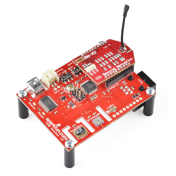
In one of the product images this is sitting on a USB Weather alone. Is it possible to combine just these 2 components to send HTTP GETs with the data from the Weather module to a web address?
man this things are flyin' you should stock in bigger quantities, because as soon as they are available they're gone!
By the looks of the comments above i dont think it works with
WRL-09976 xbee shield. Not without stuffing it anyway.
I was wondering if the following solution may work for electronic noobs like me.
Buy the following.
BOB-08276 Breakout Board for xbee module.
BOB-08745 Logic Level Convertor
Solder up the break out board and plug in the wifly into a breadboard.
Power it via the 3.3 volt arduino uno supply.
Use the logic level convertor to handle tx and rx from the arduino and the wifly board
Anybody think this would work ?
Thanks in advance.
According to my new knowledge that should work fine.
You can buy it from http://www.rovingnetworks.com/products/RN_XV
instead
I'm trying to get an RN-XV to work with an Arduino Uno and a XBee Shield (WRL-09976). Sending data to the Arduino works like a charm but sending from it does not work. I have tried both using pin 0 and 1 with the UART and pin 2 and 3 with SoftSerial. Same result.
If I plug the RN-XV into an XBee Explorer USB (WRL-08687) and connect it to my PC it works (sending and receiving) and I have stored a setup in the module that works with my network. I can connect to the RN-XV through my wifi network regardless of where it is plugged in as long as it has power.
As a last effort I have tried using a XBee Explorer Regulated (WRL-09132) wiring VCC, GND, DIN and DOUT in the same way as with the XBee Shield with the same result. Can receive but not send from the Arduino Uno.
As someone has suggested I have also tried to invert the DIN line to the RN-XV. No luck with that.
I’m stuck here. Can anyone enlighten me please? How can I get an RN-XV working with an Arduino Uno and a XBee Shield (WRL-09976)?
OK! Kind of fixed it my self. For some reason nothing is passed through diode attached to DIN on the XBee shield to the RN-XV. (Works fine with XBee modules....). So i removed it. Added a voltage divider between the Arduino TX-Pin and GND and connected the DIN pin to the divider. The sheld is now a 5V only shield but works with both Xbee and RN-XV. Voltage divider: TX-10K-DIN-20K-GND.
Same modification will probably work with the XBee Explorer Regulated (WRL-09132).
Now I'm happy!
Would you have a drawing of the mod?
(Is it possible to add the schematics and eagle files for this module or break-out board?)
*edit
It's a module from Rover Networks and the schematics are in the datasheet, my bad! The red board color threw me off :)
Can this little guy create its own ad-hoc network that I can connect my iphone to?
To be clear, I'm asking if it can be a host, or is it a client only module?
Yes - and Roving has an app in the Apple App store which is a terminal emulator that can help you. Look up Roving Networks in teh store, it is called WiFly client.
The manual answered my question: "In adhoc mode the module creates it own “on demand” network that you can connect to via your computer like you would to any other network." Sweet!
When is this item going to be back in stock ???
All right! back in stock 10/07/11.
60 units in stock as of 10/07/11, 0 units as of 10/10/11. Something tells me it's popular :)
I did'nt want to order more of this before after the weekend, luckily I checked the stock before going to work, and saw that they only had 17 units left. So I had to deside to order some then and there. And now I'm glad I did.
Anyway, I hope sparkfun will get more of these soon :)
I unfortunately live on the West Coast and by the time I got into the office they were already gone :( I know you get them when you get them but is there any idea when they will be in next? I guess I should just back order some instead of this happening I just had no idea that Sparkfun would get so few and that they would be gone this fast.
Ask and I received! Thanks SparkFun!
Has anyone got any idea of the lead time for this?
same day...
Can someone please share an example Sketch on how to get this to work in Serial mode with an Arduino Uno? I have downloaded the NewSoftSerial library, and can see that it has updated the Uno when running, but I have no idea how to continue to go from there. I am trying to control the MP3Trigger V2 through this connection. Also, is there a way to configure the WiFi settings from the Sketch rather than doing so in a AdHoc connection?
Thanks in advance!!
Tom
I'm using the "Breakout Board for XBee Module" to connect the "RN-XV WiFly Module" with Arduino and a breadboard.
Arduino 3.3 => Pin 1
Arduino GND => pin 10
Arduino RX 0 => pin 2
Arduino TX 1 => pin 3
The files "WiFly_Test.pde" and "Credentials.h" properly modified, give me an output with some errors, but the IP address from the router gets without a password and WPA2.
OK. Some minor progress. The jumpers on the ArduinoXbee are now on the Xbee and I have changed receive and send to 0 and 1 instead of the 2 and 3:
// Pins are 3 for INCOMING TO Arduino, 5 for OUTGOING TO Wifly
// Arduino WiFly
// 2 - receive TX (Send from Wifly, Receive to Arduino)
// 3 - send RX (Send from Arduino, Receive to WiFly)
WiFlySerial WiFly(0,1);
Now I am getting the following in the serial: Auto-Assoc roving1 chan=0 mode=NONE FAILED
TX light on the Arduino Uno blinks once in awhile but the RX light never turns on. Are my pins still set wrong?
Hi! finally you get the RN-VX to work with the ArduinoXBee v1.1 (M. Yarza) and Arduino UNO? both are compatible or do you need an 3.3v regulator for the RN-XV? Thanx in advance for your response :)
roving1 is the default access point RN uses to test the modules before shipping, all you have to do it change it with the set wlan ssid command. More info can be seen at: http://www.rovingnetworks.com/files/resources/RN_Product_Training2010v7.pdf
Now I am getting the following in the serial:
Auto-Assoc roving1, AUTO ASSOC IS LOOKING FOR ANY AVAILABLE WIFI TO CONNECT TO. BUT I FOUND IT WOULD NOT CONNECT AUTOMATICALY. I HAD TO MANUALLY SET THE WIFI DETAILS FOR IT TO CONNECT TO MY WIFI.
IF YOUR GETTING THIS RESPONSE IN THE SERIAL WINDOW, THEN THE XV TO ARDUINO CONNECTION IS WORKING.
you need to setup the rn-xv to connect with your home wifi. I used an Xbee regulated USB explorer for simplicity. I also used tera-term for the terminal client to connect to the xv via the USB regulated explorer. the user manual describes the commands needed to setup the xv with your home wifi.
I got as far as you, and I even could read messages send over UDP. But I had to preconfigure the wifly RN XV using XBee Explorer USB, since I wasn't able to enter the command mode using an Arduino and the Xbee shield.
Has any one accomplished that?
Hi All,
Been trying to get the RN-VX to work with the ArduinoXBee v1.1 (M. Yarza). I am using the WiFly_Test sketch (Tom Waldock) to test it out. The jumpers on the ArduinoXBee board are on the USB and the sketch is stopping at:
Starting WiFly Tester.
Free memory:971
Any tips on getting it to work would be much appreciated. Thanks!
Does any one know what the easiest way is to connect it to an Arduino Pro mini (5v) and have it generate an AdHoc network?
Anyone have any issues connecting to a router with this module? Ive been trying the speakerjet tutorial with no success. I can telnet to it by bringing pin 8 to high for Adhoc mode and ran the cmds to set the connections, but that did not work either. Help s much appreciated. Thanks!
EDIT: Never mind. Got it!
RS232 TX from WiFly Ver2.27 is INVERTED
ÖE"HiŒBdù³$’"KHLg“òÒ2RææSrRRæ–,,]féi9©¹)ÖE‘$iŒBdù³$’"KHLg“òÒ2RææSrRRf–,,]féi9©¹)Ö
Receiving this string on startup
??????
Are you looking at this with Hyperterminal? If so dont.... Hyperterminal is too automated and things are hard to debug - use teraterm instead.
http://www.rovingnetworks.com/files/resources/teraterm.zip
I'm trying to figure out page 5 of the datasheet. Are the resisters that it's talking about on the shield, or should they be installed externally. My reading of it is that they are on the shield (the default configuration), which would fix pins 13, 15, and 18 to GPIO. Does that sound correct?
I also don't understand the values for R8,11,17,20 (0R?).
Edit: Looking at the picture, which I can see better than the device itself ;-) It looks like the resisters are on the back of the shield. I would have to de-solder one of the 0 (0 ohms?) resisters on the back to add an additional sensor input. I'm assuming these resisters are intended to make the sensor inputs 3.3V compatible, whereas the reference manual states a 1.2V max.
Experiencing UART transmission gibberish at 9600-8N1 on start-up - using 4 wire hookup Vdd,Vss,RX,TX
thought?
I seem to recall hearing in the original Friday product update that you could use a U.FL connector and on inspection there is a footprint laid out for one.
The project I'm planning ends up requiring an external antenna.
So I guess my question is after soldering on a U.FL connector would it be prudent to remove the wire antenna or would leaving it there like a vestigial tail simply not cause any issues?
no - that is a test point for RN. It serves no function to the end customer. If you want a version of the XV with a uFL then you should order the RN-XV-U.
what is the communication range?
The datasheet says this can support up to 1Mbps using UART.
I need this speed to stream video from a quad-copter. Do you think this is possible?
Can this be used as Wi-Fi Webserver? Can Arduino handle this?
It can, but would be somewhat limited as it can handle max 4 concurrent connections. A web server you would probably want that number a little higher.
I am curious as to who decided on the PCB colour, is it SparkFun because their PCBs are usually red? Or was it RN's decision?
Sometimes there are mysteries that are never solved....
Roving Networks build and designed this, we had not control over the PCB color or anything else.
I had trouble with this device using an xbee regulated WRL-09132.
Sending commands throught it would not reach the RN-XV. Switched to the USB regulated Xbee, and Presto. I could send commands to it no problem. This might help others!!
Amazing...breakout board that only costs 6 more than the wifi module (RN-171, available elsewhere for 29)? Too bad it doesn't break out the SPI pins though...
Hi, does anyone know if the module can be used on a Arduino Fio? Has anyone tried this?
yes, works like a charm. Check out this post about my first project using this module with the FIO - http://vinterstitial.blogspot.com/2012/01/internet-doorbell-mk-i.html There is some example web server code at the bottom. The user manual is really useful in configuring it. I used xbee radios to program the FIO wirelessly, then just dropped in the configured wifly module and voila.
Can you show the flip side of your Arduino Fio paired with the RN-XV please, the pin outs are confusing me between these two, pin 1 to pin 1 doesn't make sense. Nice project btw!!
[update: finally noticed the outline shape marked on the Fio for xeebee shaped boards duh. would be nice though if the Fio had pin 1 marked correctly...]
Am I missing how far these can transmit and receive? I did a scan and did not see anything about how far they can talk to each other.
Range is a function of so many things * antenna design * antenna placement * antenna orientation * environment * PA and LNA capability
etc....
As the user - you are in charge of most of these variables.
Being that its 2.4Ghz (802.11) it will talk about as far as your laptop will from your router. Although placement of antenna, and even switching the antenna to a omni or patch antenna, will greatly increase range. I could be said they will 'talk' 20 feet and be valid, or they could be set up to 'talk' 20 miles, it all depends on much more then just the module itself. As always, when it comes to 'distance' - you mileage will vary.
can I make them connect to my home network and use them as a kind of Wireless Ethernet shield?? or do they just connect with each other?? it would be great!
Yep, these can be used as a wireless ethernet shield. They also support ad-hoc mode so you can have them connect and talk amongst themselves.
An I2C or SPI interface would be nice to allow for higher data rates.
I agree. However, this looks like it's designed to be a mostly drop-in replacement for the existing xbee shields which also just use the uart interface.
Can this board act a a replacement for the wifly shield?
Depending on how its configured, it can be a replacement to the wifly shield AND a arduino. As long as you stay within the specs and limit the analog sensors, you can use this as a stand-alone device without a arduino all together, after its correctly configured, just like a xbee.
Based on specs and what I can see visualy, it does not have the SPI-to-UART (SC16IS750) chip. That means the Arduino's UART (pin 0 and 1) has to do the talking, instead of using the SPI header (pins 10,11,12, 13).
Does any one know the spec difference between this RN-XV and the WiFly GSX breakout (below) that might account for the price differential? Is it the built-in antenna or ufl connector on the GSX? Is the RN-XV less functional somehow?
The GSX breakout uses the RN-131C which is much more expensive than the RN-171 used by this RN-XV.
The only reason for this that I could find in the specs is the power. The 131 is 18dB whereas the 171 is up to 12dB... that's about 4-5 times more powerful !
Dan
Looks like the big difference is this doesn't support 802.11 N (the Digi XBee does), but I highly doubt needing N speeds for transmitting serial data!
This is awesome because it's cheaper than the new XBee WiFi module!
and much easier to use!