- Home
- Product Categories
- EL
- SparkFun EL Escudo Dos

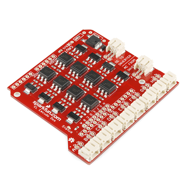
SparkFun EL Escudo Dos
We've heard you, and made a number of improvements to our EL Shield. The new version adds zero-crossing optoisolated triacs for noise-free operation and full isolation between the AC and DC sides, and includes a 1.5A adjustable linear regulator to supply regulated DC to an external inverter (not included).
The SparkFun EL Escudo Dos is an Arduino shield for controlling up to eight strands of electroluminescent wire. EL wire is flexible plastic cord that glows brightly when high-voltage AC is applied to it. It's available in numerous colors (see the related products below), runs cool, and requires very little current, but can be difficult to work with because of the high-voltage requirements. The El Escudo Dos contains circuitry to safely switch high-voltage AC on and off, allowing you to create animated displays or whatever else your imagination can come up with.
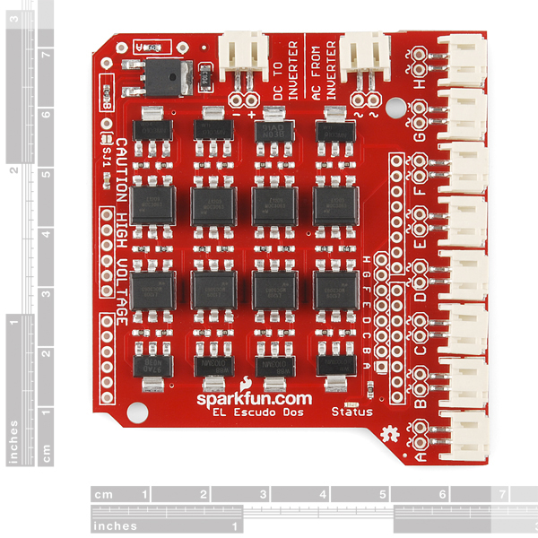
In addition to this shield, you will need Arduino headers (see the related products below), an inverter (a component that generates the high-voltage AC needed by EL wire), and the EL wire itself. SparkFun carries two inverters, a 3V-input version that can drive a few feet of EL wire, and a 12V-input version capable of driving dozens of feet of EL wire. Choose the one appropriate to your power source and driving requirements. The shield's built-in regulator comes preset to 3.3V, but can be set to any voltage by changing two resistors, or bypassed with a solder jumper to send the Arduino's RAW voltage directly to the inverter (perfect for 12V setups!). See the tutorial below.
Nate has used EL wire to make amazing interactive costumes; check out his Heartbeat Straitjacket and demo video.
- Eight opto-isolated, zero-crossing control channels
- No library needed - control is as easy as turning a LED on and off
- Shield is compatible with 5V or 3.3V Arduinos
- Integrated 1.5A linear regulator (LM317) to supply regulated DC power to external inverter
- Linear regulator preset to 3.3V, but can be changed via PTH resistors, or bypassed entirely
- External inverter required, not included
- Comes without headers, soldering required
- Schematic
- Eagle files
- Hookup Guide
- Example code
- Datasheet (MOC3063S)
- Datasheet (Z0103MN)
- Datasheet (LM317)
- Tutorial: setting up an EL system
- Jacob's Ladder Project
- GitHub
SparkFun EL Escudo Dos Product Help and Resources
Sound Reactive EL Wire Costume
December 31, 2015
Learn how to make your EL wire costumes sound reactive in this project tutorial.
Modifying Your EL Wire Inverter
July 18, 2019
In this tutorial, we will modify the 12V EL wire inverter to power the EL Sequencer/EL Escudo Dos off a single power supply.
EL Sequencer/Escudo Dos Hookup Guide
December 3, 2015
A basic guide to getting started with the SparkFun EL Sequencer and Escudo Dos to control electroluminescence (EL) wire, panels, and strips.
Core Skill: Soldering
This skill defines how difficult the soldering is on a particular product. It might be a couple simple solder joints, or require special reflow tools.
Skill Level: Noob - Some basic soldering is required, but it is limited to a just a few pins, basic through-hole soldering, and couple (if any) polarized components. A basic soldering iron is all you should need.
See all skill levels
Core Skill: Programming
If a board needs code or communicates somehow, you're going to need to know how to program or interface with it. The programming skill is all about communication and code.
Skill Level: Rookie - You will need a better fundamental understand of what code is, and how it works. You will be using beginner-level software and development tools like Arduino. You will be dealing directly with code, but numerous examples and libraries are available. Sensors or shields will communicate with serial or TTL.
See all skill levels
Core Skill: Electrical Prototyping
If it requires power, you need to know how much, what all the pins do, and how to hook it up. You may need to reference datasheets, schematics, and know the ins and outs of electronics.
Skill Level: Competent - You will be required to reference a datasheet or schematic to know how to use a component. Your knowledge of a datasheet will only require basic features like power requirements, pinouts, or communications type. Also, you may need a power supply that?s greater than 12V or more than 1A worth of current.
See all skill levels
Comments
Looking for answers to technical questions?
We welcome your comments and suggestions below. However, if you are looking for solutions to technical questions please see our Technical Assistance page.
Customer Reviews
4.2 out of 5
Based on 10 ratings:
1 of 1 found this helpful:
Makes Sequencing A Breeze
I purchased two of these for student EL Wire projects in my classroom. One group had a basic EL Wire sequence powered from a 12V input up and running in under two class periods. The coding involved is simple and easy to modify for different effects and patterns. The second group messed up on their initial soldering and had to do some significant work to fix their mistake. Not sure if they messed something up in the re-soldering process but this board's "DC to Inverter" port will now only throughput a max 3V which is barely enough to light up the EL wire. We ended up having to bypass this port altogether and power the inverter and the Arduino board separately to get it to work. Overall, a fun little shield that allows for fairly complex EL wire projects with minimal difficulty.
1 of 1 found this helpful:
Have some issues
Intermittent issues where an EL wire stays on even when logic says it should be off. Have LED wired to same pin which shows proper logic. Ordered 2nd board which had the same issues on different pins. Found that I could hide the problem by turning all EL segments off, then turning them back on.
Hi, This sounds like it could be a couple of things causing your issues. Please contact us at techsupport at sparkfun.com for more assistance.
worked well with arduino uno.
Cool device, easy to settup. Small and powerful. Ran 12v threw the inverter to power about 40 ft.
Great except for hookup problems
This thing is a beast. I did have some issues getting it connected to my project. The EL tape I had didn't have the right connector. I noticed that Sparkfun does sell loose JST connectors, but I'm too damn cheap to buy eight connectors at $.95 per. So I soldered the EL leads directly to the board. Given my skill set, there was one short in my soldering that sent up wisps of smoke when it was energized. I fixed it and now it works fine. Surviving the rough handing and short is a testament to how well this board works.
Great shield!
Started playing around with EL wire recently and this is a great little shield! Though the connectors didn't match the connectors on my EL wire (I purchased the EL wire from another source), I was able to make 8 new connectors with some I already had. I'm also using the 12v inverter since I'm using 9 foot EL wires on each channel. That's about 72 feet of EL wire! Super easy to use and program!
Gets 8 EL wires connected to Raspberry Pi
The board works well. I connected the Pi GPIO pins to the 8 connections labeled A through H and a connection to ground (I am not using the 5 volt option). This makes for a messy bundle of wires. It would have been great to have a header that I could run flat cable over to the Pi proto board where I would then connect the gpio pins and the ground (and I guess the 5v for those that will be using it). I know the board is really designed for Arduino but one header would make it easy to use with a Pi.
No complaints
I am using the board to light the inside of a cabinet when the door is opened. Every time* the lights come on as advertised. (*except when I messed up the Arduino code for several hours...)
good
works just as i wanted them too perfect for my project and good price
I don't know what to do anymore.
All I wanted to do is turn on the EL Wires 1 by 1 and once they are all turned on, I want to turn them off 1 by 1 for the initial testing phase. But, no. It would just stay on. My test code is super simple, so don't think that's problem.
It's really hard to use on my current project (It's like a VU Meter, but on a shutter shades) where I will use a sound sensor and/or an audio analyzer module to turn on 2 EL Wires once a certain value has been reached.
It's a bit frustrating because when all of the EL Wires has been turned on, something would emit a high-pitched noise and the EL Wires would stay on and would not turn off anymore, until I unplug the Arduino and plug it in again.
I have tried to use a KY-038 and KY-037 sound sensors, a 7 Band Spectrum Audio Analyzer Module and Sound Sensor from a different vendor and still getting the same result.
I even bought a genuine Arduino UNO just to try my luck, but still got the same result, unfortunately. I guess I'd just include this project on my re-visit folder.
The customer service is spectacular, tho. So, that's good.
Worked real fine
It worked surprisingly well for Arduino shields! half of the ELwires behaved differently but I suspect that's not caused by the Escudo Dos. A recommandation for sensor input - ELwire output installations!
I am making a costume that uses several short strips of parallel electrode EL tape. I am running 4in long 0.5in wide parallel tape out of each channel. The tape is very dim compared to when I run the tape off a standard inverter even when only one channel is on. I am using the 12V inverter jumped to the board as recommended by the hook up guide. Any suggestions as to why it is so dim? Should I be using at different inverter (I read somewhere that EL wire and parallel electrode EL tape run on the same voltage and frequency)?
Here are a few things to try. 1: if you connect the output of the 12V inverter directly to your tape, is it brighter or still dim? (This will tell us if the board or the inverter is at fault). 2: If it's dim and you have a better inverter, you can always connect the better inverter to the board. 3: the Dos is great at running long lengths of EL but doesn't always do well with short lengths (it needs a minimum load to turn on and off efficiently). You can try shorting a 100k resistor across the output (the pairs of holes marked "~ ~" on the bottom of the board are perfect for this) and see if that helps. 4: Our tech support department is great at solving problems like this; give them a try.
One more thought - if you're using Sparkfun's 12V inverter, ensure that you're running your Arduino with a 12V supply, and that solder jumper SJ1 is closed with a blob of solder to bypass the regulator. Otherwise the 12V inverter output will only be getting 3.3V from the regulator, which will definitely result in dim wire.
Connectors are incompatible with all the el wire I've ever used/purchased, so needs a load of adapters making.
The regulator will not deliver anywhere near 1.5A - this regulator is rated at 500mA.!!
Slightly better than the old board (which really was a pile of cr*p) but not much.
What are the required pins I need to connect if I want to attach the arduino micro to the el escudo dos via wires? I'm using the micro because I needed to save space. I already have a 3v inverter attached and el wire in one of the connectors.
Does this card include resistors on the output side of the triacs to draw the holding current required by the triacs? I not, what is the holding current spec for these triacs?
There are links the schematic and triac datasheet in the product description above, those documents should answer your questions.
I have not been able to find a inverter large enough to drive the long lengths on all 8 channels at the same time of generation 3 EL wire, so I need to use 2 inverters to drive that much wire can I split the HV feed on the board in 1/2 on the board by cutting the trace and attach the second inverter to feed the other 4 Tri or is their another way also will their be any problems with doing it this way or any repercussions to the EL Escudo Dos or the Arduino Uno 3
Hi, I have the same problem. Since the board is used in a costume, sometimes an EL wire causes a short circuit because of moving with the suit. So if one of the 8 channels has a short, the whole costume doesn't work anymore. The boards worked the last 6 months in this configuration. Now to solve this I separated the HV and HVGND of each pair of channels by cutting the traces, and connected 4 inverters. So when one pair of channels has a short, the other 3 pairs remain working. I would think this should work, because there are now 4 separate isolated circuits. But somehow after this modification now some of the triacs are blown after a few seconds/minutes of use! Some are 'always on', some light up erratically. I don't have a clue what could cause this, I have 6 boards and 3 of them have this fenomena. (I'm afraid of further frying the other 3). Now I'm thinking of reconnecting all the HVGND connections, so all the inverters share the same HVGND, maybe this will solve the issue? I'll try this weekend... Or does someone have a clue?
Well I've tried it, interconnected all the HVGND with the AC ground sides of all the inverters (the AC Wire which has the least resistance with the 12VDC input GND). But after a couple of minutes the Z0103MN's are blowing one after the other...
Now I'm out of ideas.. such a simple circuit and I don't have any clue of why the triacs are blowing up... Could it be the inverters? Can they be too strong for the triacs? They're normal small inverters for 10m, powered on 12VDC.
Hello, i programmed a squenz for my Arduino Uno & the EL Escudo Dos and i have to start it now synchronized with music on my PC. Whats the easiest way to send a signal from a remote controller to the Arduino to start the Sequenz and at the same time a signal to the PC to start the music?
Regards
Hey, i got this one with an Arduino Uno and it works all fine so far. Now i need the fade function but the "EL.fade_in" doesn't work without library. Can you tell me pls the command for this Escudo Dos cause here it says "•No library needed"
Regards
There isn't a provided fade command or library, but you can use PWM (analogWrite) on channels B,D,E and H, or write your own fast-blink code for any channel.
Note that fading burned out the triacs on the old EL Escudo, so the newer Dos version has zero-crossing triacs that are bulletproof, but don't fade as smoothly as the old one. If you use analogWrite, you'll notice that some dimming levels flicker. You should still be able to find PWM values that give you broad but stable dimming steps.
Can I get a NeoPixel ring RGB LED working with this Shield?
As long as you change the NeoPixel data pin to something unused by this shield (the shield uses pins D2 through D10), you shouldn't have any problems.
Hi! I am looking to put together a failry large EL wire project. I am curious whether, with the right combination of inverter and this unit (or the EL sequencer https://www.sparkfun.com/products/11323) I can run 8x 5m lengths of 5mm (or 2.3mm) EL wire. Also, I am wondering whether there are any digital or analog inputs for the arduino left on this shield, so that I can attach my own sensors to the system (likewise on the el sequencer above). I'd appreciate any advice you can offer!
The AC switches on this shield should be able to handle that load, provided you have a strong enough inverter. This shield only uses D2 through D10, leaving the rest of the digital and all of the analog pins free.
Hi, I'm also making light-up suits, and we are wanting to have a button to start the sequence when we hit the button, what pins, if any can we use to have a button be a control? Thanks in advance!
D11, D12, and D13 are all digital pins available for a button connection, if you aren't stacking anything else on your Arduino requiring those pins.
Hi, I have an EL Escudo dos, but found that I will need more channels. Is it possible to use charlieplexing or another technique to do this with just one El Escudo dos? Thanks!
Hi, Im looking into creating a suit with el wire an arduino and a EL Escudo dos. Now I saw there is a "new" kind of wire called a Chasing wire. i.e. http://www.elwirecraft.co.uk/340/el-wire-categories/chasing-el-wire-5-pm-3-2mm-with-smooth-chasing-motion-effect/ Now I was wondering if there is a way how i can have one of the Escudo channels drive one of these chasing wires.
I am quite inexperienced in all this so if you could give any advice if this is at all possible I'd really appreciate it!
I would not mind having the arduino drive the chasing wire separately along side the Escudo as long as I can drive it with the arduino in some way.
Thanks!!
Thank you for pointing out that new wire! It looks really neat and we're looking into what it would take to drive it. Our best guess at this point is that it combines several EL channels into one wire, so you'd need to allocate several (3?) channels of your EL Escudo / EL Sequencer for each strand of chasing wire. Software wise this would be easy enough to drive, you'd just repeatedly sequence through the channels. Hardware wise they say it uses a special connector, so you'd need to either find the matching connector (we're looking into it), or cut off their connector and splice on several JST pigtails to match our driver boards. If you do get some, let us know how it works and if we can help further.
Hi there, I just tried to attached to drive my chasing/flowing EL wire with the Escudo Dos and it seems like it should work, but for some reason I cannot seem to make it work. The wire appears to be three main conductors, with each sharing a common connection to the thin wrap around wires - so I was thinking I need to connect the legs of three channels all together and connect that to the wire that goes to the common conductors and then just attach the individual main conductors as usual. However the inverter does not even activate when I do this, but work fine as soon as I remove the common conductor link - so it seems like I am just grounding the entire circuit or something? Any helpful tips?
We've been successfully experimenting with these wires and hopefully we'll have some products on the storefront soon. The wire has a common lead (down the center of the strand) and three corona leads which spiral around it. When you turn them on one at a time in sequence, you get the cool flowing effect.
We've been working on an adapter to connect this wire to our EL products. If you have three JST pigtails, you can do the same thing by cutting off the connector on the chasing EL wire, connecting one pigtail's black wire to the black wire (common) on the EL, then connecting the remaining three red wires to the white/yellow/red wires on the EL. (The order will affect whether you sequence backward or forward, which you can always change in your software.)
Note that even though AC doesn't have polarity, the connectors on our EL drivers have an "output" and a "return" side that you need to get right if you're combining signals like this. (That may have been your problem.) We hope this helps! Let us know if you have further questions or problems, and have fun!
Oh! Ok that makes perfect sense, thanks for the info. Can't wait to see the products.
Awesome. Thank you for your reply. I just ordered the Escudo dos from a uk website and I'm going to get the wires as soon as I finish my design. When I get the wires I'll let you know whats inside the special inverter. Thank you for your help so far!!
I received the chasing el wire and got the specialized inverter. I made some images of the inverter itself. http://i43.tinypic.com/fp9mp5.jpg http://i44.tinypic.com/30m61pw.jpg
It looks like it uses two channels that are alternated creating the "chasing effect" being driven by 2 AA batteries. Once I receive the normal 12v inverter I will try to connect them to the Escudo Dos to see if it can drive it. I will keep you posted of the results.
Edit: It seems like its indeed two channels just alternately "flashing". I can hook up a normal el wire to each channel separately and it will just flash. So fingers crossed it will "just" work when two channels to the escudo.
Edit: (for anyone else looking for this info) Nope I was wrong there are 3 channels and one ground wire. It does work like a charm though!! The standard inverter that gets shipped with the wire is a basic flashing sequencer that flashes each channel after the other. This gives the chasing effect. I added some more info on how to solder and handle the wires here.http://www.instructables.com/id/Soldering-Chasing-EL-Wire/ I will add another tutorial on how to hook them up to the Arduino and Escudo later!
I plugged the EL Escudo Dos into two Arduinos and it seems to have fried them both. I'm not sure of that but I wanted to check in before plugging in another device. Let me tell you more about my configuration:
I soldered the SJ1 jumper so the inverter would run at 12 volts. The Leonardo can't be programmed any more; I plug it in and it blinks but when I start to Upload and it just gets tired about 1/2 way through. The Uno has a power light but just sits there.
Any thoughts?
We're very sorry to hear about your problems. The EL Escudo has two identical connectors for DC out and AC in; is it possible that your inverter output was plugged into the DC out connector? This would send 100VAC+ into the VIN line likely damaging any Arduino plugged into the board. Again, sorry for your problems, please contact our Tech Support department, who will be able to assist you further.
I just checked and it isn't hooked up backwards. One set of wires is red and black, I cut off the 9V battery snap and attached it to "DC to Inverter"; the red is positive (but I've heard one shouldn't count on that). I hooked the two black wires to "AC in from Inverter".
I'll give Tech Support a call, thanks.
Would I be able to use the ELastoLite panels with this?
I made a small project with 8 small sections of EL wire connected to El Escudo, and then placed on a locally made arduino (Gizduino, made here in Manila). When i sequence the lights with a loop, it always glitches and gets frozen on a particular wire. It seems to be hardware related, because when i change the code, it glitches on the same wire. Recently, i took the shield off the arduino to inspect for problems. When i replaced it, the glitch had moved to a new wire. Any thoughts as to why?
Can you tell if the Arduino itself is frozen, or just the shield? (For example, keep blinking the status LED; if the status LED stops you know the Arduino has frozen up).
My first guess is that your inverter + EL wire is drawing too much power from the Arduino, and that the Arduino is locking up. Ensure that you're powering the Arduino with a sufficient power supply for both the Arduino and your EL wire (9 or 12V wall wart recommended), or power the Inverter separately from the Arduino. If you continue to have problems, let our Technical Support department know and they'll be happy to help you out.
i ran the same code with the status light blinking. When it freezes, one wire stays frozen on (usually the same wire), and the status light also freezes. so i guess the manila-produced arduino is freezing up.
I am powering the arduino / sheild with a 9 V wall wart. i then use an El Inverter 3V between the arduino and sheild. Should i use the El Inverter 12 V? i have that product also, but have not connected it yet because my project is so small. all 8 of my EL wires are only about 20 cm. I also have an imported name brand Arduino. Should i use that and see if the freezing up still occurs?
i swapped the Manila-made arduino for the Italian-made Arduino-Uno. That fixed the freezing issue. However, on future EL-wiring projects for my students, i'd like to still use the locally made arduinos. Any thoughts on how i can keep them from freezing? In order to power the inverter seperately from the Arduino, what is the easiest way? i don't have to use 2 wall warts do I?
It's hard to tell why the Gizduino is locking up and the Uno isn't, since the inverter is powered by the "VIN" pin which comes straight from your power supply. As far as the VIN pin goes, there shouldn't be any difference between the two boards. In other words, it's very strange that if you're using the exact same power supply, the Gizduino won't work and the Uno does.
Have you tried this on both wall wart and USB power? What voltage is your wall wart? (It should be 6.5V to 12V). Are you using a 3V or a 12V inverter? If you continue to have problems, I recommend contacting our Tech Support department for deeper troubleshooting.
Hi Mike, Now doing this project with students and having a new problem. Particular channels from the shield will stay on, even though our code says to turn them off. Upon jiggling the offending wire, it will shut off, but then then when the code turns it on again, it must be jiggled again, otherwise it remains on forever. If i move offending wire to a new channel, the problem follows the wire.
This seems to appear for students who are using the 12V inverter (with SJ1 closed). Those students with the 3 V inverter do not seem to be having this problem. any thoughts on why this is?
I can't find see any problem with the offending wire, nor understand why the problem appears only with the 12V inverter?
i think i solved the problem. I got an adjustable voltage wall wart and turned it down to somewhere between 7 and 8 volts. (my previous power source was 9 V). Now it's been running for over an hour with no glitches. Thanks for the trouble shooting!
I have tried this on USB power, and have not noticed it locking up. however, i have only tried the USB power for maybe a few minutes at a time. (the locking up usually occurs after a leave for awhile). the wall wart is 9V and i use a 3V inverter.
Forgive my ignorance, but if these ELwires/panels use 110 volts AC, will they light up just by connecting them to household 110VAC?
Yes you can, although it will run a bit dimmer than with an inverter. (The brightness is partially a function of the AC frequency; the higher the frequency, the brighter the output.)
From looking at the code sample and schematic it seems a Microchip MCU can work with this, has anyone done it yet?
You're right; anything with eight output pins (3.3V or 5V) can easily interface to this board.
Will this shield work with bigger 12v inverters that can power 30-50m of el wire? I'm doing a project that requires controlling around 150m of wire and was hoping to control it using an arduino and this shield
We haven’t tested it all the way to these limits, but a rule of thumb I’ve seen is that each meter of EL wire uses 10mA or so of current. The triacs in the EL Escudo Dos are rated at 1A continuous and 8A peak. So in theory, each channel should be able to drive 100m (328') of wire without issues, and more if it’s not on continuously. Let us know how it works!
Great shield. I soldered a max485 chip and 3 pin header directly to the back of it so now I have a DMX controlled version!
Is there a way for the EL Wire to go from dim to bright using the El Escudo Dos?
We've covered this in these comments before. The quick answer is you can get several broad steps from dim to bright, but not smooth dimming.
how can i set usb on el escudo dos ?
Hi, Why is there DC to inverter on Escudo?
It's best to have a separate regulator for the inverter since it may need a specific voltage at more current than the Arduino can provide on its own.
Hi, whats for the two resistors 330 on every triac? I finded some el wire controllers that don't use that..
We did the math and added them to make this board as robust as possible. Your mileage may vary with other designs.
Hi, why there are two Triacs per channel? Why not only the MOC?
We might have been able to get away with just the optotriacs, but they're traditionally not as beefy as discrete triacs, and we wanted to ensure that people with higher-current needs were accommodated.
So, if i use only the MOC, how much length of el wire i can use?
And if i use this MAC97A8 http://www.nxp.com/documents/data_sheet/MAC97A8_A6.pdf) insted f Z0103 it will work right? Because they are almost identical, the only main difference is that the MAC97A8have a IT(RMS) 0.6A versus 1A on the Z0103.
Thanks
The quick answer is I don't know, you'll need to do the analysis yourself to find out. Let us know how it works!
Thanks a lot for the quick response :)
Is this compatible with the Arduino Mega or Uno R3?
Yes. We have seen some problems with the Uno not putting out a full 5V on the VIN pin when powered via USB, which causes the 3.3V regulator on the EL Escudo to malfunction. If you're not using USB for power (or you're bypassing the regulator), then it should work fine.
hi everyone is there any possibility to build up a system that provides 16 ports with one arduino board? and without a forfeit? ;) greetings from switzerland
It is possible, with some hacking, to get two of these boards running on one Arduino. You'd need to cut the traces on one, and run those channels to open pins (16 will almost max it out).
You could also do this with two EL Sequencers, by connecting them together via serial and programming one to be the master controller and the second to be a slave.
i very like your second idea, but how would i have to connect them to the arduino that i can make a programm that will do 16 different actions? :S thanks
Yep, as Toni said, the Sequencers are themselves Arduinos. There are a lot of ways to do this, but one way is to program one of them (the master) to run your sequence on channels 1-16. If the current channel is 1-8, do it on the local board. If it is 9-16, send a message to the other board (which you'd program to listen for such messages and turn on/off the requested channel).
thank you for all the ideas, i will see what i can do..
The EL Sequencers have their own ATMega IC on them, allowing you to program the Sequencer itself, thus not requiring an Arduino. For more project ideas using the EL Sequencer and the Escudo, check out our forum.
I've been looking online for more powerful inverters (1A) and all of what I've found gives an aoutput of 110V and 50 or 60 Hz, is this frequency enough to run EL Wire?
ok i just got two escudo dos's, arduinos and 12 v inverters and el wire, example code is loaded, grean status light blinks everything is hooked up i get no light at all out of the el wire, im trying to run it off of the usb power i have soldered the Sj1 jumper, when i measure the DC voltage from the DC To Inverter side i get nothing at all, when i measure the voltage regulator i see 1.6 there absolutely nothing coming from the inverter both ac and dc side, please help.
USB is only 5V, which isn't enough to run the 12V inverters. If you're using 12V inverters, you will need 12V supplies for the Arduinos, and (as you already have,) you will need to close SJ1 to send 12V directly to the inverters. Then your systems should work fine.
See the tutorial at the top of this page, which walks you through all the power options.
I ordered this product a few days ago and I just realized this isn't compatible with my Arduino Due because of the spacing between the headers. My plan is to make it a shield anyways and wire it seperate from my Due, which pins do I need to use at a minimum to get this working (I have an external 12v inverter)?
Edit: I have realized I am an idiot. I looked at a pinout on my Due and realized the reason why it wasn't fitting is because I wasn't connecting the shield to the right place >.
It looks like all the El Escudo Dos digital pins are loaded with a series diode & 390 ohm resistor. I have an Arduino Uno. If I use the El Escudo Dos, am I losing the ability to use the external interrupts available on D2 and D3 (I'm trying to add an interrupt driven rotary encoder on the same project)?
If so, is there a way on the El Escudo Dos, if I don't need EL_A and EL_B, that I can recover the use of D2 and D3 without cutting traces, for instance. I'm thinking of cutting the shield pins for D2 and D3 as the most practical, reversible solution.
A Leonardo is attractive, but I'd like to keep serial available for debugging.
We designed the board so that you could cut the traces between the Arduino and the various channels (e.g. A/D2 and B/D3) and patch those channels to unused I/O pins if you like. But (and I haven't tried this), I suspect that you can set up D2 and D3 to be inputs and use the interrupts without modification as long as you don't mind that a HIGH input (or pullup) would turn on that channel (you don't need to connect anything to it).
I need this to fit in a tighter spot. I'm thinking of cutting it like this. I haven't figured out how to use the A-H holes yet.
You probably don't want to do that; you'll lose all the outputs, which are the eight headers with the "~" symbols. The smaller row of 8 headers are the logic/LED inputs.
You might take a look at the EL Sequencer, which is about as narrow as what you want, but a bit longer in one dimension. You could also make your own PCB.
Thanks for the heads-up. I can chop it, just not as far as i hoped.
I've seen inverters online that claim to make the EL wire brighter by pushing the frequency up to 8khz. ( at expense of life ) is this true? can the Escudo handle that kind of inverter?
The back of the envelope says that the triacs should be able to handle up to 50kHz, so I'd guess such an inverter would work OK. If you try it, let us know how it goes!
Has anyone tested this board with a 3.3V Arduino? The Features List says it's compatible with 3.3V Arduinos, but that doesn't seem to be the case. I can't get any of the channels to trigger on a 3.3V input. 5V works every time.
Strange; we've successfully used it with a 3.3V Arduino Pro. Is that what you're using?
EDIT: Also ensure that the inverter regulator is correctly configured for your power supply; your inverter may not be getting the voltage it needs from the 3.3V Arduino.
I was using a IOIO. When they didn't light, I took a 3.3V from the regulator and supplied it to each channel...nothing. The inverter is 12V being supplied from a wall supply. The strands light when I give the pin 5V.
Check to see if your IOIO output(s) can light up the status LED on pin 10. The eight inputs go to optoisolators, which are effectively 5mA LEDs with a 390 Ohm resistor. If your output can light a LED, it should be able to turn on an output channel. Keep us posted.
So, I checked the LED, and it worked. Got suspicious. All the channels light on 3.3V except A and B...which, of course, having only two strips for testing, are the ones I had plugged in. I'll do more investigation and see if it's a faulty board or what. Should I consider a return?
Check the solder connections on the driver parts for A and B, but if you don't find anything obvious please do contact our customer service department. We test 100% of these but occasionally things slip through the cracks. I don't think there's anything you could have done to kill the inputs if you weren't putting e.g. 12V onto them. Sorry for the inconvenience, we'll get you up and running as soon as we can!
Where can i find a diagram how to connect 'EL Escudo Dos ' to my arduino?
See the tutorial linked in the documents at the top of the page. The one sentence version is: solder headers to the EL Escudo Dos, and plug it in.
hello i need something like that but for Raspeberry pi. do you plan to build one or is it easily customizable to connect it to the Raspberry pi gpio ?
We're not immediately planning on making a version for the Pi, but the requirements of this board are very simple, and it should be easy enough to wire eight digital outputs from the Pi into this board. I believe I've seen a Pi-to-Arduino-shield adapter board out there that may help as well (this board uses pins D2 through D9). Let us know how it goes!
Silly question.... Eight channels? Why eight?
If it had ten, there are some rather interesting ideas I (we) could explore. In a perfect world, ten channels and stackable would be great. I've got a rather interesting idea for 32 legnths of EL wire.
That sounds like a great project! When you're designing something like this, you have to balance a lot of things, the number of output channels being a large one. More channels make a board larger and more expensive, with fewer people buying it because they don't need that capability. Eight channels seemed like a good balance between too few and too many, but thanks for the feedback; we're working on a stackable version for those of you who need to drive LOTS of channels. Also take a look at the EL Sequencer, which could be synchronized with other boards via software.
Looking at the Z0103MN datasheet, this should be able to handle strings of led christmas lights at 115v 60hz. Anybody else tried that? I'll experiment with an isolation transformer and report back.
Hello,
Are connectors JST or micro JST can anyone tell me dimension of these connectors used on this board ?
Thanks
This was answered earlier in these comments (link), if that doesn't answer your question let us know.
Hello, I was wondering if this shield could be program by connecting it to the computer by connecting a FTDI cable to header pins. This could be done with the old El Sequencer. Is it the same for this Escudo Dos, or I really have to buy an Arduino Board?
Thanks.
The bottom line is that this shield needs eight digital outputs to control the eight EL channels. You can supply those lines from whatever you like (microcontroller, shift-register, etc.), but an FTDI cable doesn't have eight directly-controllable outputs, so that won't really help you here. If you want to control the eight channels from a computer via FTDI, you will need either an Arduino plus this shield, or an EL Sequencer (which has the Arduino built in to it).
I have 8 loops of EL wire on this, which is 8 positive wires and 8 ground wires. I see on the EL Escudo Dos schematic that all of the EL grounds are tied to the inverter ground. Could I tie all of the EL wire grounds together and run one wire down to the inverter ground? It'd cut the number of wires down from 16 to 9, which would help with my tight space requirements. Thanks in advance for any help!
Sorry for the late reply; for normal AC loads you'd need to be careful the combined current coming back on the common wire, but for EL this should work fine. Just ensure you're common-ing the correct side of the JST connectors, and try to keep the bundle tight to reduce possible radiated interference. Good luck!
I'm thinking of making a VU meter using EL wire by connecting this shield up to a VU chip such as a LM3916/LM3915/LM3914, or a pair of LM324 amps with each Vout going to an EL terminal (see http://www.zen22142.zen.co.uk/Circuits/Audio/vumeter.htm). Apart from the dimming issue, would there be any problems with this setup?
No issues I can see, if your external circuit can light up an LED (5mA), you should be able to hack straight into the shield. Send us some video when you're done!
I'm pretty familiar with DC but not so much with AC. Is there a way to multiplex from this board so I can light say, 100 different strands in sequence? I see in the comments above that you can't just stack these boards because they use specific Arduino pins.
Can this board able to dim el wire, Please help
https://www.sparkfun.com/products/10878#comment-4fea44edce395f416a000000
Is there a standard name and or size for the connectors that fit with the board? I have been searching all over town for something that fits to no avail. I found some JST connectors at a hobby shop but they aren't the right shape/size. I have a slightly larger version of the connector that I got from coolneon.com but can't find anything on their site about the connection either.
It's a 2mm, 2-pin JST connector. We offer pigtails with this connector that you can easily splice onto your EL wire/tape/panels. You could also get the parts to build these connectors at Digi-Key, but you would have to crimp the pins yourself which is not easy.
Thanks for the help. I'll have to call around some more. I should have ordered some when I placed my original order but I figured the existing connectors I had were the right size. My biggest problem now is the time/cost it would take to ship.
I can't seem to get my EL Wire to turn on. I've got the El Escudo sitting on my Arudino. I'm running a program that should keep the H connector and Status light on (which it does), but the wire just doesn't light up.
I used my multimeter to see if a current is running through the wire; it is. I'm still a complete newbie at this, so I don't even know if I'm reading the multimeter correctly, but I do know that the same number shows up when I touch the leads to the two pins at the H connector and at the end of the EL Wire.
I'm using the 3V inverter on about 3.5 feet of wire. My understanding is that that should be sufficient.
I've tried running the Arduino off the USB power and a 9V battery. Neither work. I looked around the Internet, and something tells me I might be missing an additional battery/el driver (I don't know what that is), but there was no indication of it here.
Any and all help is appreciated. Thank you.
Also, the tutorial linked at the top of this page has a good walk-through of all the steps necessary to get the EL Escudo working.
OK, let's check a few things.
Is the 3V inverter plugged into the EL Escudo with the red/black lead to the "DC TO INVERTER" connector, and the black/black lead to the "AC FROM INVERTER" connector?
Set your multimeter for AC Volts (and if it's not autorange, set the range to 200V or above). Now with everything powered on, carefully measure the voltage at the two holes just above the "AC FROM INVERTER" connector on the EL Escudo. (Run the red lead to one hole, and the black lead to the other hole. It doesn't matter which direction). You should see over 100V.
Let us know what you see, and we'll keep troubleshooting.
Yes, the black and red JST is plugged into the DC and the black-black JST is plugged into the AC.
Here are the results of the multimeter test (placing the leads on the AC FROM INVERTER holes):
200V - 0.0 20 - 0.01 2 - 0.1 200m - 13.3
I'm guessing this is the problem? Could it be something wrong with the inverter? What else would cause what I'm assuming is very little voltage to be getting through?
Yes, there's no AC coming from the inverter, so no glow. :(
Now set your multimeter for DC (20V range), and check the two holes by the "DC TO INVERTER" connector. You should see close to 3.3V. If there's 3.3V here, but no AC, then the inverter is bad. If you don't see 3.3V here, let me know and we'll keep troubleshooting.
Okay, I set the multimeter to 200 in the top-right section (V~
Do you have the Sparkfun multimeter? If so, "V~" indicates AC volts, and "V=" (with dots under the line) indicates DC volts.
Ahem. I didn't realize that the tilde-close parens would be a problem for the comment system.
I set it to 200 V= (solid over dots) and put the leads in the DC holes. It reads 1.2, which is less than 3.3.
Using the same setting, I checked the AC holes again. It read 6.0. Hope that helps.
OK, so the inverter isn't getting DC power. Hmm.
Which specific Arduino are you using?
Can you get the status LED to light up on the shield? It's connected to D10, so you'd use the following code to do so:
Yes, the green Status light lights up.
I'm using the Arduino Uno.
OK, one more thing. Set your multimeter to DC, 20V, and orient the board so "CAUTION HIGH VOLTAGE" is right side up.
The voltage regulator is the big chip off by itself on the lower left-hand side of the board. It will have three pins coming off the bottom side of the chip, but the middle one isn't connected to anything.
Measure the voltage between the rightmost of the pins, and the "-" hole on the "DC TO INVERTER" connector. You should see 5V or more. Let me know what you find!
The multimeter reads 4.42.
Seems low, is that with the Uno powered over USB?
Also try the same thing with the inverter unplugged from the EL Escudo. Do you get a different voltage?
Powered over USB, and unplugging the inverter doesn't change the reading.
OK, I did some testing on this end, and found the problem (which is interesting to me, at least).
It turns out when you're powering a Uno via USB, it doesn't output a full 5V on its VIN pin. It outputs what you saw, 4.4V. This isn't enough to drive the 3.3V regulator, which needs 4.8V or greater. I hadn't noticed this problem before since we tested using our "pro" Arduinos which do output a solid 5V on that pin.
There are two solutions I can think of:
One is to run your Uno with a 9V or 12V wall-wart. This will put 9V or 12V onto the VIN pin, which will be plenty of voltage for the regulator. (You mentioned running the Uno off a 9V battery, but if it was a rectangular "transistor" battery, it may not have been able to source enough current to run the inverter, especially if it was partially used).
Another solution is to close jumper SJ1 on the EL Escudo board. This is the tiny pair of pads below the "C" in "CAUTION HIGH VOLTAGE". If you bridge this jumper with a blob of solder, it will send the VIN voltage (4.4V) directly to the "DC TO INVERTER" connector. 4.4V is slightly higher than the inverter normally likes, so it will run hot, but I tried it and it does work. Note that you should only do this if you'll -always- be running off USB. If you later plug in a higher-voltage wall-wart, you will damage the inverter. Because of this, using a wall-wart is the preferred solution.
Sorry for the issue, let me know if you have any questions and if you get it all solved. And thanks for bringing this to our attention!
I switched the power source from USB to the 9V battery that I'll actually be using to power it. It has to be mobile. The readings have changed, but the wire still isn't lighting up.
Multimeter set to DC 20:
The rightmost voltage regulator pin -> negative DC hole reading is now 7.7
DC (+) -> DC (-) is 1.25.
Multimeter set to AC 200:
There is now zero reading on the two AC FROM INVERTER holes, as well as the EL Wire holes. Is it possible that the inverter has been fried? How would I check that?
What type of 9V battery are you using? If it can't source enough current then it won't be able to run the inverter. You can check this by unplugging the inverter and re-checking the DC TO INVERTER voltage. If it's 3.3V without the inverter connected, but 1.25V with the inverter connected, the battery isn't powerful enough.
It must be the battery.
What do I do to get a stronger one running it? What are my battery-related options?
Option 1: Run the Uno on a 7.4V Lithium battery (1000mAh) (and charger).
Option 2: switch from a Uno to a 3.3V Arduino Pro, running on a 3.7V Lipo battery (1000mAh) (charger here). You would close jumper SJ1 on the EL Escudo to send 3.7V directly to the inverter.
Within those choices there are other battery capacities as well; 1000mAh should be able to run your system for about 5 hours.
For anyone else reading this: don't forget that you need an AC/DC converter for the charger.
How do I connect the battery to my arduino? I plan on going with the 7.4 Lithium that you recommended.
Do I need any voltage regulation or whatever?
You'll need to make an adapter from the battery connector to a barrel jack. (Be sure the polarity is correct, the barrel jack should end up with ground on the outside and positive on the inside). If you already have a 9V to barrel jack adapter, you can cut the 9V clip off and attach the cable to the battery connector. No extra voltage regulation is required, the Uno will handle that.
I still get nothing.
Connecting the battery you recommended (7.4V Lithium battery), here are the readings from the multimeter:
(set to DC 20)
Voltage regulator to DC (-) = 6.5 DC (+) to DC (-) = 1.25
(set to AC 200)
The two holes for the AC out from the inverter: 0
The "live" EL output: 0.
Very sorry to hear you're still having issues. With the inverter unplugged, what is the voltage at the DC TO INVERTER connector?
5.8.
That seems strange.
Does this board allow you to turn all 8 channels on at the same time? In order to avoid flickering with the last board I had to play a few games because the board was limited to only turning on 2-3 channels at a time. Thanks!
This shield certainly allows you to turn all 8 channels on at the same time. But it's the strength of your inverter which will determine how bright the EL wire glows. The inverter "sees" the sum total length of all the channels that are on, and if it can't handle that length, the wire will appear dim.
Thanks for this post! I had concerns since it wasn't explicitly stated in the product description and the El Escudo original had issues with this.
I just wanted to get this straight before I order as I'm new to Arduino. In order to use/program the Escudo, I need an Arduino board such as the Leonardo or Uno, correct?
That's correct.
If I were to use a much higher power inverter (capable of driving ~50-200 ft of wire) with the EL Escudo Dos, how much wire would I be able to drive from each channel? I have an application that requires 5 channels with around 30 feet of EL wire per channel, would I be able to use the EL Escudo? If not, is there some other solution? Thank you, and keep up the great work!
We haven't tested it all the way to these limits, but a rule of thumb I've seen is that each meter of EL wire uses 10mA or so of current. The triacs in the EL Escudo Dos are rated at 1A continuous and 8A peak. So in theory, each channel should be able to drive 100m (328') of wire without issues, and more if it's not on continuously. Let us know how it works!
That's about ten times as long as I need, thanks! Though, one other thought: are the board traces beefy enough to handle an amp? Thanks again!
Yes, the AC traces are 0.024", which should be good to about 1.6A continuous.
Thank you very much!
Hi, I'm starting a project which will use between 100m and 300m of EL Wire and I'm looking for an inverter to run the project, which kind of inverter did you use in you project? Thanks !
Sorry, I never actually ended up completing my project as it proved too costly. I'd recommend googling around, there are a lot of good sources on the internet. Good luck!
What inverter was intended for use with this design? (eight meter long strands at 3.3v)
Check out the tutorial above, it works with Sparkfun's 12V or 3V inverters, and with the correct connectors, should be adaptable to any other EL inverter out there.
Will I be able to still use the other pins on the arduino (specifically the analog)? Excluding 2-9, of course. I assume I would, but I want to be totally sure before I commit to this project.
Also, if I've already purchased EL wire from adafruit, will the default connectors work with this board? They look slightly different, so I don't think they will, but once again, I want to make sure. I'm thinking I'll just have to buy some 2 pin jst connectors and solder them to the el wire.
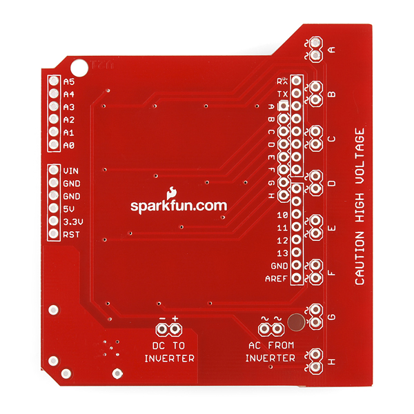
This board only uses digital 2-9 (and 10 to a status LED you could disable), all the other pins including the analogs are free for your use. See the schematic for details.
I don't know what connectors Adafruit uses; all of our EL products come with a 2-pin, 2mm JST connector. If you do need to adapt something else, we do sell the correct pigtails.
Awesome, those were the ones I was looking at. Thanks
i bought the EL Escudo Dos and the 12V inverter. however when i connect 12V to the arduino the EL wires/panels/tape are very dim. do i need to hook the 12V power supply directly to the inverter?
i was missing the S1 jumper. works great now.
Stackable please!
Can I stack 2 of these to control 16 EL wires independently?
The quick answer is no, though it could be done with a substantial amount of rework. On this board, the eight EL channels are hardwired to Arduino digital pins 2 through 9. You could cut the traces from those pins to the drivers, and rewire the drivers to listen to another set of pins (there's a header on the board to make this somewhat easier), but it would be a bit of work and not allow more than two boards total.
If people would like this capability, let us know and we'll consider a variant that allows you to stack as many boards as you wish (more or less).
You could use a Go-Between shield
What about this thing?
jau, stackable!
Forgive my lack of knowledge, but is any damage done to the inverter when all the wires are switched off? I was under the impression that you couldn't leave the inverter on (I'm using the 12v version) without causing damage.
That's a really good question. Since we don't know the answer either, I ran one of our 12V inverters overnight without anything plugged into it, and when I just plugged it back into an EL shield, it appears to work just fine. I don't know about long-term effects, but running it "dry" doesn't appear to cause any immediate damage.
Do these improvements mean that this shield is able to reliably change the intensity of the EL wire? I read a lot of comments on the EL sequencer that seemed to say that the triacs would only PWM for so long before dying. I have a EL sequencer and am scared of attempting to PWM the triacs for this reason.
Also, how long do you think it will be before your UK distributors have these in stock?
TL;DR: The new design solves the dying triac problem, at the expense of continuous dimming.
The old design couldn't enforce exactly when the AC could be switched on and off. This allowed continuous dimming, but because you could randomly switch in the middle of the AC waveform (where the voltages are largest), the parts could experience very large voltage transients. Not everyone had this issue, but a number of customers found that eventually these transients would kill the triacs.
The new design uses "zero-crossing" triacs, which means that if you turn them on or off, they will wait fractions of a millisecond until the AC waveform is at zero volts before switching. This makes everything electrically much quieter, and eliminates the possibility of damaging transients. We've found the board to be bulletproof in testing.
Unfortunately what you give up is continuous dimming - the triacs won't let you turn them on and off in fractional amounts, so you're limited to half-wave steps. We've found that you can still get several broad zones of stable dimming (say 6 or 8 steps from full-on to full-off), but intermediate PWM values will produce flickering (which is kind of cool too). The important thing is that you can't hurt the board by doing any of this, so feel free to experiment and let us know what you find.
Our distributors order from us on their own, so you should check with them directly to see when they'll have them in stock. Thanks and have fun!
Thanks for the quick and detailed reply. The 6 or 8 steps of dimming sounds like a good compromise if it's guarenteed not to damage the board. I'll hassle the UK distributors :-)
Also, is there any chance you'll update the EL sequencer to include these improvements? It's really nice having a self contained board with the Arduino already built in.
Yes, we're working on a revision of the Sequencer using the same circuitry. The board will end up being somewhat larger, but we think the improvements will be worth it. =)
Coolio! I look forward to it! How long do you think it will be before that is ready for sale? Sorry about all the questions. Have some applications in the pipeline and trying to work out what to buy / hold out for.
It's still early in the process; if everything goes well I'm guessing it will hit the storefront in October. But with the huge response to Makey Makey our production planning is somewhat in flux. In the meantime, the shield plus an Arduino is a good combo.
I bought the old sequencer. It really is terrible, and I'd like to get a newer one. Is there any sort of deal you can give me since the old product has so many issues? I would be willing to send the old board back, depending on the deal. It still 'works' (as much as one could say it ever worked) and none of the triacs are blown. You can contact me via email.
Thanks.
So what would happen if I cut the +HV traces so that I could hook up separate inverters to each or a pair of channels? As long as the grounds were all interconnected, would it work?
The idea is that I could power a whole lot more simultaneous strands of EL wire.
Crazy?
Sure it would work, but that's a lot of surgery to perform on this board. It might be easier to find a more powerful inverter, or design your own board (you're welcome to use our schematic to do so). I'll mention that our 12V inverter is pretty beefy and can handle numerous simultaneous wires, as long as they're not hundreds of feet long.