- Home
- Product Categories
- Kits
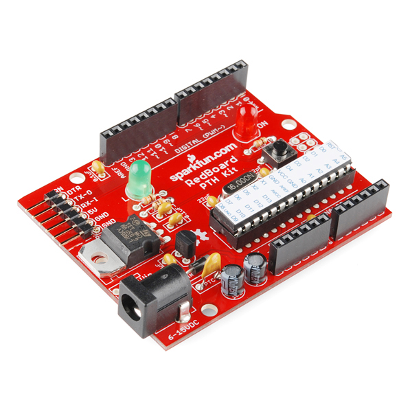
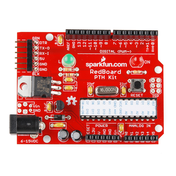
- SparkFun RedBoard - PTH Kit

SparkFun RedBoard - PTH Kit
This kit contains everything you need to build your very own Uno-compatible "RedBoard" development board! Simply follow the Assembly Guide and after some basic soldering, you'll have made a fully-functional Arduino-compatible development board (in fashionable SparkFun Red). The included ATmega328 comes pre-loaded with the "Optiboot" bootloader so you don't have to worry about loading the firmware, simply solder it together, connect an FTDI Basic and load your favorite sketch using the Arduino IDE.
After the board is assembled, it can be powered by an FTDI connection or a regulated 6-15VDC power supply connected to either the DC Barrel jack or the new JST footprint.
Note: You will need either an FTDI Basic or FTDI cable to load code using the Arduino IDE.
Replaces:DEV-10523
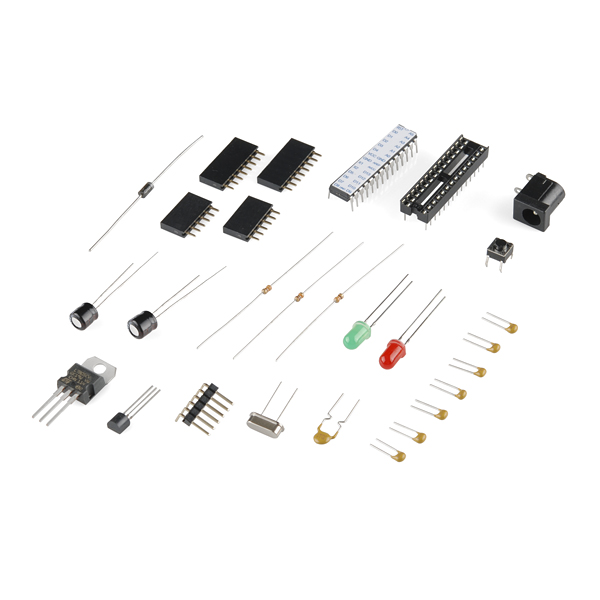
- 1 x Arduino-Compatible PTH Kit PCB
- 1 x ATMega328 with Optiboot bootloader
- 1 x MCP1700 3.3V Voltage Regulator
- 1 x 5mm Green LED
- 1 x 5mm Red LED
- 2 x 330Ohm Resistor
- 2 x 10kOhm Resistor
- 1 x 16MHz Crystal
- 2 x 22pF Ceramic Capacitors
- 5 x 0.1uF Ceramic Capacitors
- 2 x 10uF Electrolytic Capacitors
- 1 x LM7805 5V Regulator
- 1 x Diode 1N4001
- 1 x Resettable Fuse PTC
- 1 x 28-Pin DIP Socket (To seat your ATMega)
- 1 x Push Button Reset Switch
- 2 x 6-Pin Female Headers
- 2 x 8-Pin Female Headers
- 1 x 6-Pin Right Angle Header (To connect your FTDI Basic)
- 1 x 0.1uF Capacitor
- 1 x DC Barrel Jack
SparkFun RedBoard - PTH Kit Product Help and Resources
Core Skill: Soldering
This skill defines how difficult the soldering is on a particular product. It might be a couple simple solder joints, or require special reflow tools.
Skill Level: Rookie - The number of pins increases, and you will have to determine polarity of components and some of the components might be a bit trickier or close together. You might need solder wick or flux.
See all skill levels
Core Skill: Programming
If a board needs code or communicates somehow, you're going to need to know how to program or interface with it. The programming skill is all about communication and code.
Skill Level: Rookie - You will need a better fundamental understand of what code is, and how it works. You will be using beginner-level software and development tools like Arduino. You will be dealing directly with code, but numerous examples and libraries are available. Sensors or shields will communicate with serial or TTL.
See all skill levels
Core Skill: Electrical Prototyping
If it requires power, you need to know how much, what all the pins do, and how to hook it up. You may need to reference datasheets, schematics, and know the ins and outs of electronics.
Skill Level: Rookie - You may be required to know a bit more about the component, such as orientation, or how to hook it up, in addition to power requirements. You will need to understand polarized components.
See all skill levels
Comments
Looking for answers to technical questions?
We welcome your comments and suggestions below. However, if you are looking for solutions to technical questions please see our Technical Assistance page.
Customer Reviews
No reviews yet.
I think that I just saw an desing error, the 2 electrolytic capacitors are too high and you won't be able to put some shields on this
Good eye! That was definitely a problem on previous versions of these kits.
Luckily, it looks like we just put the wrong caps on the kit for the pictures. Those 100uF caps should be 10uF, and stubby 10uF's at that. So, they won't interfere with shields. We'll get the pics updated shortly.
Are you going to address the issue of the PTC's proximity to the capacitors which I mentioned here? You could address it by replacing it with a short or
They are indeed to high, but I expect that a future revision of the kit could easily correct this issue.
They're only 10uF 25V caps, many of these parts are available in 'stubby' format and are short enough to go under the shields. Here's a cap that would match these specs, or you can get a single 22uF cap which would replace both of these.
It appears that one could bend one of the capacitors over 90 degrees before soldering. The other one would hit the PTC, but if one didn't mind them touching, it could probably be made to fit.
That would make a bad design worse - When that PTC trips, it will get HOT. They're already too close; stacking them on top of each other would increase the problem.
Most PTCs trip at somewhere between 100 and 150 °C (200 to 300 °F). While this is much better than a 500 °C flame, and no big deal for the PTC or circuit board, it's far too much for the electrolytic capacitor. The cap is likely to boil over and fail.
Of course, it's unlikely that you'd leave your board unattended with the PTC tripped for a long time and your USB jack/wall wart/bench power supply likely has current limiting built in, but at that point you might as well replace the PTC with a wire to make room for the capacitors.
It does look like the capacitors are bit high. The shields might fit but won't be sitting in vary far. Might want to buy some extra tall headers just in case.
Why would you discontinue this?
They simply didn't sell well enough and we couldn't keep the manufacturing price low enough to keep them on the storefront. Also, this clears out space for other new and fun products!
I was going to make the following point when I first saw this product appear, but I was too lazy to login (yeah...). The point is made more legitimate by the comments about the design error that I failed to notice myself.
The Freeduino USB has been around at least a couple of years and has the FTDI chip included in the design. It costs only $23 from NKC Electronics and some other places.
There is also the "Diavolino" from Evil Mad Scientists Labs, which has less functionality than this Sparkfun product (doesn't come with the regulator, but will accept one). It only costs $13.
I love Sparkfun, but I tend to avoid buying things from you unless they are unique and useful because your prices are not always entirely reasonable. Either way, you people have done some great things (by merely existing) for the hobbytronics community. Just... stop proving my gripes correct, please!
Cheers!
This kit is/was an excellent learning tool for soldering and getting to know how an Arduino was made and put together. Learning about each component and its purpose and placement really gave you an understanding of microcontrollers and Arduino. Its a shame and a loss to see its been discontinued. I'm glad I bought 2 of the last 4 last week and will keep one in its box as a souvenir and memories. Thanks for making this kit Sparkfun and maybe a revival version some day hey!
Could I program this by taking the ATMega in this kit and putting in an uno?
Yes, if you don't have an FTDI board that should work just fine (assuming you don't have an SMD Uno)
Edited this comment because, in retrospect, I was upset over nothing.
Also, make sure if you are using an AVR programmer that you reinstall the bootloader before trying again over FTDI. Try the reset button and see if that works, but its likely an error with the FTDI board or bad soldering somewhere. If you are still having problems email techsupport@sparkfun.com and we'll see if we can come up with any other suggestions.
That's the infamous Arduino auto-reset capacitor, which is on most serially-programmed Arduino's (including Uno, and dating back to Diecimila).
When DTR goes from high-to-low, the cap should charge up, bringing the ATmega's reset pin low for just a short blip until the cap charges. That blip should all we need to reset the chip. So the action of DTR going from high to low causes the reset, rather than the line directly controlling reset. This allows the DTR line to act naturally, going low, and staying low, until data transmission has ended.
I've created a tutorial on how to connect this kit to a computer WITHOUT using an FTDI chip/cable. It costs about $3 CDN (less if you have components lying around). Can I post the link here?
Please do!
Yeah, my comment might have been a bit over-the-top. Was just very upset at the time. Now I understand better how SparkFun works -- I just wish that they'd say it a bit more clearly -- "We are for beginners only -- with the exception of a few products. Most other things can be bought cheaply elsewhere but that's not the point -- we're a one-stop-shop for people just getting into electronics who don't want to deal with element14, Mouser, Digikey etc which usually don't have exactly what you want as a beginner and also until you get used to their search functions can be overwhelming. Etc etc etc" Now I get it and am no longer upset about the prices here.
The big advantage of this kit to the preassembled board to me is the replaceable ATMega vs. the SMD version. If I accidentally fry the chip I can quickly swap it out.
Also, don't forget bulk SMD prices are cheaper than smaller quantity PTH parts. As for manufacturing, its not the products (the solder paste) that cost, its the man power, which is probably comparable to the manufacturing costs of our kitters putting everything together. Believe it or not our cost on the prebuilt board is actually a bit less then on this one.
The prices between the two are the same because of the manufacturing guide that was developed to go along with this kit. Print guides are unfortunately very expensive, even at bulk pricing. This kit is designed to be a learning tool for folks who are still improving their soldering skills and want to understand how each part of the board goes together.
Is there anything that is different about the way the included ATMega328P is set up that would make it different from the ATMega328P included on a standard Arduino? I was running into a problem and when I replaced the ATMega328P with a different one the problem went away. More details are here.
Why does this guy have twice as many caps as the breadboard kit?
I cant understand something .... if you do not have Arduino Uno can u operate and make applications for readboard (i mean can it stand by its own)!!!
There are no SDA & SCL pins on the upper-left pinheader. Why not add those?