- Home
- Product Categories
- LilyPad
- LilyPad MP3

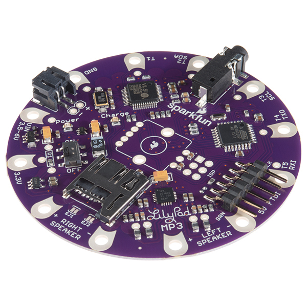
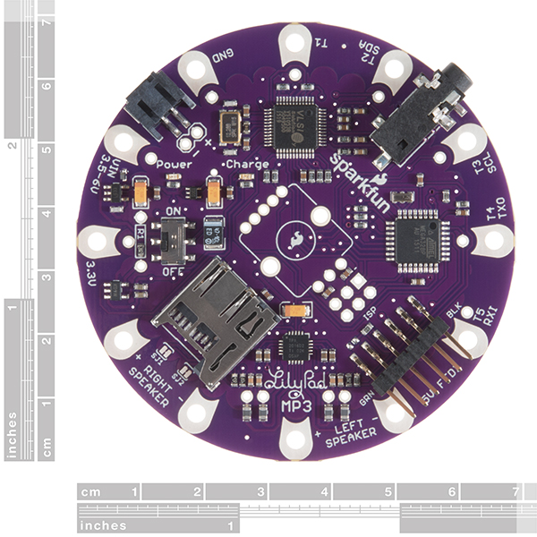
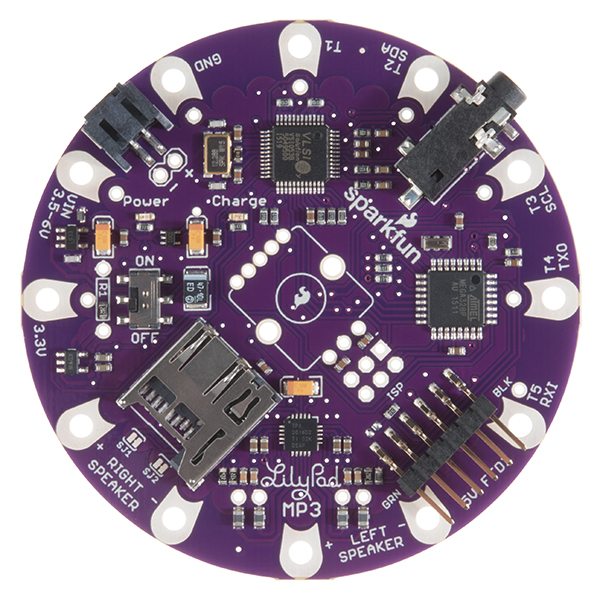
The LilyPad MP3 Player is your all-in-one audio solution, containing an Arduino-compatible microcontroller, MP3 (and many other formats) audio decoder chip, micro-SD card socket, and a stereo audio amplifier. Part of the Lilypad E-textiles line, this board can be used to give your fabric creations the gift of music, or any other sounds you can put on a micro-SD card.
It can be powered by a 3.7V Lipo battery (charging circuit built-in!), or an external 3.5-6V source. Off the shelf, it will play specific audio files when any of its five trigger inputs are grounded, or you can solder in an RGB rotary encoder (not included) and load new firmware (included in the link below) to add a user interface for track selection and volume control!
The board is compatible with sketches written for the MP3 Player Shield. Our example code uses Bill Porter's MP3 Player library, which makes writing new code very easy. All you need to do is add a microSD card and some speakers, and you're ready to rock.
Note: A portion of this sale is given back to Dr. Leah Buechley for continued development and education of e-textiles and also to Arduino LLC to help fund continued development of new tools and new IDE features.
- ATmega 328p microprocessor with Arduino bootloader (Pro 3.3V/8MHz)
- VS1053B MP3 (and many other formats) decoder chip
- TPA2016D2 stereo amplifier
- MCP73831 3.7V Lipo charger (preset to 500mA, rate can be changed if desired)
- Headphone jack
- Five trigger inputs, also usable as analog, serial and I2C ("Wire") connections
- Load new firmware (or write your own) using the free Arduino IDE
- 5V FTDI basic breakout for battery recharging and reprogramming
- Header for optional RGB rotary encoder (not included, requires soldering)
- Schematic
- Eagle Files
- Code/Examples
- User's Guide
- Datasheet (VS1053B)
- Datasheet (TPA2016D2)
- Datasheet (MCP73831T)
- GitHub Hardware Repo
- Product Video
LilyPad MP3 Product Help and Resources
Cackling Apple Head Witch
October 30, 2014
Make your own cackling apple head witch to scare all of the trick or treaters this Halloween!
Getting Started with the LilyPad MP3 Player
May 8, 2013
The LilyPad MP3 Player is an amazing little board that contains almost everything you need to play audio files. You can use it to create all kinds of noisy projects, from MP3 hoodies to talking teddy bears. Your imagination is the only limit! This tutorial will help you get started.
Resets or tracks that stop
If you see issues with resetting, or tracks unexpectedly cutting out, make sure the board either:
- has a battery plugged in or
- is being powered through either the JST jack or the + and - holes just behind it.
Both VIN and FTDI-VCC are tied into the battery charge circuit, and you can't source enough current through that to power the board. You can apply up to 6V at the battery jack.
Compile problems
If you're having issues compiling the code and see this error:
C:\Users\dxr1\Documents\Arduino\libraries\SFEMP3Shield\SFEMP3Shield.cpp:25:37: error: variable 'bitrate_table' must be const in order to be put into read-only section by means of '__attribute__((progmem))' PROGMEM uint16_t bitrate_table[15][6] = {
^
Error compiling.
It is due to the SFEMP3 Shield library. I recommend typing the word “const” in line 25 from:
PROGMEM uint16_t bitrate_table[ 15 ][ 6 ] = {
to
PROGMEM const uint16_t bitrate_table[ 15 ][ 6 ] = {
An alternative is to try downloading the the latest MP3 Player Shield library https://github.com/madsci1016/Sparkfun-MP3-Player-Shield-Arduino-Library/blob/master/SFEMP3Shield/SFEMP3Shield.cpp so that the Arduino can recognize the type array.
Delayed tracks
If your tracks are starting after a delay, make sure your MP3s have no wacky metadata in them. Especially troublesome is the album art that iTunes attaches to downloaded MP3s. You can strip the metadata from your tracks with an audio editor like Audacity.
Core Skill: Soldering
This skill defines how difficult the soldering is on a particular product. It might be a couple simple solder joints, or require special reflow tools.
Skill Level: Noob - Some basic soldering is required, but it is limited to a just a few pins, basic through-hole soldering, and couple (if any) polarized components. A basic soldering iron is all you should need.
See all skill levels
Core Skill: DIY
Whether it's for assembling a kit, hacking an enclosure, or creating your own parts; the DIY skill is all about knowing how to use tools and the techniques associated with them.
Skill Level: Noob - Basic assembly is required. You may need to provide your own basic tools like a screwdriver, hammer or scissors. Power tools or custom parts are not required. Instructions will be included and easy to follow. Sewing may be required, but only with included patterns.
See all skill levels
Core Skill: Programming
If a board needs code or communicates somehow, you're going to need to know how to program or interface with it. The programming skill is all about communication and code.
Skill Level: Rookie - You will need a better fundamental understand of what code is, and how it works. You will be using beginner-level software and development tools like Arduino. You will be dealing directly with code, but numerous examples and libraries are available. Sensors or shields will communicate with serial or TTL.
See all skill levels
Core Skill: Electrical Prototyping
If it requires power, you need to know how much, what all the pins do, and how to hook it up. You may need to reference datasheets, schematics, and know the ins and outs of electronics.
Skill Level: Noob - You don't need to reference a datasheet, but you will need to know basic power requirements.
See all skill levels
Comments
Looking for answers to technical questions?
We welcome your comments and suggestions below. However, if you are looking for solutions to technical questions please see our Technical Assistance page.
Customer Reviews
4.6 out of 5
Based on 5 ratings:
1 of 1 found this helpful:
Voice Alarm System
I am using the LilyPad MP3 for a custom alarm system. Instead of the usual siren, buzzer or bell, I am using a vocal warning and this device is perfect in this application.
1 of 1 found this helpful:
Very capable, oversized.
The LilyPad MP3 can play very loud through 8Ω speakers. Instead of remixing your tunes, you could re-program it to play softer, or add a resistor, variable or not, in line with your speaker(s).
Average batteries last very long. There are some voltage-level concerns with interfacing, but overall the power system is versatile enough for most applications.
I find myself wishing the board were smaller.
The 6-pin FTDI interface is fine for programming but awkward for everyday recharging. If I were to give this to someone, I'd solder on an FTDI basic so that the user was presented with a USB jack for charging.
1 of 1 found this helpful:
This little board met all my needs
This board has everything I was looking for. The headphone jack is super handy for prototyping before you wire up other speakers. I bought 4 of them. So far they have been very dependable.
Very Nice.
.So compact and easy to use
Everything needed for audio playback - but a few gotchas
This board has all you need to play audio. There are a few sketches out there to get up and running quickly. Two main issues I had - 1.) If you use a generic sketch for the SFEMP3Shield it will work for the headphones only. You must enable EN_GPIO1 for the TPA2016D2 amplifier chip to be turned on. It is not pulled high externally. This makes sense - you can disable the amp to save power / limit noise on the speakers but I spent a long time debugging trying to figure this out. 2.) I had a some issues trying to get the volume to a level which would not cause the board to reset. The speaker output can be quite loud but resets the uC if you don't have a battery plugged in. If you don't want to use a battery vin should be applied to battery input, in place of the battery.
Is there a Fritzing part for this board? Thanks
I think I burned the MCP73831T component (it started smoking and now it gets REALLY hot whenever I plug in battery and turn it on; the plastic got kind of warped; I think I may have somehow shorted it?). The rest of the board seems to be working just fine so I'm not sure how worried I should be. Is it normal for this piece to be super hot (maybe I just didn't notice it earlier?) and if this is a problem - do you know if it's possible for me to buy a new MCP73831T and solder it on myself, or is it time to give up and buy a new board? Thanks for your help.
Problems with I2C / SPI... Trying to adjust some settings in the TPA2016 amp by using the SFE_TPA2016D2 library. All functions return OK, but as soon as I try to start music playback, the sketch hangs. If I do not write anything to the amp, playback is AOK. I find this really weird, but have given up on this. Barely modified player.ino example file. Any tips on this?
Hi, I'm trying to read values from a voltage divider on the analog inputs. Works as intended on A0, but the values are somewhat off on A4 and A5. Could this be to do with the IC2 pullups? Should I try cutting SJ1 and SJ2? Sorry, if this is a dumb question, I'm pretty new to this all and trying to understand before I start hacking the hardware...Thanks!
To answer my own question...I just went for it and cut SJ2 and yes, it solved my troubles :-)
I would like to add sound reactive LEDs to the Lilypad mp3 project. I will play 4 songs and to every song should belong one set of 6 sound reactive LEDs. Is this feasible? Any idea is welcome. Thanks.
It's pretty hard to do sound-reactive LEDs with the LilyPad MP3. The Left and Right signals are piped to A6 and A7, but the processor really isn't fast enough to interpret the audio waveforms. The Spectrum Shield is a better option for frequency-based LED displays.
If you just want to have blinking LEDs, that's easy enough; just connect them to the Trigger pads and set them as outputs in your code. (The LilyPad MP3 is fully Arduino-compatible.) Good luck with your project!
2 questions. 1) is it possible to change the code to make to where as long as the board is powered it will for lack of better terms remember the last file played and play the next? what I want to do is put a couple songs on an SD card and using 1 trigger have the board play file 1 then on next trigger file 2 then on next trigger file 3 then on next trigger file 1 and so on.
2) is Sparkfun product number COM-09151 a good choice for this board
I would like to use it with 400mAh LiPo battery from Sparkfun. Do I need to change its resistor to prevent it from getting fire? Is it safe if I change nothing?
So if I use a battery ranging from 500mAh to 2000mAh I do not need to do anything with the resistor issues?
Thanks.
I've been using this lilypad for the last year or so for an art project. Since then I've updated my Arduino software. I went into my saved file of the "Trigger" sketch to adjust the volume, and now I am getting an error message. I get this error even when running the default files from the Code/Examples. I'm wondering if anyone else has gotten any errors lately with this board, or knows why it might suddenly not work. The error looks like this:
"variable 'bitrate_table' must be const in order to be put into read-only section by means of 'attribute((progmem))' PROGMEM uint16_t bitrate_table[15][6] = {"
None of this is anywhere in the examples, so I'm not sure why it's showing up. Unless it's an issue with the library.
Edit: It was an issue with the library, this link explains how to edit the library file so it works. https://github.com/madsci1016/Sparkfun-MP3-Player-Shield-Arduino-Library/issues/8
Hi folks, What's the ETA for new stock?
Hey! Question: What's the biggest micro sd card that the lilypad mp3 can take? 32 gb? 16? 8? I looked around, but couldn't find any questions regarding this, or in the user guide.
I really am looking forward to using this device, as I wish to have this to where I can make a velcro patch-on to fabric clothes and plush animals for on the go listening to music, or while i'm on the jumping stilts. Thanks!
Hi i an mew to using ardiuno and lilypad but what i would like to do is run approx 30 3v leds and control them (Just Fading) from the lilypad mp3. when i run them in series they are very dull but when i hook them up to a 9v battery they are the very bright. Is there anyway to do this? Thanks Nathan
Is there support for cross-fading between tracks?
The short answer: no.
Cross-fading has to be done after decoding. The VS1053 chip does the decoding and it does not implement cross-fading, so it is impossible to cross-fade MP3 or other encoded tracks. Cross-fading of .WAV tracks could in theory be implemented in software in your sketch, but it would require substantial software redesign because the existing software has only one file open at a time. On a full size computer you would do it by storing a few seconds worth of audio from one file in memory while reading the other, but an Arduino doesn't have nearly enough RAM to do that.
Hi All, I just got this board, and I'm firing it up with the a 5V input on VIN, and 2 files on the uSD card "1.mp3" and "2.mp3". They trigger properly when T1 or T2 are grounded. But, for some reason, playing the mp3 files seem to keep getting interrupted at various spots during play. It looks like the micro is being reset, because it is running setup() and loop() again after the playback is interrupted. The power supply is reading out a max of ~30mA, well within what it can suppply, so I wouldn't think it would be browning out. Could this be a hardware issue? Any ideas would be helpful! Thanks, Matt
Sorry about the problems you're having. The good news is that I know what's going on:
The board was really designed to run off a Lipo battery attached to the battery connector, with the VIN input (whether at the sewtap or FTDI pin) being used to charge that battery. If you try to power the board through the VIN pin, the battery charging chip will limit the current (this is it's job when charging a battery), leading to brownouts and resets as you've found.
The fix is pretty simple: if you want to power the board from an external supply, the easiest way to do so is to attach your supply directly to the battery connector or to the adjacent +/-headers. This bypasses the charge chip, sending current directly to the rest of the circuit, and there won't be any more brownouts.
If you want to modify the board to allow power through the VIN sewtap or FTDI port, you can solder a jumper from VIN to the + terminal of the battery. This will permanently bypass the charger, so don't plug a Lipo battery into the socket afterward as it may become overcharged by the unregulated VIN input.
I hope this helps, good luck with your project and let us know if you have further questions!
Can the analog pins on the LilyPad MP3 be addressed as outputs by the numbers above the digital ones? Ie. A0 = 14, A1 = 15 ... A7 = 21 ?
I have successfully switched a LED attached to A1 by calling digitalWrite(A1, HIGH), but do not have the same test opportunity on A6 and A7. I have attached a SPI device with its SS and RST to A6 and A7, and the library I try to use treats pins as integers - thus the need for addressing the analog pins by numbers instead of A0 etc.
As for now I have not made contact with the SPI-device, and wanted to be sure I am addressing the pins correctly.
Unfortunately you've run into an obscure detail of the ATmega 328 hardware; although the other analog pins can be used for digital I/O, A6 and A7 can only be used for analog input. This is a limitation of the internal hardware on the chip, and has nothing to do with the Arduino software. Sorry about that!
But all is not lost. The LilyPad MP3 Player does have the hardware SPI pins (D11,D12,D13) present on the 6-pin ISP header, and other pins are available on the RGB Encoder connector at the center of the board. The SPI pins are heavily used by the MP3 library to transfer audio data from the SD card to the MP3 decoder chip, but the MP3 library has functions that will let you use the SPI port between audio data transfers. See the "Hacking Tips" page of our tutorial for pointers, and good luck with your project!
Thanks for the quick and clearifying answer! :) I have already hooked my SPI device to the hardware pins, but need one for the SS line and was running out of outputs. Seems I will need to drop some other function of my project then. Thanks again!
I built a Halloween Scream box with LilyPad MP3 (LilyPad + PIR proximity sensor + mp3 of screams). I'm writing up an instructable. (It worked quite well: http://youtu.be/WhkZbyn9PVw)
Is there a Fritzing part for the LilyPad MP3?
Thanks!
Right now I am testing the Lilypad mp3 with headphones, but I wanted to change the volume of the L channel independently than that of the R channel (for starters)... Trying simple panning in here...
Thought it would be enough by placing different numbers within the code, say:
include <SPI.h> // To talk to the SD card and MP3 chip
include <SdFat.h> // SD card file system
include <SFEMP3Shield.h> // MP3 decoder chip
include <Wire.h> // to talk to the Amplifier chip
include <SFE_TPA2016D2.h>
(...)
MP3player.setVolume(5,30);
For some reason volume is kept the same in both headphones, as if one number will override the other? Why is this?
Should I use separated speakers (LEFT SPEAKER/RIGHT SPEAKER) directly from their terminals in this Lilypad board? Or is it that I am just not seeing something really obvious within the code?
Thanks!
Sorry you're having trouble with the board. I just tried it, and it works the way it is supposed to. Note that the volume control is logarithmic and larger numbers are quieter; try 10,100 and see if that doesn't show a difference (100 should be close to off). The other possibility is that if you're playing a mono file, it may be using the larger (smaller?) number. Let us know if you continue to have problems and we'll do our best to sort it out.
I bought this Lilypad and I'm trying to do a simple interrupt start&stop mp3 file. I use set HIGH/LOW to pin 3 (interrupt 1) and in callback I start or stop playing music. Everything works fine, but sometimes Arduino reset and setup() function executed again, restarting also the loop(). The code is the same of player example, but I have not button, but I trigger interrupt raising the pin 3.
I am interesting in using this board simply for its built-in SD card capability - in other words, I am not employing audio. I wish to be able to read data files off the card, formatted Fat32. And, I will be wanting to control RGB LEDs, including the timing-sensitive Neopixel style (WS2811/2812 chips) as well as the more timing-insensitive WS2801 types. Questions: 1) Has anyone used the SD card on this board for such a purpose, and if so, do you have an SD access library you recommend? 2) Has anyone used this board to control the timing-sensitive WS2811 chips? (I don't imagine this being a problem, unless something very specific to the design of this board and/or access to the SD card would prevent.) Thanks, David
If you don't need the audio decoding, why not use a dedicated SD card adapter. I've had success with this one from adafruit: http://www.adafruit.com/products/254
I am interested if it is possible to trigger several files than 5 – in terms of playing various random files by closing one switch on the board. So to say to have a bank of audio files for each inputs…? In case it is possible, I would appreciate a thorough explanation on what changes are necessary in the code, etc. (I am still a learner :) ) Also I would rather work with variable resistance / or capacitive touch than ordinary switches - and would be grateful for any tips!
Everything happens in software, so it's entirely possible to code up whatever you want. I can't give you the exact code you'll need (keep working at it, you'll get there), but here's a start: if you name all your sound files as e.g. "track009.mp3" there is a command in the library called playTrack(number) which will play that track number. You should be able to modify the trigger.ino sketch to play random tracks without too much work, just replace the playMP3() command with "playTrack(random(1,last track number plus one));". Note that we also have forums where people will be happy to help you out with this and your other questions. Good luck with your project!
Thanks for the reply - I will look at the changes in the code. It seems quite straightforward. Also I will post further questions to the forum. For now just to follow up on this thread, I am asking here: I might want to use several inputs than five, either capacitive sensing or variable resistance of some kind - what would be the best way of multiplying the inputs: by using several of the microcontrollers running individually or is there another way when using only one of the Lilypad MP3's...? Or would another microcontroller serve better? I am aiming for a no-computer setup, and also lipo batteries are a plus, as i want to avoid using power cords. and the running time is only 3 days, so i am thinking that a 2000mAh lipo would be fine...?
I would like to build a pressure activated 'mushroom'. When kids go and sit on the mushroom, it should play a predefined tune (e.g. the only track on the SD card) but when kids leave the mushroom, it should either stop playing or fade out the current mp3. When kids go and sit on the mushroom the entire show starts from scratch.
Now since these mushrooms will be placed in the playground; i have the following questions: 1) Is this the cheapest way to do this? 2) Is this the most power friendly way to do this (e.g. by supplying a 2000mAh battery, how long will it last? 3) Can i use an pressure pad attached to a trigger to accomodate my wishes?
I am a programmer by nature, but haven't done anything with Arduino before...
1) Hard to say. We carry several less expensive audio playback boards (1,2), but they would need additional hardware. The LilyPad MP3 has everything built-in.
2) Without sleep modes the LilyPad MP3 uses on the order of 30mA continuously. A 2000mAh battery will thus last 67 hours. You can improve on this by using sleep modes, but these aren't used in the demo software (you'd have to add that code, but there are tutorials out there that will help).
3) Yes! That would work great.
Good luck with your project, please send us some pictures when it's done!
Hi! I'm new at this, so maybe it's a silly question: What would be the code for an ON/OFF switch for the LilyPad MP3?
You mean to stop and start playback? If you're using the recommended library, it includes a number of commands such as "playMP3()", "stopTrack()", "pauseMusic()" and "resumeMusic()" that may do what you want.
Hi all,
I'm making an audio application in which I need to connect the Lilypad MP3 through Bluetooth with a smartphone. I'm using the Bluetooth Mate Silver connected to the FTDI port, but for some reason I'm no getting enough power out of the 3.3V pin of the FTDI. When measured with the multimeter I get around 0.5V. I check that the module is working by connecting it to an external power. I also realized that this pin of the FTDI is connected to the VIN pin. Is there any configuration that I need to change in the Lylipad? I'm using the 1000mAh LiPo battery. I was thinking on connecting the 3.3V out of the Lylipad to its own VIN, would this be an issue?
Any comments would be greatly appreciated.
The FTDI port on the LilyPad MP3 was set up to allow charging the LilyPad's Lipo battery, and programming the board with a 5V FTDI. Unfortunately this makes it difficult to use as a general-purpose FTDI port.
However, the GND, 3.3V, TXO and RXI lines you'd need for the bluetooth are available separately as sewtaps (each sewtap also has a single header associated with it), so you should be able to wire the bluetooth directly to the board. Note that you'll want to be able to disconnect the RXI line from the bluetooth while programming the board with the FTDI header, so don't make that a permanent connection.
Hello :-)
Im making this wearable circuit where I would like to use a few sensor (will describe it above) and Im wondering 1. If it would be posssible only with Lilypad MP3 or if it would need another Lilypad 2. How much power would it need and what would be the best battery for it (thinking about a LiPo 1000mA)
Sensors: 2 tpm36 (2analog pins) + 1 pulse sensor (1 analog pin) + 1 vibe board (1 digital pin) + 1 heating pad (1 digital pin + different battery font) + Sd card as datalogger. With this setup I would use all 5 pins availiable in the board, but dont know if Sd card needs to use any of those pins to be use as a datalogger. Also couldnt find how much power (v and amps) the Sd card takes.
Any thoughts about it? It will be greatly appreciated :-)
Hi all,
it seems that there is not overvoltage circuit protection, it is right? What's happend if I accidentally reverse battery voltage? It seems that the board will break irretrievably, beacuse I have not observed some diodos or some transistor for protect the circuit from overVoltage.
Another question is about battery recharge. It seems that the charge of the battery start as soon as 5V are give at the charger. How the charge is stop? It is a simple voltage comparison of power supply input? (less then 4.2Volt start charge, ugual or greater then 4.2Volt stop charge)? What's happend if my power supply is not battery, but a DC power supply? Will charger try to charge power supply?
Regards Francesco
You're correct, there is no overvoltage or reverse-voltage protection built into the circuitry. The board was designed to use our standard LiPo batteries and the 5V FTDI. If you use those, the voltage is correct, and there is little danger of plugging anything in backwards. You can of course use your own power supply, but you'll need to be careful to get the voltage (4.5 to 6V) and polarity correct.
Battery charging is handled by the MCP73831 chip, which monitors the battery voltage and stops charging when the battery reaches 4.2 volts (full) or above. The VIN and FTDI port connect to the input side of the charger. If you want to connect your own power supply, you should do it to the output/battery side of the charger (in which case the charger won't be active).
A simple way to connect external power to the board is to use a JST pigtail and connect to where the battery normally goes. The red and black wires are correct for power and ground, and the JST connector can't be plugged in backwards. If you have a 5V FTDI plugged in to program the board, the charger won't try to "charge your power supply" if your power supply is greater than 4.2V, because that looks like a full battery to the charger.
I hope this helps, let us know if you have other questions!
Could the MCP73831 chip be used to monitor for a low battery, or would another chip like the LTC4150 be necessary? I'm powering this with the PRT-00339 battery.
Really good question! The quick answer is that the MCP wouldn't be of much use. It does have a "charging" LED, but that only tells you if the battery isn't full, requires an external charging voltage to be present, and is not connected to the ATmega in any case.
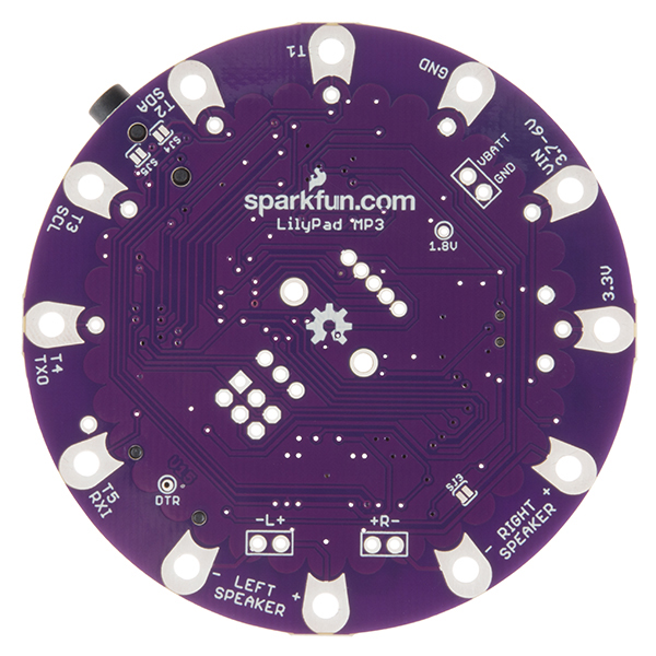
You could definitely use the LTC4150 Coulomb Counter to keep track of your battery. There isn't a free interrupt pin on the ATmega, but you could use the polling code and two (INT and CLR) or three (INT, CLR, POL) of the trigger sewtaps on the LilyPad MP3.
Another solution that preserves all your sewtaps would be to connect the battery voltage to a voltage divider (to lower the battery voltage below VCC so you can measure it), and running that to an analog input on the ATmega. The analog pins are all being used, but A6 and A7 are tied to the audio signals and aren't critical. You'd need to cut traces on the board and do some fine soldering.
Good luck, and this is a great suggestion for a future revision of the board, so thanks for asking!
I would like to cycle through many tracks with one button push. Is there a specific command in the library for this? So it would play track 1 on the first button push, stop that track and play the next track on the second button push and so on. Thanks!
The library can play tracks by name, but it doesn't include any functions to read the filenames included on an SD card. But we added this code to the "Player" sketch in the software repository above. This sketch was designed to switch to next and previous tracks (and change the volume) using the rotary encoder, but you can modify it to do the same thing for button presses. Check out the portion of the main loop that waits for a change in the rotary encoder and does the track-change operation. If you come up with a good piece of code, let us know and we'll add it to the examples!
Is it possible to add in a off-board push to make button?
Yes, that's actually what it's designed for! See the User's Guide above, particularly the "Getting started with the trigger sketch" page.
I don't think this was answered, but if it was and I missed it, I'm sorry. The FTDI needs to be 5v. Does it only have to be 5v out or does the signal logic level also have to be 5v? If this is a really dumb question, I'm sorry. I'm really new.
The logic signals should be 5V as well (there are voltage dividers on the board to bring them down to the 3.3V the processor uses). The reason we specify a 5V FTDI is to allow Lipo battery charging, which could not be done with a 3.3V FTDI.
The schematic for the pcb shows "left" and "right" being connected to pin A6 and A7 on the ATMega328. Are these the analog audio out pins being fed into ADC's on the mcu? Can anyone explain the purpose of this? Could I just cut these traces to utilize the pins for something else?
Since those pins were free (and can only be used for analog inputs due to the internals of the ATmega), we ran the audio signals to them with the idea that one could play with volume-meter effects in the software. I tried it and found that between the ATmega being relatively slow compared to audio waveforms, and busy much of the time transferring data, that my results were limited. They are unused in the demo software and not required for normal operation of the board, but they're available if you want to play with them, and maybe someone can come up with some neat effects. As it's your board (and open-source!) you can hack on it to your heart's content.
Anyone have experience getting this to work with neopixels and the neopixel library?
http://forums.adafruit.com/viewtopic.php?f=47&t=49652&sid=b25c884f199e753fbd64a2ff35b320e3
Ok so I noticed 2 more things different.
When I digitalWrite(pin, LOW) on lilypad trig1 the pin goes to about 2.4V and when I digitalWrite(pin, HIGH) the pin goes to 0. On the Flora, it's the opposite, and the pin voltage is higher too, about 3.4V.
I guess that explains why it doesn't work. Um, so now what? Thanks.
That's strange, we're not seeing that here. When we write trig1 low, we get 0V, and when we write it high, we get 3.3V as you'd expect. Here is the code we're using:
is it possible to connect this to the rn52 breakout ?
the schematics show pins 1, 2, and 48 of the vs1053b (mic-left/right inputs) not connected. visual inspection of the lilypad confirms. * is there any mechanical way to tap into these pins?
* i see there are testing points on the amplifier inputs . . . could i bring the rn52 in through these and carefully manage to turn off mp3 decoding when there is rn52 activity? would these two signal paths entering in parallel into the amp create problems? * i've built a very nice "background sounds" sculpture system that simulates the forest (lilypad mp3, 2000mwh lipo, light sensor, surface transducer, bird recordings, mounted in wooden "bricks"). These would be an ideal hands free platform that i would like to add the rn52 and be able to mediate between self generated background (lilypad's mp3) and the 2/way hfp or a2dp streaming received by the rn52 from iphone. any suggestions on how to get these two to work together?
The traditional (and pretty much only) way of tapping into pins that aren't broken out is to solder wire-wrap wire directly to the exposed pins on the chip. This takes some skill and magnification, but it's not impossible.
But before you do that, I'm not sure that the VS1053 is able to encode (record) and decode (play) at the same time. In other words, I don't think you can put audio on the mic pins and have it appear simultaneously at the output. (To be fair I haven't tried to do so, you'll need to refer heavily to the datasheet to see if it's possible).
You might be better off trying to mix the audio output of the VS1053 with the audio coming from the RN52. The LilyPad isn't really set up for this, but I'd probably take the audio out of the headphone jack (which will cut the audio lines to the amplifier), ground-reference the output from the VS1053 (info here), mix it with the ground-referenced output from the RN52 (google for schematics), and pipe it back to the LilyPad's amplifier. This still isn't overly straightforward.
If you're willing to reduce your options to audio files that are prerecorded on the SD card (8MB holds a lot of options), you could make a smartphone app that lets you select one of those options, then just send a text command across bluetooth to the LilyPad's serial port to select different local audio files.
Good luck, let us know what you come up with (and send pictures!)
What is an external power source that could be used with this? I'd like to have it permanently plugged in without worrying about recharging a lipo battery.
I may have found the answer to this on the hardware page.
… it looks like there's no simple "buy this external power source, it will plug in to a JST connector"?
HELP! There are two of us working with this board and nether of us can get the board to communicate to the Arduino IDE. The board selected is the one listed (Arduino pro etc Atmega 328) the Serial Port selected is the one that comes up when cable is plugged in. The libraries are in the right place. I have just been trying to troubleshoot by changing the trigger file debug section to true to print in the serial window. It mentioned that the board needs an external power source to load code that is there but both of us still get the error message : avrdude: stk500_recv(): programmer is not responding.
Any help would be amazing!
Hello, I am having the same problem with a board. A few days ago I successfully uploaded an altered version of the trigger sketch to a different board but am having no luck today. I have received the same message avrdude: stk500_recv(): programmer is not responding. Is this a problem with the board itself?
Sorry to hear you're having problems. First question: are you using a 5V FTDI board? (It was designed to use a 5V FTDI to allow battery charging; a 3.3V FTDI won't work). Also, as you noted, it should be externally powered and turned on to program it. (An attached Lipo battery is the easiest way). If you're still having problems, please contact our tech support department, who will be more than happy to help you out.
I have an oddball question: If I had multiple LilyPad MP3 units with matching SD cards and triggered them simultaneously, how much "drift" would there be in the playback start time from unit to unit? Would the offset be consistent each time the devices were triggered? And, if the offset could be measured and compensated for, would the playback (without external sync) stay together for a few minutes of playback time?
Okay, that was several questions...
Anybody done any experiments?
We've never tried this, but you can expect the oscillator components to be accurate to within a percent or so of their target frequency. This means that after 100 seconds of playback, two of these could be off by up to a second from each other. Each board will be fairly consistent, but note that temperature also affects the accuracy. This is a good example of a general class of problem where you need multiple systems to stay synchronized with each other, and the solutions can get pretty complex. (Sometimes it's easier to have a more powerful system do everything, since there is only one clock to deal with.) Good luck, let us know what you find, and how you solve it!
What I could really use is one of these with the VS1063 and a microphone input so I could record MP3s as well as playback.
I need one of these with a GPS so that I can program a sound track for real life, lol! Maybe clock and light sensor too! So many possibilities!
That's a great idea! (And fairly easy to implement, just pipe the GPS' TX line into the LilyPad's RX line, and use TinyGPS etc. to monitor how far away you are from various coordinates.) Let us know if you try it out!
I would like to trigger mp3's on a lilypad through a wireless (xbee) impuls. Is it possible to connect a lilypad-xbee directly to the lilypad mp3 and get it to work? Thanks
Sure! Just connect the TX on the XBee to the RX on the LilyPad MP3 Player, and write a sketch that listens for serial commands like '1' to play track 1. In fact, there's an example sketch in the included SFEMP3Shield library called "MP3Shield_Library_Demo" that may already do what you want. Let us know how it works!
THANK you so much!
Would it make sense to use a regular lilypad to handle the logic of sensor data, and then link to the mp3 lilypad for playback, especially if I wanted to have access to all 5 playback pins?
It depends a little bit on how much processing power your sensors require, but one neat thing about Bill Porter's MP3 library is that the audio data transfer takes place in the background via interrupt, so your "foreground" code is free to do other things like handle sensors. There are caveats around the fact that you need to be careful about sharing the SPI bus, and your code will be paused periodically by the data transfer, but it's worth trying on the single board first.
Yup! You can definitely do that.
I'm using windows 8 and hope to get the arduino app talking to the board. I've googled the error and it shows that arduino app isn't even making it to the board..
i have my board selected as "Arduino Pro or Pro Mini (3.3V, 8.MHZ) w/ ATmega328"
the USB COM port shows up, but i'm unable to upload the sketch to the board. It gives me an error:
avrdude: Version 5.11, compiled on Sep 2 2011 at 19:38:36 Copyright (c) 2000-2005 Brian Dean, http://www.bdmicro.com/ Copyright (c) 2007-2009 Joerg Wunsch
avrdude: Send: 0 [30] [20] avrdude: Send: 0 [30] [20] avrdude: Send: 0 [30] [20]
avrdude: stk500_getsync(): not in sync: resp=0x00
avrdude done. Thank you.
onboard Bluetooth? Disable your bluetooth adapter sometimes its uses the same COM port as the Arduino
I personally retreated back to Windows 7 due to all the problems with 8. If nobody replies here with good advice, email our tech support department, who should be able to help you.
Found the problem.. it was the FTDI cable.
I purchased FTDI Cable 5V (DEV-09718) and it only was providing power.
Luckily my friend had an extra and all worked well out of the box :).
I will be exchanging the cable via support.
Hi,
Is there any way to datalog the state of the triggers to the SD card in between playing the soundfiles? In other words, is there a way to halt the MP3 player, datalog then restart the MP3 player? Any advice would be greatly appreciated.
J
It's slightly tricky, but I don't see why not. Bill Porter's MP3 Library includes functions to pause and restart playback, and the SDfat library should let you have multiple files open at once. Bill's library also has the ability for you to perform brief SPI operations between audio data transfers, so you might not even need to pause the audio to do your logging. See the above web page and example code for more info. Good luck!
About this: "The LilyPad MP3 Player’s headphone jack is safe for headphones, but don’t connect it to an external amplifier unless you’re using a battery to power the LilyPad. (The fine print is that if the audio ground is shorted to the power ground, the audio decoder chip will be damaged)."
I'd like to use this in a non-clothing installation with powered speakers, but it's a wash if it has to be battery powered to work.
The VS10xx family uses a virtual ground for its audio output. If you connect the virtual ground (1.6V) to real ground (0V), an internal short will be created that WILL damage the chip.
You CAN connect the audio output (headphone jack) to a grounded audio input IF you do it through some inline protection circuitry. This application note has the details, and one of our customers put together a nice diagram of what you need to add on their website. Once you have this circuitry in place, you can safely connect the LilyPad MP3 Player to any amplifier, whether the LilyPad is battery powered or not. (And yes, this goes for the MP3 Shield, MP3 Trigger, and VS10XX breakout boards as well).
I hope this helps, if you have other questions let us know and good luck with your installation!
The schematic for this product already shows how this is done between the vs1053 and the amplifier. If you connect the L,R, and Gnd leads from the board to your external amplifier via capacitors (.1 to 1 uf, non-polarized) you should be fine. It's a DC connection between grounds that is fatal.
If you're using conductive thread instead of soldering wires, how do you connect the thread to the stripped wires on the speakers? Any suggestions/tips much appreciated!
We're looking into ways of making a LilyPad speaker module that you can sew to directly, but it's a hard problem to solve (for example the speaker needs to be able to survive the trip through our reflow oven). You might use a technique similar to this tutorial, which bends LED leads in a small circle to make it easier to sew to them. Ultimately you may need to do a little soldering to attach something to the speaker that you can sew to. Please let us know if you come up with any great ideas!
I have had good results using little snaps. Basically you solder to one of them, then sew the other one with conductive thread.
Check out this article on Adafruit: http://learn.adafruit.com/flora-snaps/overview
I have not used it with speakers, but I think it could be a good place to start.
Sorry for this newbie question, but can i attach any sensors to this? I want to run it with an accelerometer so that if you pick the project up it will react and play the sounds, but it seems to me all the I/O pins are taken for the sounds triggers. I know i can use a regural Arduino and MP3 shield, but my project needs to be small, battery operated and this seems perfect for it. Thanks in advance!
Great question! Take a look through the User's Guide linked above. There are five "trigger" pins, but two of them are also the I2C ("Wire library") port, and two of them are also the RX and TX of the hardware serial port. You also have access to the SPI port through the ISP programming header; the SPI bus is heavily used while playing audio, but if you're careful you can share it. Between all of these connections, you should be able to interface this board to many sensors. In fact, we're working on an update to the Elevator TARDIS project based on this board plus an I2C accelerometer. Have fun!
The only thing I'm trying to work out and it's a bit problematic is how to wash the hoody? Hand wasing it may be fine, but it may be a bit of a hassle. I'm trying to see if there is a way to make it removable. Like, sew some snaps on there. Also, the wiring down to the the sleeve, are the wires sewn in the sleeve? Would that be uncomfortable?
This is an AWESOME idea. It's exactly what I've been trying to build using the VS1003 and Arduino Pro Mini 3.3v (as separate boards). Unfortunately, it's too huge for what I need it for, but I'm glad to have your schematic so maybe I can make it smaller. This could make for some interesting ThinkGeek-like "instrument" t-shirts.
It's about the diameter of a Coke can, which was as small as we could make it without going to multiple PCB layers or double-sided construction which would have raised the price. If you can make it smaller by all means go for it!
It would be useful to have pinout information for the board itself apart from the 5 trigger pins at the board's perimeter. It's possible to map them out with the schematic, a datasheet for the LED rotary encoder, and the code examples, but it'd be nice to have that info easily available in the documents section above. This is an awesome product. Thanks :)
Glad you like it! Could you be more specific about what you'd like to know? We'll be happy to tell you, I'm just unsure of what more to provide than the schematic and the pin function table in the user's guide.
Basically having info on the pins that are located in the center of the board. It'd be nice info to have for those less technically inclined. For instance, A1 (aka pin 15) corresponds to the rotary encoder green LED pin, A3 (aka pin 17) is the rotary encoder B channel, pin 3 is the encoder's A channel, pin 4 is the encoder's switch pin, pin 5 is the blue LED on the encoder, and pin 10 is the red LED on the encoder. The reason I believe this is useful is because if you want to use more than the 5 "trigger" pins and don't want to use a rotary encoder. In a pinch, you could maybe also use the MOSI, MISO, and SCK pins in the ISP header area. To the untrained eye, it looks like there is only 5 pins available for use, when there may be as many as 14. Because the rotary encoder field isn't silkscreened, maybe provide a photo with some leader lines pointing out what Arduino pins these are. Just my two cents :)
Fair enough, I'll add this to the User Guide when we get back from Maker Faire. In the meantime, I strongly encourage installing and learning Eagle; it's perfect for answering questions like this, as you can click on a wire in the schematic and it will highlight the matching trace in the PCB view.
I'll note that although you can certainly use the SPI lines on the ICP header, those lines are used extensively by the firmware to move data between the SD card and the audio decoder chip. Bill Porter's MP3 Library does provide a mechanism for you to carefully use them between data transfers; see his web page for more info.
Good news, everyone! We've added a section identifying the rotary encoder and ISP pins to the User Guide, see the bottom of this page: https://learn.sparkfun.com/tutorials/getting-started-with-the-lilypad-mp3-player/hardware-details-and-hacking-tips. Thanks for the suggestion, let us know if you have other questions or comments, and have fun!
Can you program this with a 3.3v ftdi and run it with the battery?
Sadly no. There's a voltage divider on the FTDI to allow charging but prevent damage to the ATmega. If you give it 3.3V, the resulting voltage is too low to function properly.
I watched te product demo. Is all you need to make this wearable the Lilypad MP3, a microsd card that I can load music on from my mac, the rotary encoder and a couple of thin speakers, and thread to wire it?
you'd need a battery too as well. check the user's guide above.
Be sure to check out the User's Guide linked above, it has tons of information about the board and how to get started using it.
I'm curious how long this will last on a 2000mAh LiPo.
It will depend a lot on whether it is playing (and at what volume) or just sitting there, but I'd estimate over 40 hours.
What should the SD card have on it (besides mp3 files)? Does it need the patch files as described in Bill Porter's documentation?
Is there a way to access the MIDI capabilities of the VS1053B chip?
Followup Note: -The amplifier can really generate some volume, you may want to put a control on the amplifier ( e.g.: MP3player.setVolume(vol, vol) from a potentiometer on A0; Indeed, as the notes say, bigger speakers to generate bigger sound. I connected this to a pair of 6" automotive speakers and it is definitely loud enough for a 'room level' listening application.
We're happy that it's loud enough for you! That's a great idea to incorporate a volume control on A0. You can also change the default setVolume() value in the "trigger" sketch if it's not to your liking. Have fun!
Patch files are special files supported by the VS1053B that fix bugs on the chip and can provide additional capabilities. If you put patch files onto the SD card, Bill's library will automatically use them, but it doesn't require them to be there. We've tested it extensively without using patch files and haven't run into major issues.
The VS1053B chip will happily play .MID files straight off the SD card like any other audio file (note that only "format 0" files are supported). However, if you'd like to pass externally-generated serial MIDI data to the board, such as from a keyboard, you can close jumper SJ3 which will connect the RX pad directly to serial RX on the VS1053B.