- Home
- SparkFun LED RingCoder Breakout - RGB

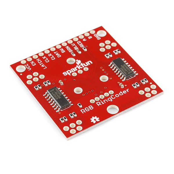
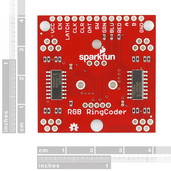
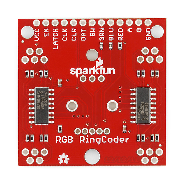
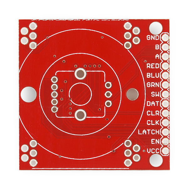
SparkFun LED RingCoder Breakout - RGB
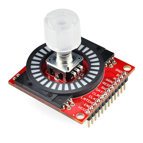
This breakout board gives you a pretty slick interface for rotary input. Since rotary encoders turn continuously it can be difficult to imagine where in your range of values you might be at any given time. This board uses two 8-bit shift registers to control a circular LED bargraph which can be used to indicate the virtual position of a rotary encoder. The footprint for the encoder matches up with our illuminated rotary encoders for optimum 'blinky-ness'. The shift register inputs and rotary encoder lines are all broken out to standard 0.1" headers.
This latest revision not only supports RGB, for our new RGB illuminated encoders, but also addresses several design problems that were brought up by customers in the last version. You can now safely run this board at 5V, so go build something awesome with it!
Note: This is the breakout board only, you will need to populate your own rotary encoder and circular LED bargraph. Both parts can be found in the related items below.
SparkFun LED RingCoder Breakout - RGB Product Help and Resources
Core Skill: Soldering
This skill defines how difficult the soldering is on a particular product. It might be a couple simple solder joints, or require special reflow tools.
Skill Level: Rookie - The number of pins increases, and you will have to determine polarity of components and some of the components might be a bit trickier or close together. You might need solder wick or flux.
See all skill levels
Core Skill: Programming
If a board needs code or communicates somehow, you're going to need to know how to program or interface with it. The programming skill is all about communication and code.
Skill Level: Rookie - You will need a better fundamental understand of what code is, and how it works. You will be using beginner-level software and development tools like Arduino. You will be dealing directly with code, but numerous examples and libraries are available. Sensors or shields will communicate with serial or TTL.
See all skill levels
Core Skill: Electrical Prototyping
If it requires power, you need to know how much, what all the pins do, and how to hook it up. You may need to reference datasheets, schematics, and know the ins and outs of electronics.
Skill Level: Rookie - You may be required to know a bit more about the component, such as orientation, or how to hook it up, in addition to power requirements. You will need to understand polarized components.
See all skill levels
Comments
Looking for answers to technical questions?
We welcome your comments and suggestions below. However, if you are looking for solutions to technical questions please see our Technical Assistance page.
Customer Reviews
No reviews yet.
Are there any alternatives to this?
Hi, is this pin compatible with the Rotary Encoder COM-09117 as I have them both? Thanks.
I'm sad to see this has been retired... it looks fantastic... you need to make a video of this in action and stick it on YouTube for our delight and delectation.
Can you get the RGB Circular LED Bargraphs shown here: http://www.youtube.com/watch?v=-3L8Nao3dus
They look like the same manufacturer as your https://www.sparkfun.com/products/10595
http://top-up.so-buy.com/front/bin/cglist.phtml?Category=325007
I think you'd be safe with those. The dimensions all look very similar, and they look to be common cathodes.
Well, they should be the exact same thing ;) I think rootScript is asking if you could add the 4 colors variant to the SparkFun catalog (next to the existing red, yellow, green and blue).
thanks Kamiquasi - Yes I would really like to get the multi color variant from Sparkfun, rather than just the single color. Can someone at Sparkfun see if they can source these little beauties, please?
The version of this board I received has solder jumpers which connect CLR to VCC and connect EN to GND. Is that a newer version of this product? If so, could we have an updated schematic and product photos?
Has anyone used this with teensy 3.1?
I have; and created a library for this break out (https://github.com/bettse/arduino_projects/tree/master/libraries/RingCoder) based (on PJRC's interrupt based encoder library (https://www.pjrc.com/teensy/td_libs_Encoder.html). You'll find a few projects using that same arduino_projects repo.
Has anyone used the board with the COM-10982 encoder and gotten weird results when using the RGB LEDs? With power and ground connected the board it looks like the 3 LEDs should light with their individual board pins grounded, but that is not the case for me. I can only get the blue and green pins to light when I apply 5v to the switch pin (and push the encoder push button) but even then the they are reversed and Red won't light at all. The schematic shows the push button pin 3 to be shorted directly to VCC when pressed so why would I get different results on the LEDs when using one or the other?
The example code doesn't work very well. It depends on "magic numbers" to get the quadrature encoder interrupt to fire correctly. I might rewrite it to get the bargraph to increment sequentially and predictably. Did anyone already do this?
Can this be used without the bargraph? I am just trying to do a prototype to start with.
Yep - though if you're just doing a prototype you may not need the breakout board, just the Rotary Encoder itself, as the breakout board is almost entirely for the purpose of interfacing between an encoder and the circular bar graph (and a few resistors for the rotary encoder's LED / pulling the switch low.).
I'm trying to use this as a wearable gadget and with about 0.5 meter of cable the shift register is seeing glitches (clocking on rising edge of data etc.) In the next rev of the board could you add some caps to provide better PS filtering to the board? I'm trying 1.0 - 4.7 uF tants and hope to improve the wire length to 1 meter.
And ... it's probably unnecessary to debounce the encoder (all you'll get is some bobble back and forth, but it will settle on the next increment), but is necessary to debounce the push button.
The example code says: oldEncoderState &= 0xC0; where it should probably say: oldEncoderState &= 0x0C; if the value of oldEncoderState is to stay within [0:15].
Perhaps a silly question, but with this using so many pins on the UNO how would I hook up an easydriver? Following the example pinout I'm left with 0,1,4. I've been told to avoid using 0,1.
Does anyone have Raspberry Pi Python sample code and wiring they would be willing to share? I'm just getting started and I'm finding the learning curve a bit daunting.
What part are you trying to use on the RPi? The rotary encoder, the LED, or the ring of LEDs?
I've started around the learning curve using several different pieces of code.
Im using ShiftPi from GitHub for the LED ring
The RGB LED and switch I've got figured out.
The rotary encoder is my only problem area. I found some code but the raspberry is running at full tilt checking for the change in state. And even then it misses or miss reads turns.
Here is where I got the Rotary encoder code from http://m0xpd.blogspot.co.uk/2013/01/rotary-encoders-on-rpi.html
Can this board just be used as a breakout board to a circular LED bargraph? IE. I don't have any need for the encoder. I just want access to the onboard shift register. Is this possible?
Thanks
Yep - check out the example code, you have the required access to the shift registers, the encoder portion is actually not wired directly to registers at all so you can pretty much ignore it.
Received this last night and really pleased with it. Word of caution though, when you insert the encoder, you will best to squeeze the grips a little with some pliers as you press down. I initially tried just pressing it and it caused the little grip thing to bend up upwards as there was too much friction. The good news is though that it sits very snug once in correctly. You could probably even get away without any solder!
if I use an Arduino mega, then which pins should I use, according to the Example Code?
5th pic is the older board (not RGB)
Be aware that this does not support the old RG encoders. The encoder portion will work, but not the illuminated handle. Although you CAN get the encoder into the board, one is common cathode and other is is common anode.
See it in Action
I'm not so sure 5V is a good idea for some applications. The schematic shows no limiting resistor from Vcc through the (closed) switch to the output. If connected to a device powered by a lesser voltage, a large current could flow through the input ESD protection diodes, and even drag up the lesser supply. Consider adding a series resistor and layout for easy user substitution. There is a trade-off between too low a resistance (fails to cure the problem) and too high (impossible to pulse a cleansing current through the switch).
I agree with your concerns. I'm going to be connecting this to a raspberry pi. I could power it from 3.3v, but I can't help feel this would be better if the switch was normally high impedance and went low when closed. We could then use an external pullup (or one built into the microcontroller). This would having to replace the encoder though with one with a common cathode.
Well that's my feedback sparkfun, hope somebody takes this seriously.
I wonder if there is an easy way to put a digital pot on here (without a microcontroller) and just make this the coolest potentiometer ever.
I mean even with an MCU it would be simple, but it seems like overkill.
The most straightforward way would seem to be converting the quadrature to discrete "up" and "down" pulses, and then pushing that into a digipot with an up/down interface, like the AD5220 or the DS1804 (among many others). http://www.edn.com/design/test-and-measurement/4347618/Rotary-encoder-mates-with-digital-potentiometer is an example using a quadrature decoder chip (the LS7084); http://electronicdesign.com/analog/simple-quadrature-decoder-suits-rotary-encoders has a decoder made from discrete logic if you wanted to go that route.
LSI used to make a quadrature-encoder controlled digipot, the LSXXXX. Alas, it's long gone now.