- Home
- Product Categories
- Switch
- Toggle Switch and Cover - Illuminated (Red)

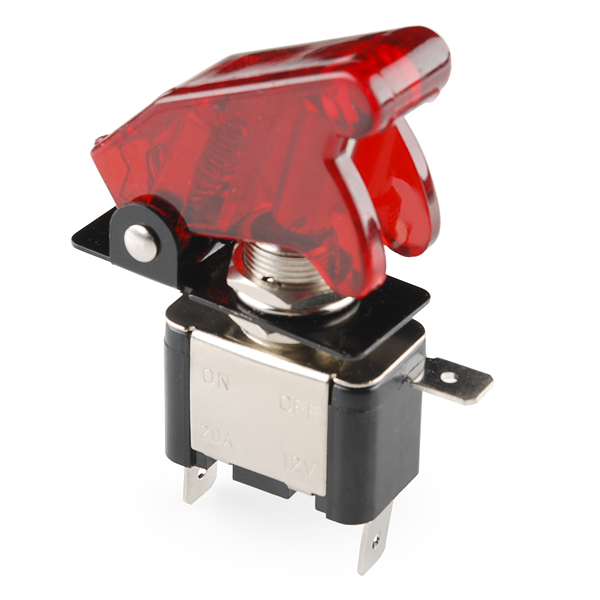
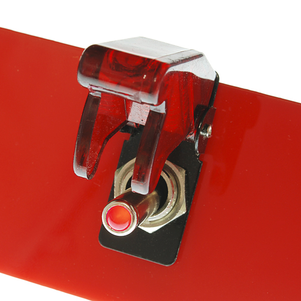
Toggle Switch and Cover - Illuminated (Red)
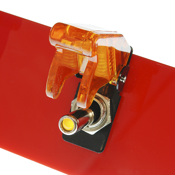
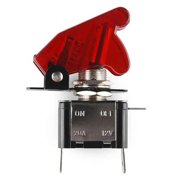
This simple on-off switch is rated for 20A at 12V but who cares about all that, it looks way awesome. These toggle switches come with those missile switch covers that make your project look like something out of a spy movie. They're also a great safety feature to ensure that you don't accidentally fire the missiles (or whatever it is your switch does). As if you needed any more convincing, they're also illuminated with a small LED in the end of the switch. These can be panel mounted into a 12mm hole.
Check the related items below for more color options!
Note: The LED can be illuminated with as low as 3.3V.
- Rated for 12V 20A
- Includes Missile Switch Cover
- Illuminated
Toggle Switch and Cover - Illuminated (Red) Product Help and Resources
Core Skill: DIY
Whether it's for assembling a kit, hacking an enclosure, or creating your own parts; the DIY skill is all about knowing how to use tools and the techniques associated with them.
Skill Level: Noob - Basic assembly is required. You may need to provide your own basic tools like a screwdriver, hammer or scissors. Power tools or custom parts are not required. Instructions will be included and easy to follow. Sewing may be required, but only with included patterns.
See all skill levels
Core Skill: Electrical Prototyping
If it requires power, you need to know how much, what all the pins do, and how to hook it up. You may need to reference datasheets, schematics, and know the ins and outs of electronics.
Skill Level: Noob - You don't need to reference a datasheet, but you will need to know basic power requirements.
See all skill levels
Comments
Looking for answers to technical questions?
We welcome your comments and suggestions below. However, if you are looking for solutions to technical questions please see our Technical Assistance page.
Customer Reviews
4.1 out of 5
Based on 7 ratings:
1 of 1 found this helpful:
Nearly perfect!
Would be perfect if LED could be controlled independently. Currently, the LED is always on if the switch is closed.
Side note: Adafruit appears to carry the exact same switch, but also has more colours. I'd love to see those available here too!
3 of 3 found this helpful:
A Classic Switch
These switches warranted my purchase because of their classic toggle styling and LED lighting. The spring is much stronger than I expected, but it makes for a quick and easy off toggle. I measured the voltage drop across the LED as 1.9V, and it had that same voltage drop across each positive connection. I accidentally wired my first one up without enough current limiting resistance and burned out the LED, but it still looks gorgeous. I did not find a competing product that was this inexpensive in my short search.
3 of 3 found this helpful:
Nice Pictures - No Documentation
I have no doubt that I will figure out the wiring configuration for the LED, but it shouldn't have to be this way. I see that someone else killed his, and it isn't hard to figure out why... I am glad I bought two -- hopefully, I will get one to work. FWIW, It is virtually impossible to safely illuminate an LED without knowing the forward voltage, and the current. Documentation that reads "The LED can be illuminated with as low as 3.3V" is of absolutely no value...
There are 3 connection points. Apply voltage (12V) to the +. Apply ground to the Ground symbol. The third pin is your output pin for when the toggle is active.
These are generally used in automotive applications (12V) however, they can be used in other applications, hence the note about how low the LED will operate.
2 of 2 found this helpful:
Epic switch, everyone loves it.
What I like most about this switch is the SOLID spring on the cover, feels like something that will last. The illumination and cover is what made me look for a great project to put this in, it sat in the drawer of switches for a while before finally everyone said "This is the switch we must use"
6 of 6 found this helpful:
Dim LED
There are about 700 Ω in series with the LED, so it's not very bright at 3.3 V. It's really meant to be driven at 12 V with no external series resistor. Still, physically it's pretty great. I just wish it didn't have any internal resistor.
1 of 1 found this helpful:
Good switches
They are solidly built and great for all your missile launch needs :-)
The internal wiring took a little figuring out so I posted a schematic of them here for your viewing pleasure: https://www.lee.org/blog/2014/08/06/sparkfun-illuminated-switch-schematic/
Great looking switches
I got them to install in my wrx to control stuff like my gauges, radar detector, etc just for fun. I threw them under my head unit and they look awesome.
Switch appears to be leaking about 1.5 volt when in the OFF position. What's up with that?
USB 5V power source to + connector. Switched output on the LAMP connector. Ground on the Ground connector. The LED in the toggle switch behaves as expected.
These are a bit annoying to wire up correctly. As Member #246694 notes, there are only 3 pins but the pin with the ground symbol is not the common pin -- it is only connected to the LED. The pin with the plus on it and the LED pin are connected together when the switch is closed.
This means that if you want to control the LED and check the switch position independently, you need to wire it up like this:
Also add a 10K ohm pull-down resistor between the input pin and ground on the Arduino. The Arduino's internal resistors are pull-up and that won't work here so we need to do this manually.
Now to turn the LED on, set the output pin LOW (so current flows from +5V through the LED and to this output pin). To turn it off, set the output pin HIGH (so current cannot go anywhere). Yes, that feels backwards.
The input pin will be HIGH when closed (as it is connected to 5V), and LOW when open.
For anyone who might have trouble figuring out how to wire this switch, I drew a schematic of how to wire it up. http://www.lee.org/blog/2014/08/06/sparkfun-illuminated-switch-schematic/
Thanks for writing this! I was having quite a bit of trouble with this switch until I read this. I wrote a little sample code to go with your comment. It will blink the switch LED, and also turn on/off another LED using a third pin when the switch is toggled. I thought it might help others. In addition to your wiring listed above another LED will need to be hooked up to another output pin. // define pin constants #define SW_LED_PIN 2 #define SW_IO_PIN 3 #define OUT_LED_PIN 4
EDIT: Added some documentation... shame on me for posting code without
I'll just leave this here
How could I do this but with +12V connected to the LED lead?
There are 3 terminals on this switch. Here is how I hooked it up for 12v power application (on-off switch for a battery)
Ground- 470 ohm resistor to limit LED current. +- Battery Positive. LED-Supply voltage for circuit.
The LED on the switch only comes on when the switch is in the ON position. If you want it illuminated whenever the battery is connected, swap the connections to + and LED.
Are the switch load contacts and the LED control contacts separate (4 terminal), or do they share a common ground lug (3 terminal)? Can't tell from the description or pictures. Makes a HUGE difference.
If they share a ground (3 terminals) then you're good to go for DC only projects.
If the load contacts and LED contacts are separate (4 terminals) then you can control AC loads with the switch contacts and control the LED separately.
Someone can correct me if I'm wrong, but from what I could see in the video (friday new products) it's a common ground lug.
Correct! There are only three contacts, with a common ground.
Actually, I'd think a lot of people would care about the ratings. These switchs can withstand four times the current (albeit at a somewhat low voltage) your regular SPST toggles can! Any chance they have ratings for other voltages, like 50V, 125V, or 250V?
I believe it was a joke.
Of course it was a joke.:p However, the current ratings at other voltages would be nice, if available. In the case of switches, there aren't simple but relatively accurate ways to extrapolate or derate values because the mechanical construction can vary quite a bit.
The little drawings are confusing, but it kind of makes sense if you think about them for an always-on LED. Remember that you're never actually connecting directly to both positive and ground of your voltage source -- that would just be a short! You're usually interrupting the positive line to a device.
Think about the pinout this way:
Will the LED be always on, or does it come on when the switch is turned on? Do I need to provide a resistor for the LED or is that handled within the switch?
There are 3 terminals on this switch. Here is how I hooked it up for 12v power application (on-off switch for a battery)
Ground- 470 ohm resistor to limit LED current. +- Battery Positive. LED-Supply voltage for circuit.
The LED on the switch only comes on when the switch is in the ON position. If you want it illuminated whenever the battery is connected, swap the connections to + and LED.
Does the led need resister
Does any one have some arduino code for using the led sprats for the switch as a input.
any one answer
Can I get some with a sensor in the lid so I know when it's open?
We don't sell any like that, but you could add in a reed switch or flex sensor to tell you.
Hi I want to put these in my 98 jeep cherokee sport, I'm thinking about switching out my rear defrost, rear wipers, and my fog lights for these switches. I need more help trying to figure out if they will fit or if they won't, so can anyone help me, also I need to know how I to wire them up, if I get them?
I have the same vehicle. If you're planning on just putting these on the front of the dash, they should fit just fine. If you're thinking about embedding them somehow, then it's going to get a bit more complicated.
Great switch! But when I ordered I made the mistake of thinking this was mostly for novelty, it's actually quite heavy duty and 'clunky' for lack of a better word. It's super cool and I'm glad I bought one, but it does take a bit of effort to move from one position to the other. If you know that going in it's great!
When the switch is actuated, can the cover almost act as an emergency OFF! switch by slapping it down?
EDIT: Just read shardbearer’s comment.
Thats great.
this would be cool with that light pipe you guys sell!
Simple. The (+) and the (-) from 9vdc power supply to the (+) and (ground) on the switch. And the (- ground) from switch to board or whatever. Since the ground and led illuminate pins are always connected, then you would wire the LED illuminate symbol (+) to the board or whatever you are powering. Switch off = no led. Switch on = led lit. Led will only get power and light when the board or whatever you are powering is on.
From PS (+) ---> To Switch (+)
From PS (-) ---> To Switch (- ground)--> Also jumped from switch to (-) on board or whatever
To Board (or whatever)
Does this switch turn off when you close the cover?
yes
It would be REALLY helpful to have a product spec sheet for these switches with both mechanical and electrical information. I have 8 of these (in various colors) and the LEDs have burned out in most of them -- running with the specified 12VDC max.
Are the LEDs not rated to take 12v? It would be good to state that somewhere -- somewhere that is easy to find (not buried 25 comments down in one of 9 product pages, or in an unconnected forum).
I bought these for a pyrotechnics rig where the LEDs are supposed to give feedback for LIVE. Unfortunately that wont happen now. (it did look cool for a while with flashing leds as associated lines were flashed under arduino/midi control.)
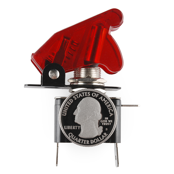
What are the physical Measurement for this switch ?
need some help with wiring it. i got 3 from here and i tried to wired it to a 9v battery but the led on the toggle wasnt lid what am i missing?
I have been bewildered as well, any schematics or tutorials out there? Rather disappointed I can't make my doomsday device.
One side has a ground symbol, plus sign, and an symbol with rays coming out of a half circle (LED positive). If you connect ground to the ground contact, and positive to the LED positive contact it will illuminate. When you flip the switch the plus sign and the LED positive are connected.
Actually the LED positive is always connected (even with the switch in OFF mode)
Mine does not work that way. The LED pin and the (+) pin are connected only when the switch is ON. Perhaps yours is defective?
Try reversing polarity.
That always works in the movies.
Actually it does work. The LED setup is a little odd to me in that you provide a ground for LED instead of an LED power pin. I'm currently wiring one of these switches to my PC power supply converted to bench supply and the way to go was to wire the green "on" wire to the + symbol, the ground to the 'lamp' symbol, and -12v to the LED ground. That way, when you close the switch, green gets connected to ground, and the power supply turns on and provides -12v to the LED ground and it lights up.
So if you are going to use this as a low-side switch you will need to come up with a negative voltage to drive the LED. Question about this: is there any danger of going above 12v on the LED from the load being switched to ground "raising the ground"???
If you are using this as a high-side switch (as obviously intended), then you simply put your load on the 'lamp' symbol, your positive voltage on the + symbol, and ground on the LED ground, and it should do the same thing and light up when switched on only.
It be cool if you could rig a model rocket to it and the put it out in public and see how many people would flip the switch.
Any idea when these will be back in stock???
Please check back around the mid of July! :)
Can we get a picture or demo video of all the colors while illuminated? Maybe a day/night comparison too?
Does the LED need a resistor in series?
Only if your running it at a higher voltage than 12V I think
Correct, you should not need a resistor unless powering beyond the intended 12V rating. Thanks