- Home
- Product Categories
- Signal Generators
- Frequency Generator Kit - FG085


Frequency Generator Kit - FG085
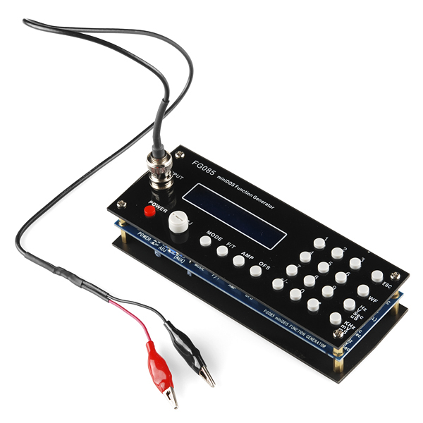
Function generators are useful in a ton of applications from RF to embedded logic. They're not usually super cheap though. Good news: we found a kit. The FG085 MiniDDS Function Generator is a 'some assembly required' kit that becomes a flexible, functional and easy to use frequency generator. Just solder the through-hole parts in place, attach the face/base plates and before you know it you'll be generating sinewaves at frequencies up to 200KHz! But that's only one of the tricks this thing can do. Three different operating modes allow the FG085 to generate 7 different types of continuous waveform as well as servo test and control signals in micro-second resolution.
The LCD screen and menu system make this an easy instrument to operate. Frequency, amplitude and offsets can all be set with the number pad and incrementally adjusted with the rotary encoder. The incremental step size can even be adjusted to make sweeps over a wide range easier to handle. The FG805 can generate a peak to peak amplitude up to 10V with an offset range from -5 to +5VDC. It can even be used as an adjustable DC voltage source by setting the amplitude to 0.
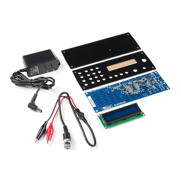
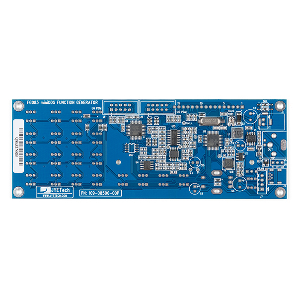
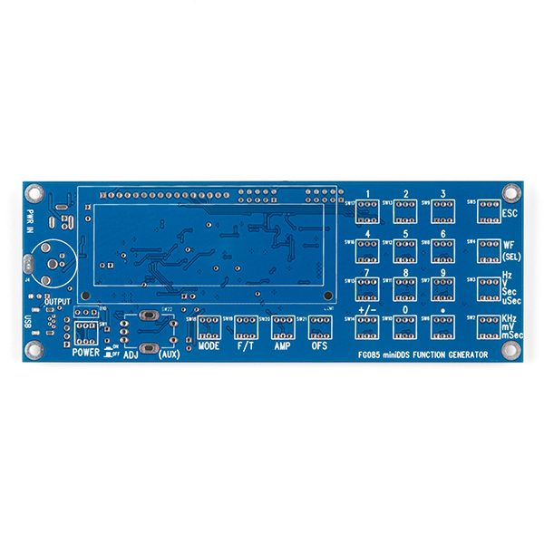
- FG085 miniDDS Function Generator PCB with SMT parts installed
- Acrylic Faceplate and Baseplate
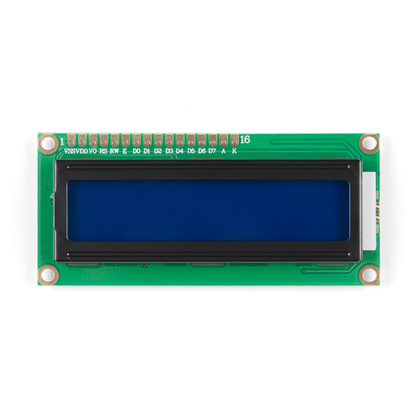
- Alphanumeric LCD and Headers
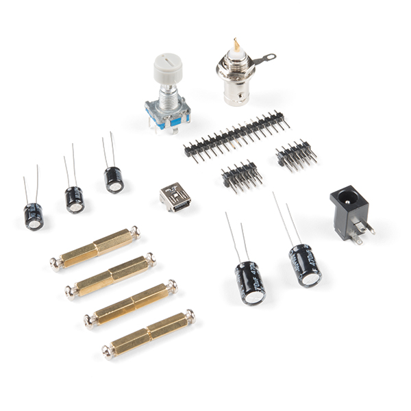
- Through-hole Parts Bag
- 15VDC 1A Wall-wart Power Adapter
- Quickstart Assembly Guide
- Output cable (BNC + clips)
- Generates continuous waveforms of Sine, Square, Triangle, Ramp (up and down), and Staircase (up and down)
- Generates servo test/control signals in micro-second resolution with user programmable pulse width, amplitude, and cycle
- Set the frequency (or period), amplitude, and offset with number pad - quick and straight-forward
- Frequency (period), amplitude, and offset can be incrementally adjusted with rotary encoder
- Settings are memorized after power down
- Can be used as an adjustable DC voltage source by setting amplitude to 0
- Frequency range: 0 - 200KHz (Sine)
- Frequency resolution: 1Hz
- Period resolution: 1ms
- Amplitude range: 0 - 10V peak-to-peak
- Offset range: -5V - +5V
- Memory depth: 256 bytes
- Sample rate: 2.5Msps
- Output impedance: 50 ohm
- Power supply voltage: DC 15V
- Current consumption: < 150mA (without loading)
- Dimension: 155 X 55 X 30 mm
- Net weight: 100 gram
Frequency Generator Kit - FG085 Product Help and Resources
Magnetic Levitation
November 20, 2019
This tutorial will show you how to build a magnetic levitation circuit using common parts.
Common Assembly Issues
If you have a blinking/flashing LCD display, it's most likely a bad power supply or a short circuit somewhere in your soldering. Double check your solder joints and verify that you have a stable 15 volt output on the power supply.
Core Skill: Soldering
This skill defines how difficult the soldering is on a particular product. It might be a couple simple solder joints, or require special reflow tools.
Skill Level: Rookie - The number of pins increases, and you will have to determine polarity of components and some of the components might be a bit trickier or close together. You might need solder wick or flux.
See all skill levels
Core Skill: DIY
Whether it's for assembling a kit, hacking an enclosure, or creating your own parts; the DIY skill is all about knowing how to use tools and the techniques associated with them.
Skill Level: Noob - Basic assembly is required. You may need to provide your own basic tools like a screwdriver, hammer or scissors. Power tools or custom parts are not required. Instructions will be included and easy to follow. Sewing may be required, but only with included patterns.
See all skill levels
Core Skill: Electrical Prototyping
If it requires power, you need to know how much, what all the pins do, and how to hook it up. You may need to reference datasheets, schematics, and know the ins and outs of electronics.
Skill Level: Rookie - You may be required to know a bit more about the component, such as orientation, or how to hook it up, in addition to power requirements. You will need to understand polarized components.
See all skill levels
Comments
Looking for answers to technical questions?
We welcome your comments and suggestions below. However, if you are looking for solutions to technical questions please see our Technical Assistance page.
Customer Reviews
4.1 out of 5
Based on 34 ratings:
1 of 1 found this helpful:
Fun to assemble but noisy, inaccurate output
The kit went together easily in about 30-40 minutes.
The DDS firmware on the kit I received is a revision old. The latest is 113-08502-053 which fixes a bug with frequencies less than 40Hz (see the product page link below).
As Member #207448 already mentioned, the output is extremely noisy at line-level voltage and essentially useless for audio applications.
Frequency is pretty much bang on.
And lastly, be wary of the indicated amplitude. I took some sample measurements on my Rigol DS1074Z with a 10kHz square wave:
Indicated: 0.1V - Measured: 260mVpp
Indicated: 1.0V - Measured: 1.20Vpp
Indicated: 3.3V - Measured: 3.60Vpp
Indicated: 5.0V - Measured: 5.4Vpp
Overall, a good and fun kit but I was hoping to get better performance for audio amplitude and frequency ranges.
2 of 2 found this helpful:
Perfect and flexible kit
I found more to this kit than what was directly represented on the order page. Designed/Manufacturerd by JYE, their web site opens the door for additional information and provide a path for firmware upgrades, newer user manual, and their JyeLab software; which allows for constructing your own waveform for uploading to the device.
Great for learning to use an oscilloscope, testing and establishing duty cycle for servo motors, or playing around as in the SparkFun Video.
Assembly was easy with the visual guide, but it is is not for the beginner. Soldering points are fine, thus good soldering skills recommended.
Takes some getting use to how it works; checking JYE for a more recent user manual was what I needed. Per heaps after this post SparkFun will download to their page.
For me as a beginner to the use of generated frequencies, I have found this a excellent versital platform for learning and long term project use. Other options exist on the market, but for the price and added joy of self assembly, this is perfect for me.
Your excitement may vary!
4 of 4 found this helpful:
Noisy
Nice kit, easy to assemble if instructions are carefully followed. It is well designed and easy to use.
Two problems though: (a) the BNC connector on the output cable is too tight and doesn't fit the output plug (!) this was not an issue for me because other cables I had work well, but this may be a problem for others and (b) the output signal is extremely noisy and not really suitable for many analog applications.
3 of 3 found this helpful:
Great product
I bought this to help my oldest son with a science fair project. We needed to generate specific frequencies to be pumped into a rubens tube for sound wave measurement. As a bonus I was able to teach him a bit about oscilloscopes when I checked the accuracy of the generator (which by the way was dead on). All in all a very nice little product, well packaged, and fairly easy to assemble. Good project for a beginner that is wanting to try out a build and challenge themselves. One note, the ground leg for the output connector is a hair too short to reach the board, and the instructions say to cut it off and solder in a piece of wire as a replacement. I opted to keep the leg, and make a pair of J shaped hooks to drop in and act as a bridge to the board. I felt that it gave a much sturdier connection that wouldn't break if there happened to be any pressure applied.
1 of 1 found this helpful:
Very nice !
Simple to assemble, it works very well !!! Perhaps white noise can be added ...
A good prototype
The function generator works (sort of), but there are a lot of things that should have been fixed before they started selling these.
I have a detailed review (with plots) at https://gasstationwithoutpumps.wordpress.com/2015/07/16/fg085-function-generator-bugs/
Great Generator, for the price very impressive .
Very pleased with it. I would like a cabinet or case for it. Would be nice if one was available. Even one made out of heavy cardboard would be very helpful. --- I plan on making one with cardboard and some tape. Put in a chunk of metal for weight, and it will be much handier and usable, for me anyway.
A mighty fine piece for a reasonable price
Easy to build from their good directions, this unit has quality parts. Everything fit, everything worked first time. Very versatile, and has many functions. Fairly quick to learn how to access the different functions and parameters. The price is NICE.
nice, inexpensive...very happy with it
Took about an hour or so to build the kit...i worked slow so that everything would line up with the faceplates on final assembly, which it did. At first, upon power on, it was giving a "f/t step ________" config screen and not the correct jyetech splash screen...after a few reboots / power resets, it just started to work correctly and continues to do so, so all's well that ends well i gues...
Great little kit
If nothing else, soldering this brought me to realize how lame my soldering iron was and how much I needed a new one. But in fact, that wasn't all.
The interface is a little strange, but easy to use if you read the manual. The rotary encoder is a little slow to respond, so be patient with that.
There are 4 modes: - Single frequency - Sweep range of frequencies - Servo single position - Servo run (sweep range of duty cycles)
Another interesting feature is the wave forms. It comes with sine, square, triangle, ramp (both directions), staircase (both directions), and user defined. Yep. You can define your own wave form and upload it via the USB port. I haven't done so at the time of this review, but JYE Tech has good documentation on their website and forum.
While this device is not completely open source, there is a schematic available on their website.
After assembling it I hooked it up to a speaker to demonstrate it to my family. I highly recommend driving a powered subwoofer with this. (start with 200 mV and work your way up)
Nice Little Unit.
Good little Function Generator. Works well. Micro tends to hang up every once in a while. Good clean waveform. Instructions on placing the pushbutton switches should be explained better.
0 of 2 found this helpful:
Horrible experiaence
I have got this unit in un assembled condition....this was not mentioned anywhere while ordering. please advice to return it back.
Hi, This is labeled a kit, and has instructions for assembly in the description. I apologize that this was not clearer that this is an assembly required kit. Directions for return can be found here https://www.sparkfun.com/returns
Excellent
Easy to put together, but directions for use could be a little clearer. I'm using it to drive a Ruben's Tube and Chladni plates in a physics class. Works great!
Versatile and Useful
Building the 2nd one was easier because by then I knew how important the sidebar instructions were and how critical it was to keep those little switches straight. Also knew how to handle the coax ground kluge. The AC adapter was bad, but I used the one from my first kit to troubleshoot, and Sparkfun sent me a replacement. Once I got it all running, it worked well, although the frequency adjustment knob will sometimes increment in the wrong direction for one step (same issue with both units). In spite of all this, I still like this function generator.
Fun Kit!
Brings back memories of building Heathkit projects. Kids -- ask your grandpa
Great inexpensive test generator
Using it to verify bandpass filter values, and trying triangle waveform filters for music synthesis circuits. Easily assembled and tested. Instuctions on staircase parameter setup could be clearer.
Nice little kit
Easy to assemble, although not a project for those who are a novice with a soldering iron. The instructions require close attention as some of the information is not in-line with the numbered steps. Be sure to read the instruction sheet from top to bottom and from left to right before beginning.
From the operational standpoint this is a great little signal generator. I wouldn't mind having a couple more of them.
Versatile device at reasonable price.
Unfortunately first unit would not function, returned for analysis by Chris in Technical Department who determined that it was a rare faulty board. Subsequent replacement unit works perfectly and is proving to be an experiments delight. Thanks.
Nice kit project and useful low frequency signal generator
Very inexpensive for what it does. I had only one glitch during construction--I mounted a push button switch backwards--I think I spent half of my assembly time getting that out of there and setting it right. Once assembled it performs exactly as advertised. It's very nice that all the surface-mount devices are already mounted. But you should put aside several hours to assemble all the through-hole components because there are gobs of those buttons, each with six solder joints. And don't put in any of the push buttons backwards!
It's OK
The LCD display is very dim making it hard to read the numbers/info in a well-lit room.
The instructions included with the kit are sketchy and some important info is minimized or missing. Fortunately, this wasn't my first kit ever built and could work through the missing steps.
Very capable soldering technique is required. Definitely not a kit for beginner soldering skills.
Construction Notes
The kit was easy to assemble and the functionality is great.
Previous posters mentioned the final soldering step involving clipping a ring and adding a lead to the BNC connector. I didn't clip the ring and bent the ring. It just reached the PCB. It is flush with the PCB which isn't ideal, but i thought this would be sturdier since the part is so close to the edge. The thin lead recommended in the instructions could be torn off because of the open enclosure. I put an additional drop of solder from the top.
I had a few of the switches slightly off because my soldering wasn't completely level. When I put the faceplate on, I discovered that the keycaps wouldn't snap on. So, I centered the switches by poking them from underneath with a small screwdriver and was able to slide the caps on.
Works great
Only had one problem with the Square Wave function, sent email to vendor and they promptly got back to me that i had the percent function set to 100%, so the display was a straight line. Set it to 50 % and got a great square wave.
Great little piece of equipment
It was a joy to build and it performs great. I would recommend it to all my ham friends.
Good quality kit - works great.
I was able to quickly assemble the kit and everything worked the first time. The unit works as advertised and is a great addition to my test/experimenter bench.
Excellent instrument!
Very good assembly! Ideal for those application where you dont need over 1Mhz. Very easy to use! It would be nice to sell an enclosure or if you have a 3D printer, it's your next project!
Very easy to operate in a NICE little package.
Frequency Generator
Easy to assemble but erratic operation. Keys don't always work and instructions should be more complete, not sure what some of the keys actually do. Waveforms look good (when I can get them). Would really be an asset if I could get it to work consistently. Len Spina
Works as expected
My kit's PCB was missing an SMD diode, making the rotary dial inoperative. No biggie, I ended up soldering a 1N4148 I had lying around. Other than that it's a good kit at this price point.
Works Fine, Nice Project - But Watch your Solder Technique!
Works as expected and since you are only soldering the "through-hole" parts, its easy to complete. However, when I did mine at the end it did not function correctly. I looked online and one comment was to look carefully at the push-button solder joints. Yep, that was my problem as well. They are close together and you need to make sure there are no "threads" shorting it out. Once I cleaned up my work it functions as expected. I have only used the waveform capabilities to date. I would buy this again if needed and other kits like this.
Very useful and basic piece of bench test equipment
Every function and feature works fine on it. Great for testing the response of everything from transformers to transistors. Deficiencies were that 2 of the small white plastic buttons that attach to the numeric push button switches did not have sufficient friction to stick to the switch. I had to use Elmers glue to stick them to the switch.
Great little FG!
The kit was easy to assemble and worked perfectly right from startup. Frequencies and wave forms are clean and accurate. Like to see it work at several MHz. This is a good buy.
0 of 1 found this helpful:
Fun To Assemble But..
This kit was fun to assemble but there were certain items that drove me to this rating. Step 10b says to cut wing off spring washer and solder metal lead and bend to shape. OK, no problem. But, although the parts list calls out the metal lead, it wasn't included in my kit! No big deal, I made one. Next, after assembly was complete, I powered the unit up and, as mentioned in the first time power up instructions, the screen remained blank. Per instructions, I turned the unit over and attempted to adjust the trimmer pot. Nothing, in fact it broke! I now have a perpetual blank screen. Perhaps I'll play around and try to change out the pot.
Great tool, fun to build
I needed a signal generator for a hobby robotics project but couldn't justify shelling out hundreds for something I wouldn't use very often. Found this little kit and decided to give it a try. It has exceeded all my expectations! The kit itself is very well designed and fun to build. Took about two hours on a Saturday morning to put together. Powered it up and it worked great! Hung a scope on it and played around with a lot of the settings, then put it to use tuning an op-amp circuit on my robot. Worked flawlessly. I haven't begun to scratch the surface of its capabilities either. The only thing I added, that it didn't come with, were some stick-on silicone feet to give it a nice grip on my work table (a few bucks at Home Depot). I've already recommended this unit to a friend who builds circuits for a living. He was equally impressed and ordered one for himself.
0 of 3 found this helpful:
Frequency kit and scope kit review
I was on vacation , and had a bout with a stiff neck wasn't feeling very good ,all seems ok ,should start after the 4th of July as things will settle down , thanks for asking I'll let you know n when I finished these two project for my invention . Al Cortes
The schematic and PCB have remained unchanged for the model Sparkfun carries. Only the BOM was changed with U14 being removed a few months ago by JYE Tech. U14 was designed for possible future expansions and was populated at early productions. However, it has never been used even for the early firmwares. With recent firmware revisions the code space of U6 (ATmega48) has become pretty full. There will be little chance to make any significant change to the firmware in future. So JYE Tech decided not to populate U14 to save some bucks on an unnecessary component. Removing U14 is only an internal production change. It has no impact on functionality and performance of the instrument.
This kit requires raisin-core solder, is SparkFun going to stock raisin-core solder or perhaps some currant or sultana based alternative or can I use regular rosin-core solder?
I think you have to buy raisin-core solder from Spark Yum...
SporkFun
Here are the commands to update the firmware under Linux. Note you might have to update the file names, assuming newer firmware. This was done with the Sparkfun AVR Pocket Programmer, Fedora 19. When connecting the programming ribbon cable the red stripe will on your left when looking at the back of the FG085, for both U5 and U6.
EDIT:
Everything flashes OK, boots fine, but no output.... I'll report back when I get it figured out.
Okay, I did this also, and works fine for me. I have an actual usbTinyISP from ADA Fruit, used the same steps you posted above, and works fine! Output seems to work fine as well.
P.S. I really like the new SWEEP function!
Documentation is a complete fail.
This kit reminds me of the saying "Buy once, cry once". I was evaluating various hobby-level function generators in the $250-$500 price range. I came across this kit and figured "gee, if it's only $50 bucks, what can go wrong?" My instincts told me, don't buy it, my greediness won out.
I really don't know if the thing works well or not. I started putting it together following the instructions as best I could. However, there is an "Important Notice" about the switches that is NOT in line with the assembly instructions warning you that the push button switches only go in one way. I totally missed this. Sadly, I soldered in around 25 switches, luck would have all but about 5 were backwards. Ever tried to unsolder 300 pins? Well, let's just say I'm not even going to try, I'm just throwing the board away and will resume looking for a decent function generator.
I realize the engineer who wrote the assembly instructions is probably not a native speaker. But something important like this needs a MUCH bigger warning. Also, isn't there some other part that will do the same function as these push buttons that is polarized and not possible to put in backwards? This is an epic design fail; these parts might be okay for a production line, but not for one-off kits.
I realize this is my own fault for not reading the assembly instructions as closely as I needed to before soldering down those switches. However, if you find yourself mesmerized by the low price, be sure to read the assembly instructions over three or four times before soldering anything in place.
Also, make sure you have a very thin point soldering iron and high-gauge solder. The pins are small and very close together. You're best advised to use a magnifying glass while working on the switches and check for solder bridges (that seem to form quite easily on the switch terminals).
I purchased this as a guest so I apparently cant leave a review.
The build of the kit is just mediocre. The plastic parts have a wavy cut edge to them like they where cut free hand on the short ends. The buttons have tight clearances and can rub/bind a bit if your soldering was not perfect. I had to go back and "adjust" 3 of the buttons to align despite them looking straight. The bottom plate is pressing against the top of the larger capacitors. The USB connector had bent pins I had to straighten before soldering. One of the pins of the power button has zero clearance to a capacitor it is next to.
Something on mine is whistling a bit. I think its the LCD. Its not very loud and cant be heard over the fan noise of other test equipment but still a bit annoying.
The frequency seems vary accurate but the amplitude leaves something to be desired. Especially at the 5-10V range. I took these measurements using a Rigol DS1102E. I tried to confirm them with a Tektronix 2246 and Fluke 87V with varying and worse results. Everything agrees the frequency is accurate though.
Set | Out 1V | 1.08Vpp 2V | 2Vpp 3V | 3Vpp 4V | 3.88Vpp 5V | 4.8Vpp 6V | 5.68Vpp 7V | 6.6Vpp 8V | 7.52Vpp 9V | 8.48V 10V | 9.12Vpp
I guess you cant really complain for the price. I'm just at a point where I appreciate more attention to detail. Things like the wavy cut edges clearly are just sloppiness.
It does generate accurate frequencies within its spec. I suppose at the end of the day thats what you want your money to go towards in this price range.
I wanted a case for my FG085 that would protect it and allow it to sit on my workbench. The one that is mentioned in an earlier comment is marked as not working with the latest FG085 on the Thingiverse site. You can see what I came up with in my forum posting here: https://forum.sparkfun.com/viewtopic.php?f=14&t=40337
Some weeks i asssebled this function generator kit with just minor problems with the switches. It worked fine for several days of heavy usage. Suddenly tuning it on it failed and the screen only showed a row of blocks with no power up display. None of the switches are responding. Has anyone an ideaof wht happened and how to fix it?
What is the lowest sine wave frequency this can generate?
From the user manual:
I finished building this generator a couple of days ago. The build was easy and fun. This product is a good solution for anyone who wants to own a simple signal generator. Word of caution to beginners: the spacing between many of the pins, especially the button switches, is tight. Use a bright light and a magnifying glass to check for solder bridges. That being said, I would recommend it to someone with limited soldering skills. Just make sure you have a good iron and thin solder.
Follow the building instructions that come with the package. Going to the manufacturer's web site provides some enlightenment, but their instructions are for another model. I did make one minor alteration when I installed the BNC connector (step 10). I did not cut the wing off the spring. Instead, I bent it at a right angle and soldered a 22AWG jumper between it and the board.
Thanks, Sparkfun, for carrying this product.
I just completed one I got a long time ago and had pushed to the bottom of my to-do list. Many have commented on alignment of the switches not fitting the cover Here is my fix: (1) Use masking tape to tightly cover the switch holes in the cover (do not remove paper protect) (2) Push a screw up from bottom and thread on a standoff with the studs up. (3) Insert all switches with the two "dimples" facing the power connector. (4) Place the taped cover over the standoff studs and make sure all switches are aligned in their hole. (5) Hand tighten the other standoffs to lock the switches in place. (6) Flip over and solder all switches. (7) Remove tape and standoffs and admire perfectly aligned switches!
My kit did not have the stated 15v wart but any 12v regulated supply works! Happy sparking, Larry
Will this freq gen produce a noticeable tingle (mild shock) if terminals contact skin? Am looking for an output with this capability rather than various waveforms of insufficient (micro-current?) output. Will this work or is there a different product you can direct me to? Thanks!
Those switches look nice! Any chance of selling them separately from the kit? If not, does anyone know where I can buy them?
I built the FG085 and it works great, but it really needed some kind of enclosure to protect the insides and to stablize it on the workbench. I found the H2505-R (Jameco part number 18869, which is 7.9" x 6.3" x 2.5") to be ideal for accomodating the FG085's dimensions, although ultimately I had to create a new front panel to make it look really good. That allowed me to choose black lettering on a white background, and move the BNC connector slightly outward for better aesthetics. Also, I disassembled the accompanying wallwart power supply (which is a 15v, 1A switching module) and mounted the board into the enclosure with a fuse and a nice AC power switch.
My only complaint with this, is they could have done better with the Button Debouncing.
It gets annoying when I try to enter "200 Hz", and when i go to press the "2", it enters "22222". Very annoying, but nothing I can't deal with. Also, the Rotary Encoder wheel tends to skip backward quite often.
Went together very good, worked on first power up. After about 2 weeks of very occasional use, screen only shows 1 row of blocks. No normal power up displays. Weird thing is - was working well when I turned it off with the power button a few days ago.
Would this work as a Zapper as described in Hulda Clark Book? (1/4 Volt positive offset, square wave. Lots of resources here http://www.clarkzapper.com/FAQ.html)
Thanks.
Yes, it would. Well, in the same way that the zapper “worked” for the late Ms Clark or any of her unfortunate patients …
Haha, well, proper diagnosis with frequencies still require a lot of research to be calibrated to location, surrounding currents, static, humidity, clothing, planets, time, temperature, men in black outside irradiating you with some radioactive gun to stop finding easy cures for everyone… Sadly her technique of finding pathogens inside the body is used by the Mars Rover Curiosity (they even play the "happy birthday" with it, broadcasted live) and no doctor has yet contradicted her explanations of how each virus makes you sick. I honestly believe she knew thousands of times more than any doctor hands you put put your health in. I just noticed most of the frequencies (Rife's mostly) are above 200Khz :( Thanks for the answer.
Hey! The BNC->BNC cable is the right answer for my oscilloscope. You can also use the BNC->alligator clips connector to hook this thing directly to a little speaker. I'm using a 2" transistor radio speaker much like Sparkfun's COM-09151. Actually hearing the signal made it easier to figure out how sweep and other features worked, and it's way cheaper than an O-scope too!
Just assembled this kit yesterday. The doc is spartan but clear, and I had no serious trouble with it. You should be able to handle a soldering iron with facility before attempting this kit though. I count about 200 solder joins you'll need to make on the board, although they're almost all through-hole or to pins. Setting up the output jack is marginally tricky, since you need to solder bits of hook-up wire to it in order to reach the main board from the front panel. Be careful to solder the button switches onto the board straight and flat -- use blu-tack or bend the pins outward to get them to lock in the holes to ensure this. The front panel has to fit closely over the plastic buttons, and if they're crooked you'll have a Terrible time getting it go together at the end. If you catch one that's crooked, you can re-heat the pins on one side and press it flat though. The display panel has mounting holes which correspond to holes in the main board, but no display mounting hardware is included in the kit. The display sits on stand-offs which bear on the main board and is stable once you solder its 18 I/O pins in.
The kit I ordered July 16 2013 did come with the latest & greatest firmware installed per the JYE website, so I'm happy about that. Alas, the only output connector that comes with it is a BNC connector with a pair of alligator clips attached. If you wish to hook it up directly to your oscilloscope, you may need to get a BNC-to-BNC connector cable somewheres. I couldn't make it work with my oscilloscope probe, probably because I am unclear on how that works. I was able to verify that the machine was generating a signal by pressing the output A-clips into the BNC connector on my O-scope, but I'll need another cable to really delve through the functions.
Just purchased this kit for the electronics repair shop that I work at. Was very simple to assemble and it worked on the first try.
I love the concept of it, and I love the functions available on the unit (the sweep mode is awesome). The waveform output isn't all that clean however. On an analog scope it doesn't appear that they filter the wave all that well as I can still see some jagged-ness in the wave. Selecting voltage outputs in the mV range yields a very noisy looking wave. My PIC-based PWM 1kHz sine wave generator puts out a much cleaner sine wave than this thing does.
I've never worked with the AVR micro, but I just might start learning it in hopes of maybe rewriting the firmware for this thing for a cleaner output.
Any possibilities of finding a replacement for the wall wart. I could also use it for other projects that require a little more power than the 9V can provide.
You can check with the manufacturer directly-they should be able to tell you if any of their distributors carry the wall wart.
For those interested (and with access), I created a "case" to snap on the outer edges of this function generator. View and Download the layout files from Thingiverse: http://www.thingiverse.com/thing:74152
Awesome! Thanks for sharing.
Does anyone know where I can get replacement buttons for this? I can't find the same style, DPDT switches to fit the board. I messed up while soldering.
Kit reviewed here - http://tronixstuff.wordpress.com/2013/02/06/kit-review-jye-tech-fg085-dds-function-generator/
Bought this kit in December. Followed the link to "Product Page" and great! Has a sweep function - which is exactly what sold me on this low cost device. So ordered. Ugh - No dice. The version Sparkfun sends you is NOT the latest firmware release - which is the version with the sweep function I needed. So off to the races on how to upgrade. Looked across 5-6 different documents to figure out how but got through the upgrade AFTER ordering the programming cable. (bought from Sparkfun - was cheaper than the one from Adafruit. Thought it would work because the schematic for the Pocket AVR Programmer has Limor Fried's name on it so they must be essentially the same.) So read the JYE Programmer doc to confirm the pins on the FG085 were compatible with the Sparkfun avr programmer cable. Looked on the adafruit website to understand how to use AVR Dude. Installed the software and programmer driver on my mac. Downloaded the firmware hex files from JYE Tech.
Following instructions on the adafruit site for AVR Dude and applying their programmer instructions to the sparkfun programmer and referring to the JYE Tech documentation for their programmer and the FG085 docs to understand and confirm PIN layout compatibility - got 98% the way there when using AVR Dude to program. Its not documented but you have to use the -F option on the programming command line to force the program to load the hex file on the avr chips - this info was gleaned from the messages generated while using AVR Dude. So loaded the new firmware on both chips in the FG085 and Success!!! Firmware upgraded. Testing confirmed all works as expected. Done!!! A couple of hours of exploring many documents and web sites got me there.
Now - back to reality - was kind of PO'd - Just wish Sparkfun had sent me a kit with the latest firmware. Would have saved me a lot of hassle and $18 for the Pocket AVR Programmer plus shipping (but i guess in the end, I still have the AVR Pocket Programmer which served me well in this process). Anyway, bottom line is that a firmware upgrade for the FG085 is doable but the understanding to make it happen is spread across a lot of different information sources. I did it so I suspect just about anyone can. Give it a try and most of all, good luck!!!!
Hmm! USB-Serial. Perhaps the manufacturer was planning an Arbitrary Function Generator mode, with usb connection to a PC running some arbitrary GUI? If so, I would buy it instantaneously.
Got this kit a few days back ... some tips When soldering together put the rotary encoder in before the caps MAKE SURE the buttons are aligned the right way make sure the buttons are flat ... superglue them on and/or use the faceplate any tilt the buttons will stick! stick some aluminum tape on the top/bottom to reduce noise
General infos the USB port is fairly useless at baud 115200 when you start it up it shows just general infos ... in firmware 113-08501-110 you can use Z#=Foo# command to set boot screen with 113-08501-120 you cant do this also it cannot be used for power
the output is AC but if you make the offset 1/2 the set voltage positive than you get DC out
interface is a bit confusing but after a bit you can get it down!
the BNC connector's inside female ... thing is a bit sticky/tight
right next to the USB port is a 3 pin header ... using a single col from https://www.sparkfun.com/products/10095 lets you attach a servo!
i suggest slapping on a right angle BNC or else your cables will get in the way of the screen
22R resistor on output so you will get ~500MA at 10v ~250 at 5v
sine wave works great up to 200khz but any other wave starts to break down and get all spazzy after 10khz
both the ATMEGA128 and ATMEGA48 have full AVR headers that are populated (if you populate them ... ) so you can update firmware or make your own
there is allota room in the bottom for customization along with a few open i/os from the ISP and the i2c eeprom that can be piggybacked! DS1077 16.2kHz to 133MHz programmable OCC anyone? O3o
Someone really should make a custom firmware for this thing it has so much potential!
So I finished putting together my function generator, did the initial power on test successfully, then put the front and back plates on and tried to power it up with my wife watching and puff! Smoke check! Fortunately, not fatal. I'd managed to drip a glob of soldier on the board somehow when soldiering the bnc connector in place, I guess. My wife is about is non-technical as one could possibly be, but oh how she enjoys watching me cringe as I power something up the first time or two, or run some code the first time. Christ! She's still cackling in our room!
This was a really fun kit to put together. I think it would have been even more fun to tackle the smt stuff as well, but this was still quite challenging for me. Those switch leads are awfully close together.
Anyways, premo kit and somewhat smoke check resistant as well (at least mine was:)).
I'd love it if sparkfun came up with a similar cool power supply with LED or LCD display. I bought a nice one, but like this function generator, it's always somehow more satisfying to put something together myself, even if I'm risking a smoke check or two:) Heh, even that's fun sometimes. LOL, she's still giggling. Fun for the whole family:) Cool yet another tool in my arsenal:)
ADDITIONAL: One issue I've had is figuring out how to use the servo test/control stuff. I guess I'm lame, but I'm really glad one of the Sparky's below made mention of how to use the unpopulated 3 hole port (J9?) for this purpose. Otherwise, I'd likely have been doing some silly stuff to get it to work. I wish the manufacturer would have put a bit more time in explaining how to setup and use this. Same thing for how to update the firmware. From other posts here it looks like it might be a bear for a newb-zilla like me. I'll probably avoid trying to update until and if I actually need the additional functionality.
Has anyone updated firmware on this model? Can one use, specifically, the Pocket AVR Programmer (PGM-09825) to do it?
I updated both AVRs using an MK2 compatable olimex programer and Studio 6. Very quick and easy.
Are the waveforms band-limited/anti-aliased?
Aaarrgh !! Always read the instructions THOROUGHLY ! Just finished building mine and noticed the push buttons have to be inserted a particular way, even though they have symmetrical pins ! :-( now I see the "Important note : For all the push-buttons, the side with two dips must face the end where power connector locates" in the instructions ... where’s my solder sucker ... :-(
Me too. I just threw the board away at that point (over 20 switches in backwards).
I just got this kit and assembled it in about two hours. You need to be very careful with installing buttons. They are cheap and if not lined up exactly tend to stick on the face plate. It's also very easy to miss a pin on the buttons. Make sure you double check all your solder joints. I found using a flux pen on the button pins helped me get good joints. I was using lead free solder.
What most annoyed me was the BNC connector attachment. It appears that, at some point, the manufacturer switched from a BNC connector that stuck out the side, and was easy to solder to the board, to a BNC connector sticking out the front that is connected to the circuit board by only it's center pin and a lead that you solder to one of the washers used to mount the BNC connector. If I were to get this kit again, I would order the appropriate BNC connector separately and use it instead of the rather fragile scheme you're told to use in the directions.
After assembly, mine worked as advertised, except the 3 key wasn't working. It turned out I'd missed soldering a pin. It was easy to fix. Now everything works fine except for the occasional sticky button. I really wish the manufacturer has gotten better buttons, or perhaps offered a unit with better buttons.
Still, for the money, I'm satisfied.
I spent more time assembling this kit. You can insert all of the buttons, which are of suitable quality, into place by gently bending the pins to hold them in. Then, temporarily installing the face plate, holds them in place and with the assembly supported face down the switches with the recomended solder can be soldered into place. I think BNC connectors always stick out and the one on my kit is as sturdy as anything I have. What I am missing is an easy way to do the latest firmware updates and a way to make the USB port functional. Comming soon I hope. I like this kit.
What would be the appropriate BNC connector?
Hello, is there any reason of not having Square to higher than 10kHz Freq.?
Hi, seems ok at 210kHz. Do you experience jitter?
I just put mine together and I'm not happy with this kit.
The switches are 'sticky' and tend not to spring back up after being pressed. This makes the user interface very frustrating to use. It tends to get hung up and unresponsive, so I have to power it on and off to reset it. I took the face plate off so the buttons could be pulled back up manually after depressing. Oh and one of the stand-offs was defective, anyway. Just as well as the only way I can use this function generator is without the cover.
This was my first dud from Sparkfun. I would recommend passing on this one.
Well that was fast. After about 30 minutes of use, the frequency generator is now unresponsive to any button I press. Even when I switch it off and on, it still remains unresponsive and ignores all input. All I was doing was feeding the input into an oscilloscope and watching the waveforms change. Now its stuck on the last the settings I selected before it broke.
I already got mine in the mail wensday and was up putting it together nice toy/ tool i ordered this as well as Digital Oscilloscope Kit i saw alot of people had problems with it but not a one for me. between the two they should work well to test some of the many 30+ 1990's p80c30's i have and the n80c31's and a few 8050 i have recovered from dumpster diving. the only question is how and what really is the function on the mini-usb port haven't gotten it to work yet?
The CP2101 is a USB/UART chip similar to the FTDI unit found on Arduinos and the like. Looking at the wiring diagram, it's set up to allow serial communication between a host computer and the ATmega uC. What functionality that provides, I don't know... Perhaps the host system can control the generator over USB.
...Seriously, SparkFun? This looks like something someone would build for a senior design project.
Not only does this not use a proper DDS, it doesn't even use a DAC! It's a low-pass filtered PWM output that's buffered.
You could build this with an arduino, an op-amp and a couple passives in about an hour.
Why would anyone buy this junk when there are tons of old 2+ MHz function generators that people are practically giving away on eBay? Help cut down on junkyard waste and buy one of those.
Since this is a "kit" of sorts (why they make kits with half the components already soldered is beyond me...), I assume many people will buy this because they like assembling PCBs (again, beyond me...). In that case, why not just get an analog function generator chip, like a $6 DIP-packaged XR2206?
If you just need sine waves, and you want accuracy, I'd recommend SparkFun's AD9835 breakout board. It'll synthesize a waveform up to 25 MHz, and takes 5 register writes to get working.
I like your way to think about the junk others are giving away. Can you help me to find one to zap myself? (most of Rife frequencies are above 200Khz) I wonder which ones are proper to be used as a Hulda Clark Zapper (mutltiple frequency) or if you could build one for me in one hour :)
No DAC? How do you explain resistors RN1A to RN4D on the schematic then? They, combined with outputs DA0 to DA1 seem to form a regular R2R DAC. Yes, its no discrete IC, but its quite a bit better than just a "PWM Output". That AD9835 does look quite nice, and has pretty good accuracy (1 part in 4 billion!) but for things such as audio work I this would work fine.
We used to carry a function generator based on the XR2206, and would have loved to continue doing so, but that part went EOL (End Of Life = discontinued) some time ago. I know you can still find them in small quantities, but as a business we need reliable supplies for the parts we use in our products.
You can certainly find good (and not so good) used test equipment for the same price. But we've been looking for a replacement function generator for some time, and we were impressed with the cost and performance of this item.
I thought this kit would use one of the Analog Devices DDS chips like the AD9958 but it does not. Looking at the schematic, I don't see any NCO (numerical controlled oscillator) - it seems to be a DAC driven directly by microcontroller. Does that mean it's not really a DDS function gen?
A DAC driven by a µc is still a DDS, even if the NCO is in software… it just can't run as fast as a hardware DDS like the AD958.
With a 20MHz clock and 2.5Msps sample rate, I believe that's 8 instructions (including the output). Do you think they are doing a real NCO in 8 instructions or simply outputting from a look-up-table (regenerating the table for each frequency)?
The title says FG805 but later on it says FG085, can someone clarify which one it is?
It's 085: www.jyetech.com/Products/085/e08503.php
Thank you
I'm interested in the kit, but I really don't have time to build the kit (I'm a perfectionist when it comes to soldering). Will SFE have a non-kit version of this?
Might be able to get it straight from the manufacturer: www.jyetech.com/Products/085/e08503.php
You can buy the assembled version here, and it costs the same as the kit version. But you have to wait an agonizing 2-4 weeks for it to ship from China to US. The kit is pretty easy to build anyway.
That's awesome!! what kind of projects will this bring??
Huh?
it's a frequency generator!! won't this promote different (newer) types of projects?
Not really. It's a tool more than a component. It's like asking what kinds of new projects a new multimeter will bring.
In my (somewhat limited) experience, a function generator is generally used to produce input into circuits to test behaviour. Say: build an op-amp circuit to multiply voltage by 2, feed in a 1.0V amplitude sine wave, and see if you get a 2.0V sine wave out. Or see if it clips at the source voltage for the amp.
I see.......well, maybe just make projects easier?? I dunno....trying to be happy that it's finally friday and that we have new products!!!