- Home
- Product Categories
- Power Supply
- SparkFun Breadboard Power Supply 5V/3.3V

SparkFun Breadboard Power Supply 5V/3.3V
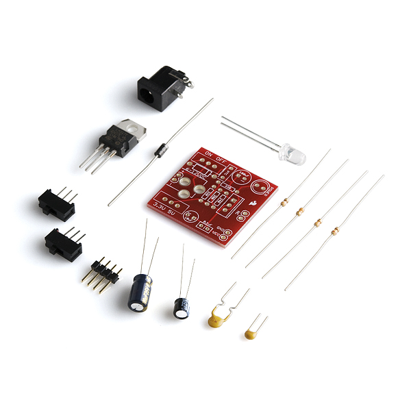
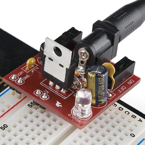
Here is a very simple breadboard power supply kit that takes power from a DC wall wart and outputs a selectable 5V or 3.3V regulated voltage. The .1" headers are mounted on the bottom of the PCB for simple insertion into a breadboard. Pins labeled VCC and GND plug directly into the power lines. The lone pair of pins have no electrical connection but help support the PCB.
There are two pins available within the barrel jack footprint. Any stripped +/- DC supply can be connected instead of the barrel connector. Board has both an On/Off switch and a voltage select switch (3.3V/5V).
Comes as a bag of parts kit and is easily assembled if you can follow the silkscreen indicators and have beginning experience with a soldering iron. You will need to read the resistor bands or use a multimeter to determine the resistor sizes.
- DC Barrel Connector (2.1mm center positive)
- TO-220 Voltage Regulator (LM317 1.5A max current)
- 1N4004 Reverse Protection Diode
- 100uF 25V Capacitor
- 10uF 25V Capacitor
- 0.1uF 50V Capacitor
- Red Power LED - High Brightness
- 2 x SPDT Slide Switch
- 4 x 0.1" Header Pins
- 2 x 330 Resistor 1/6W
- 390 Resistor 1/6W
- 240 Resistor 1/6W
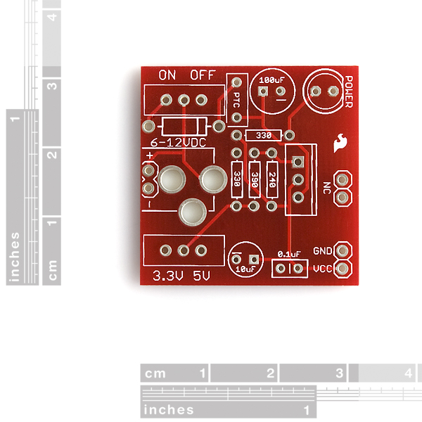
- Bare PCB with Silkscreen Indicators
- PTC resettable fuse
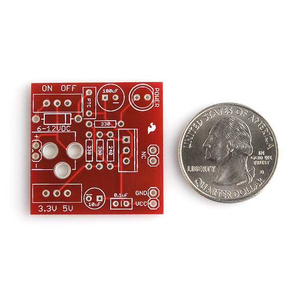
- 1.25x1.25"
SparkFun Breadboard Power Supply 5V/3.3V Product Help and Resources
How to Use a Breadboard
May 14, 2013
Welcome to the wonderful world of breadboards. Here we will learn what a breadboard is and how to use one to build your very first circuit.
Core Skill: Soldering
This skill defines how difficult the soldering is on a particular product. It might be a couple simple solder joints, or require special reflow tools.
Skill Level: Rookie - The number of pins increases, and you will have to determine polarity of components and some of the components might be a bit trickier or close together. You might need solder wick or flux.
See all skill levels
Core Skill: Electrical Prototyping
If it requires power, you need to know how much, what all the pins do, and how to hook it up. You may need to reference datasheets, schematics, and know the ins and outs of electronics.
Skill Level: Rookie - You may be required to know a bit more about the component, such as orientation, or how to hook it up, in addition to power requirements. You will need to understand polarized components.
See all skill levels
Comments
Looking for answers to technical questions?
We welcome your comments and suggestions below. However, if you are looking for solutions to technical questions please see our Technical Assistance page.
Customer Reviews
4.4 out of 5
Based on 18 ratings:
5 of 5 found this helpful:
Convenient breadboard power supply, but limited to 250mA
This is a very convenient unit for powering components on a bread board without burning out the PS on the Arduino. An ON/OFF switch and a 3.3/5V switch make it very versatile. And the power status LED let's you know right away whether the board is live or if it's safe to connect/disconnect parts. However, the product description does not include the max current the board will support. Mention is made of the "TO-220 Voltage Regulator (LM317 1.5A max current)" which led me to believe I was getting a 1.5A power supply. But the board as a PTC (Positive Temperature Coefficient) fuse that, according to the schematic, limits the current to 500mA and, according to the Sparkfun page for the component, COM-08357, limits the current to 250mA. I'm thinking of just shorting out the PTC fuse with either a wire or a replaceable fuse holder with a 1 to 1.5A fuse in it, but I haven't researched this yet. In particular, it is not clear from the description if all the components can handle 1.5A or if it's just the LM317 regulator.
1 of 1 found this helpful:
Works 100%
Works great so far!
1 of 1 found this helpful:
Equal to Tylenol!
Been playing around with a Pickit 3 for a while, always have programming issues. Ran a voltmeter across the powers and discovered Pickit 3 doesn't always supply the best voltages. Bought this little guy, shipping was a bit pricey for being USPS, especially for a kit and coming from Colorado to Nebraska. After assembly and a couple more hours of banging head on table, I was finally able to program my PICs without problems. So proud of myself!
2 of 2 found this helpful:
Like it!
Works as advertised. Easy to assemble. Was missing the 330 Ohm resistors and one switch was faulty so I could only get 5V out of it.
1 of 2 found this helpful:
make one change and add an option
Modify the lone pair of pins that have no connection (NC)to have a direct connection to the DC from the wall wart.
Add another product that has the exact part count except for the circuit board and the switches.
I would then order the first for breadboarding and the second for any projects that I build after that.
Great little kit
Very easy to put together and power your project. Missed being 5 stars by not having the parts labeled in the bag (at least for the educational aspect of it) and if there was a way to tap into both 3.3 and 5v with an extra set of headers before the regulator would make it a solid 5 stars.
That PSU is great!
That PSU has the most stable voltage output I have ever seen. Also easy to build.
Works for me!
I like the fact that it comes un-assembled. I just needed the regulator portion of the circuit, not the input jack or the output pins, or even the switches. I can use those parts on another project. Perfect!
Not sure what I did wrong
I get 3.3 volts no matter where the switch is. Also, when I try to power something the light starts flickering
Sorry to hear you're having trouble! Please contact our technical assistance team and they will be happy to help you with this.
Wish it had a heat sink
Easy enough to assemble, and works fine. But with a 15V supply the regulator gets worryingly hot, even when lightly loaded. I know the LM317 regulator has built-in thermal protection, but I'd feel better (and pay more) if SparkFun had included a simple heat sink.
Also: I wish they had included a takeoff pad for the raw, unregulated input. You can tap it from one of the points underneath the barrel jack, but it's not an ideal solution.
Hello, and thanks for the feedback! If you can, lowering your input voltage will help a lot with the heat you're seeing with 7 to 9 volts being ideal. If you can't lower your input voltage, we do have a heatsink that will fit. Check out our part number PRT-14340 for that. If you have any small bits of scrap aluminum, you might try one of those too.
Basically works, but doesn't fit my breadboard...
For whatever reason, the breadboard I usually use has one more pin of spacing between the rails and the main board area, so I can only put in one of the two "NC" pins. Also, I'd sort of prefer one that could work off of 5V; this one needs 6-12V, but most of my power supplies are 5V. On the other hand, it works fine and does what it's supposed to do. Note the 250mA current limit; the 1.5A current listed for the voltage regulator doesn't matter much with a (resettable) fuse in the way. Pretty straightforward. All the parts have suitable labels on them one way or another, except you have to guess that the PTC is the thing with the weird squiggly legs.
Does what it's supposed to do, but I could imagine an improved design. (I'd probably suggest doing maybe a 4-pin slot for the "NC" pins, and just letting people pick where to put it, maybe?)
Fun starter project
As a newbie to electronics, I figured this would be a good introductory project to cut my teeth on. I've had several cheap breadboard power supplies die on me for various reasons, so I was looking forward to something I could craft myself and could use for future projects.
I'd give 4 and 1/2 stars if I could. The documentation was useful, although I built it out of the recommended order. I started with the center of the board with the three resistors and worked my way outward.
The only issue I encountered was with the LED.
After assembly, I plugged in a wall wart to the DC jack and was disappointed when the power LED did not light up. I tested the wall wart, inspected my soldered connections under magnification, and touched up any that I thought were dodgy, to no effect. I tested a few areas on the board and was happy to see the voltage output was within spec. Testing the LED solder joints showed the correct voltage for the setting on the switch.
I stepped away, and when I came back, I tried the wall wart once again. This time the LED lit up but very faintly. I thought I perhaps installed a resistor in an incorrect position, but after checking my work and verifying that the components were installed correctly, I grabbed an LED out of my parts bin and swapped it out. This time I was greeted with a bright output from the new LED.
Project was a pleasure to assemble, clear labeling in the documentation made part identification a breeze. Aside from a bunk LED, I had no issues completing the build. I look forward to assembling other kits like this in the future.
Sorry about that problematic LED. Glad you enjoyed the product otherwise. If you wanted to fill out a return ticket we can get that replaced if you like: https://www.sparkfun.com/returns
Very handy for powering breadboards
Super easy to assemble and provides either 3.3V or 5V to the power rails on your bread board. You'll lose a bit of breadboard real estate in order to properly support the module, but it's pretty easy to deal with. Breadboards are modular!
Worked perfectly first time
I wanted something to do to brush up on my soldering before attempting to solder all the header pins to my ESP32-S2 Thing Plus, this was good practice and it worked perfectly first time.
Very easy!
A good buy
It was easy to assemble and does what it is designed to do.
Very handy for breadboard projects
more time spent playing with circuits, less time worrying about power conditioning!
Great power supply, easy to assemble
Gee, I haven't soldered a circuit board for over 25 years (I started when I was 3 yrs old, lol...) but this was easy enough. The 1/16W resistors are virtually impossible to decode, so you might want a multi-meter to be sure which are which. I would suggest to not solder the parts in their order though -- go from smallest (the resistors) to the bigger parts. I used little pieces of painter tape (the blue stuff, masking tape would work too) to keep the parts in place on the board while I soldered them. Another tip, do the header pins last -- plug the pins into an actual breadboard in place, put something small as a spacer under the other side of the board to make it level, then tape it down solidly to the breadboard, then solder the pins. I built 2 and both worked presto whizzo.
I bought 3 or 4 of the above "SparkFun Breadboard Power Supply 5V/3.3V" and I soldered 2 of them on the circuit board that comes with it. I was a little disappointed that it did not give me exactly 5V on the open voltage and I thought this might be due to the led.
I also wanted to use this in a low power circuit so the led and the 330Ohm resistor needed to be disconnectable after validating that the module works.
Looking at the schematic trying to figure out how to modify it, I noticed the following: - You have this top line that goes across from left to right that is the +ve Volt line. It reminds me of a clothesline with D1, F1, LM317 on the line. Then you have resistors and capacitors hanging down the +ve line like clothes except if you look at the ground symbols you can think of them as a ground line going from left to right parallel to the +ve line.
Thinking of the circuit that way made the circuit simpler to implement and I opted to use Sparkfun "SparkFun Solder-able Breadboard - Mini" because it has parallel line and you can "hang" the resistors/ capacitors between the lines. I ended up using half the length of "SparkFun Solder-able Breadboard - Mini" and the overall area occupied by the circuitry was smaller than that of the circuit board that comes in the kit. I kept the LED and its resistor but used a 3pin connector with a 2pin sleeve so when left/middle pins of the 3 pins connect the led/resistor is in the circuit but if you connect the middle/right pin using sleave the led/resistor is turned off and I get an open voltage of 5.01. And it supports 3.3V. Oh I also replaced the barrel connector with a smaller connector.
Unfortunately, I don't know how to upload my circuit, it looks really cool.
Hmm, I wonder if sparkfun can sell a kit with a "SparkFun Solder-able Breadboard - Mini" that is half the length? :-)
If I wanted to put this on the other side of the breadboard could I just build it upside down?
I just assembled this, and it isn't working. After inspecting it a bit, it seems like the grounds are not all connected on the PCB. Is this a factory defect, or are they connected somewhere in the middle of the board where I can't see them?
Would something like this be a bad way of powering something like an audio amplifier? I tried and I got a lot of noise (feedback), and I am not sure it was because I was using this to power it. Does anybody know?
This is fantastic. First device I have ever soldered and had it done in about 45 minutes. But honestly, who's idea was that LED? If it were any brighter, I'd be blind.
Actually this is a power supply + lamp.
Sorry! They are called super-bright for a reason. A glob on hot-glue or a brushing of sand paper can knock down the intensity.
You don't have to apologise! An overall great kit, although i didn't buy direct from the site.
I replaced the one in the kit with an opaque red one I had in a bundle of LEDs from radio shack. It's much less intense and I still got to use the 330 ohm resistor in the kit.
Before tonight, I'd only used a soldering iron once - to make a patch cable. I built this kit in about 45 minutes and it worked perfectly the first time, giving 3.29V and 4.97V out with the TOL-00298 wall wart. Talk about a confidence builder! Thanks for the great kit!
AAHH MY EYES! IT BURNS! IT BURNS! Pro tip: Bend the leads on the LED by 90 degrees prior to mounting, so that the axis of the LED is parallel to the circuit board. That's what I would do, if I still had my eyesight. Excellent kit, otherwise. My compliments to whoever was responsible for the silk screen. The silk screen was very informative and greatly aided assembly.
Yea - sorry about that. The super-bright LED, is indeed super. You can opaque the leds with sandpaper, scotch tape, or some hot glue. There is nothing that says 'professional' like a pile of green glowing hot-glue.
Since this kit isn't pre-assembled, could one just sub in a different(weaker) LED in it's place?
Yes. Alternatively, you can replace the 330 Ohm resistor that leads up to the LED (have a peek at the board) with a higher value one to make the included LED shine less bright.
I love this breadboard power supply. My only complaint is the switch (S2) to select 3.3V or 5.0V. More than once when I intended to turn the supply off via S1, I instead switched S2 causing the output to change from 3.3V to 5.0V. Not good when your circuitry is not 5V tolerant! I've since removed S2 and replaced it with a 3-pin 0.1" header. I use a shorting jumper to select 3.3V or 5.0V (actually, with no jumper, the output is 5.0V).
I recommend using a 9V power supply with this kit. You will only get 3V (on the 5V setting) if you use a 5V power supply.
Alternatively, you can use a different linear regulator with a lower dropout than the ancient LM317. Most of the true LDOs have more than three terminals: Input, adjust, ground, enable, and output. For instance, LT's LT1963 or LT1764 (higher amperage) have a 0.3V dropout at their maximum output current: You can get over 4.5V with a 5V supply, instead of the 2V dropout you get with an LM317.
This kit was indeed a very nice one to put together.
Thanks to the wonderfull silkscreen, the kit could be soldered together in no time and without having to look at the schematic or anything else.
Congratulations on another fine product.
What's funny is that I designed myself a nice little switchable power supply in Eagle right after reading the tutorial and was going to get some boards printed. When I came to order some parts, I found this!
Excellent little kit, really easy to assemble, and a great regulated power supply for projects.
You can also put a trim pot in place of the fixed resistors and voltage switch for a variable-voltage power supply, depending on your wall wart's output voltage.
I haven't had too much experience with trim pots, but I would think that they might wear out quickly if used for changing the power output, especially if you are working with many different systems. Maybe a regular linear pot instead?
Trim pots are fine and don't wear out any more than any other kind of pot.
Also I don't think linear pots are the "regular" ones. Aside from audio mixing equipment I almost exclusively see rotary pots.
linear taper are logarithmic not linear. reason ... usually thing in audio feedback amps are by dB,
I'm guessing PresidentOfAwesomeness is referring to "linear taper".
this is a very good product. I built it in about 25 minutes. and it works very well.
This item worked out great for my usage. It went together in about twenty minutes and worked perfectly. For this price I don?t think you can beat this item.
does anybody know the maximum voltage input the jack can take on this supply?
I actually didn't find the bright LED to be a problem, it wasn't uncomfortable to my eyes or anything. The kit worked like a charm, only observation I can make is that it won't work with a wall wart with an output of less than 9V, it won't even turn on the LED, if you have a >9V wall wart, you're good to go.
Important note: this is a 250 mA power supply! As others have mentioned, the PTC fuse limits the output current to no more than 250 mA. It would be great if you could change the item description - calling it "1.5A max current" as shown above is misleading and confusing.
This is great. Did not take that long to solder. Does this work with 5V DC power supply? I tested it and it did not. I am assuming it is only compatible with 9V DC.
A simple and reliable kit. The only trouble I had was that I tested it on a breadboard with two separate regions, served by two different power rails. So it looked like it wasn't working until I put my jumpers into the correct holes. So, pro tip: study the anatomy of your breadboard before testing.l
I have only used this for less than 2 hours 10 minutes at a time for my Digital Electronics class and I have a problem.
The larger of the capacitors burned me when I picked it up after the LED dimmed rather quickly and now it won't work.
I had one of the Seniors in my major check it out, he said, "It is soldered correctly and there aren't any leads touching
Hi, I recently ordered this kit and I soldered all the components following carefully the steps. When I test it with a 12v 1,5A power supply, I get 11v out of the kit. When I test it with a 9v, 800mA power supply, I get 8v out of the kit.The voltage coming out from the kit doesnt change if I switch 3,3v/5v.
Obviously, the voltage is not lowered by the kit, assuming that the LM317 doesn't do its job?
As a beginner, I have no idea why it doesnt... =(
Thanks for your help :))
What's a reasonable load for this power supply?
Just to throw out a number, would 10 watts be okay? With a heatsink?
Excellent kit, three minor suggestions. I concur with replacing the LED with a standard one. Super-brights are great for certain applications, but not this one. That said, I just swapped it with a cheaper one I had on hand. Second suggestion, place the "dummy" pins further out from the power pins. #1, wider == more stability. #2, I have a breadboard that has more space between the power rail and the main board, unless I clip the inside pin off, I cannot use this power supply on that board easily. I would move it at least one position, preferably two. Third suggestion, do away with the switch for 3.3v/5v, replace it with header pins and a jumper. As has been noted previously, much safer that way.
So this is embarrassing, I soldered it together (first soldering) but the output is around 8v it fluctuates by about .1v when I switch from 5v to 3.5v. I'm using a 9v 1.5A switching mode wall wart for what it's worth. Anyone know what could be wrong with it or how I can fix it?
In general, I would check for shorts or bad solder joints. There's surprisingly many points where things can go wrong, even with such a small circuit :)
That said, you say you've got a 9V power supply (measured?) and are measuring around 8V on the output, so at least it seems unlikely that you have a short circuit from your power supply to the output directly, which would be difficult to do with the board laid out as it is anyway. There's basically a few sections to the circuit (ignoring the regulator itself), input, feedback and output.
If you look at the schematic, you'll see that your power supply input goes through a diode (with a small voltage drop), and a PTC resettable fuse (with a negligible drop unless it's heating up) before it gets to the regulator. You'll also see a small test point named 'RAW' there. There's no associated pad on the board, but you should be able to measure at the inside pin of the PTC (right next to the on/off switch). If this voltage is the same as the voltage you're getting at the output, it seems likely that you have a short between the input and output pins on the board, most likely at the regulator itself.
If you see a higher value there, then the regulator is at least doing something, but not what it's supposed to. One possibility there is that it doesn't have the appropriate feedback on the adjust pin - this is the pin that leads up to the 3 resistors in the middle of the board. Check the solder joints at those resistors, perhaps one of them didn't quite get soldered down right making the regulator try to output a very high voltage, getting limited by your power supply, the voltage drop in the input section, and its own drop. Normally the combination of the 390 Ohm / 240 Ohm, or (390 Ohm + 330 Ohm) / 240 Ohm, are what set the voltage (nearly 3.3V, and 5V respectively).
Lastly there's the output section, but there's nothing particularly exciting going on there. I'd be cautious leaving it powered in its current state for long, though, as that LED can't be happy about the excess of power it's getting :)
The above are just guesses, so good luck, and please do follow up if you find the culprit :)
That was it! I took my soldering iron to the middle prong of the voltage regulator which had a bit of solder pretty close to the prong next to it and got it out with my solder sucker. Hooked it up and it read 5 even :) Thanks for taking the time to help, I didn't know where to start.
Just finished assembling. It's rather straight forward and easy. I didn't use the voltage select switch, I used some header pins and a "shorting jumper", as I plan on leaving this in a project. It would be nice if you had just 5V or just 3.3V versions. Not that it's difficult to make a simple 5V regulator, it's just nice to have a good looking PCB. Perhaps you could make "Breakout boards" for the 5V regulator and 3.3V regulator? Most of us have the regulators and caps on hand.
Using this kit for parts on my perf board, and had a question about the schematic:
Is one side of the voltage select switch disconnected from everything?
I used two of these guys in a Halloween project. However, the Raspberry Pi with a wifi nub will draw too much current. I just shorted across the PTC so that the Pi and the servos could get the juice they craved.
http://www.youtube.com/watch?v=7T7kwsECvPY
The LED is too bright?? Be glad they didn't put a green rebel LED on it. No photo or description can cover what one of those little things put out.
I've never been too big into kits, like to put together stuff myself. But I threw this in with one of my orders and I'm loving it. Just slap it together, plug in a spare wall wart lying around and makes getting power so much easier.
I have a question about an idea for a project that I have. I want to make a solar powered cell phone charger using a panel I have laying around. The sticker on the panel says Pmax:8W and Vmax17V but I tested it and it puts out about 20V Max when in direct sun light. Can I hook that up to this power supply and get a steady 5V to charge a phone? And is this safe for a phone? How do I know how much amperage this will put out? Because I know nowadays phone chargers are rated at about 1amp more or less. I wouldnt want to make this anything over 2amps. Hopefully someone can answer. Thanks in advance!
I've just soldered up my second of these. The first has been in constant use for a few months with no problems and the new one is for a new project. Re: the LED. I just left them out. Is that going to be a problem? Both are powering Arduino Pro Minis. Of course I now don't know if the PSU is powered up, but the Arduino has its own power LED so for my purposes that's enough information. As I said the first PSU is still working with no problems.
This is a great kit and easy as anything to put together. Just be methodical and don't rush.
What's the minimum input for this board? I'm using 5V DC and the output is always around 3V regardless of 3V/5V switch. Any ideas?
on the kit I got, 6-12 V was printed on the board for an input voltage
I'm not seeing some pieces information that would be really useful to have before buying:
25 minutes of soldering, perfect output ... 3.298V and 4.997V. Viva la SparkFun!
Could i add wires (or a header, to the 3.3v\5v instead of the selector switch to get both 5V and 3.3V?
Nope, nice idea, but the circuit isn't constructed that way.
The switch effectively sends a signal to the regulator (via a changing resistance) to tell it what output voltage to produce. Putting a header on the switch would not give you access to two outputs.
Hmm. I don't see a amperage rating for the output anywhere in the description or comments. Anyone?
Thanks,
Michael
LM317 - 1.5A max current
I know this is old but: The PTC is set for 250mA. Anything over that and it will stop working (unless you bypass the PTC)
The "Quickstart Guide" link is borked. Looks like it should be <a href="http://www.sparkfun.com/tutorials/103">http://www.sparkfun.com/tutorials/103</a>
6v input and I cant even get 2 watts out at 3.3v =/ My poor bullet Radio goes into brown out once it finished booting up. Had to tap into the computers 3.3v to get enough power... Bullet radio with its own PSU pulls 2 watts from the wall with a Kill-A-Watt. I really dont think I'm getting my 1.5A worth =/
Hi - need help from you experts please - I just put this power supply together. I get 3.27V when the switch is on 3.3V and nothing when I switch it over to 5V. I've rechecked the solder points on the V switch but other than that what else would it be?
are you using enough voltage input? you need to feed it at least 6v to regulate down.
I'm going to be supplying 24v to my drive system via two 12v marine batteries in a series. Will this unit be able to step down the voltage for my Arduino, or is there another that I should look at? Thanks.
The board is based around an LM317 voltage regulator. The datasheet says the max Vin - Vout = 37V, so it should theoretically work on 24V. However, linear regulators work by converting the voltage difference into heat, so the bigger the Vi-Vo, the hotter it will get, and without additional heatsinking it may decide to shut itself down. Give it a shot, and if it gets too hot, you might stick one of these on it. (You could also drive it off the lower battery by itself for 12V in).
Thanks Mike, I'll give it a try. :)
I have this kit and it does work however that LM317 gets hot as all heck, even under minimal load. I grabbed a cheap heatsink to place on the LM317 to help it ditch the heat without dying.
As for the LED, save your eyes, do NOT install the red water clear LED. Grab a diffused LED from your parts drawer (you know you have some) and use it instead.
Aside from the heat issue on the reg and the LED that I was quick enough to avoid, this PSU now hangs off the end of my breadboard and does a very good job.
What's the input voltage? If it's more than, say, 12 volts, it'll get pretty darn hot. However, you're in luck because the LM317 has built in thermal overload protection, so that if the regulator gets hot as a result of using the wrong AC adapter, or a downstream component failing shorted, it will temporarily shut down (technically it drops the voltage-it doesn't shut off completely-but it generally has the same effect)
Run the numbers based on your input voltage (Vin - Vout) * Amps = Watts. In a nutshell, the bigger the difference between Vin and Vout, the hotter the regulator will get under the same current draw. At some point this will be too much, but as mentioned above, the regulator has thermal overload protection (Don't ask me how they put that in the TO220 case) so it's not going to ruin it, at least not right away. However, a prolonged or repeated overheat condition could still shorten the life of the regulator-hence the need for a heat sink.
Echoing the above comments, got it today, 45 mins assembly (only because I wasn't 100% on a couple of things), powered up and boom goes the dynamite, a ps for my breadboard! I apparently have either bad vision or just don't mind the bright LED, so I'm leaving it. Great kit Spark, very much enjoyed it!
If you're new to all of this, couple of hints if your confused. The silver band on the reverse protection diode (the black barrel with the two wires coming out) goes over the line divide on the silkscreen. The pic above is pretty accurate for placement. If you have an Android phone, I highly recommend ElectroDroid. It's free (But I encourage you to donate, it's not much and the app is awesome) and you can plug the colors of your resistors in and it gives you the value.
I received my board, soldered everything in about 30 minutes. Great little kit, however I had noticed after I soldered everything together that I had accidentally soldered the 390 ohm resistor where the 330 ohm should be and the 330 is at the 390 location on the board. Would this be a problem? or do I need to desolder these components?
I suppose you switched the 330 and 390 resistors of the LM317, not the 330 current-limiting resistor of the LED.
Desolder them, or you'll get only 3V at the 3.3V setting. Bear in mind the resistors around the LM317 set up the ouput voltage. The output voltage selector in 3.3v shorts to ground after the 390ohm resistor. There you have 330 ohm, which if you calculate with an online LM317 calculator is barely 3volts. If left unshorted (5v) both resistor values are summed up, so it doesn't matter if it's 330+390 or 390+330, but it does make a difference if shorted.
If you switched the LED resistor and the 390 resistor, ALL output voltages will be messed up (barely 3v and 4.7v)
When will this be back in stock?
While it is not hard to wire up a regulator chip on a bread board, it's awfully nice to have this little unit handy. It took me about 15 minutes to solder up...not much longer than it takes to breadboard up a regulator circuit. With this in my parts box, I can plug it in and be off to work on the rest of my new circuits in a few seconds without taking the time to make a power supply as the first step in every new project.
Thanks to the commentators here, I did swap out the supplied ultra-brite red LED for a diffuse green one.
I just put this power supply kit together. It works great. I plugged it in to my breadboard and fired up three LEDs. It was fairly easy to put together especially for a beginner like me. The only thing I had any kind of difficulty with was the DC Barrel Connector with those big holes in the board. There isn't much for the solder to grab hold of so I ended up bending them over as much as I could. I'm thinking now that I could have soldered in a couple of short header pins underneath the DC Barrel Connector so it can sit a little more snug on the breadboard.
Does anyone have any suggestions for installing the DC Barrel Connector better? I would be interested in hearing from others how they installed this piece.
Anyway fun kit. The silkscreen on the board made it easy to install the components without any other written instructions.
I put a small spot of super glue on the bottom of the plastic enclosure then positioned the tabs going through the hole in such a way that all three of them were to one side of their respective holes. Then I just flooded the tab that was closest to the edge of the hole.
New to electronics with lots still to learn. Could I swap out the LED that comes with the kit with another LED? I have some 5mm red LEDs.
Is there a way to make the voltage on this adjustable? I want to make a step down cable to run my 7.2v DSLR from a 14.4v battery pack.
You could solder different resistors in to get a different voltage.
This board is specifically designed for 5 or 3.3v output. For your DSLR, you will want something like this:
http://www.sparkfun.com/products/527
But keep in mind you will lose power doing it this way. No regulator circuit is going to be 100% efficient.
I know it's a minor detail, but the schematic should be updated to include the PIC fuse.
I like these little guys so much I got a couple. They're actually capable of delivering at least 2-3 times the current that the PTC limits them to. I have a project that needs ~300mA and the PTC was kicking in, so I soldered a short jumper across it. I also added a heat sink to the voltage regulator as it was getting pretty warm on its own at that point (I'm using these power supplies along with the 9V 650mA regulated wall warts sold here. Like those, too.)
The PTC is a great feature though, especially for beginners who are more likely to wire something wrong. Now that I've said that, watch me go fry something ;-/
Gotta love the pilot light too. I never forget where I put my project any more.
Just out of curiosity... why is the vcc pin on the outside of the PCB and the gnd on the inside? In the picture shown, the power is reversed from what is standard on bread boards. Not that this is a big deal, just seems that it would be easy to forget and screw up your pin-out down the line. Otherwise great product!
Because they plugged it in at the bottom of the board for the picture! Plug it in at the top and it will line up correctly. I.e., when you just rotate it 180 degrees it lines up...
Turn your breadboard around ;)
With row 1 on the left, gnd is on the top; with row 1 on the right, +V is on the top.
Took me like 2 hours to put together. Burned myself multiple times. Didn't work in the end, had to double check all my soldering connections. Now possess utter terror of soldering irons and wall sockets, but got it working...
Please lose the bright LED!
And you should make the connectors the same layout as the USB version. Vcc-GND and the diagonal thing. This thing doesn't stay fit. And i blew up my wwvb nist receiver...
Resisters I got - via MM test:
(1) 330
(2) 282
(1) 215
By my read, I need a 390, another 330, and a 240.
What the dealeo?
Also, why not include a top level picture? The side pics mask too much. tia
@c47334, @Maragnus: thanks for the heads up about the blinding LED - I replaced it with something calmer.
@Nate & Co: I notice the schematic is missing the PTC fuse.
Actually, does it even need the fuse? The LM317 regulator spec sheet claims that it's "short circuit protected".
It'd be nice to publish a spec sheet for the device. In my experience with a 9v & 12v warts, the fuse is only good to about 4-500mA on the 5v setting, and the LM317 gets ouch! warm when the current gets up that high.
I'd recommended it for projects drawing 300ma or less unless you short the fuse and consider a heat sink for the regulator.
Not only is the PTC missing, but the diode and switch are also the wrong way around. Nothing major, but it's out of date.
Keep in mind that you could just change the LEDs resistor to make it dimmer.
I have a different breadboard so I'm personally going to use a female header facing upwards so I can just connect it with wires.
Something strange happened. Ive completed soldering my breadboard powersupply. After a few seconds of blindness (caused by LED) ive decided to use with my sharp proximity sensor. I connected it properly and it was like sharp doesnt supplied porperly because nothing was on the serial monitor. I measured sharp, power supply terminals and it was fine (5.06V) but it was not working nothing on my arduinos serial monitor. I tried to use arduino's main board supply, connected it to sharp and it was working and measured again it was 4.96V on the sharps terminals. Couldn't figured out this one... Both of them (sharp and breadboard psu, breadboard) was working fine but not working together.
The layout shown in the picture contains errors.
The pin headers are supposed to be oriented with the short lead through the board and the plastic on the underside. Two headers should go through the VCC & GND holes, and the second two should go through the NC holes (take care when cutting them apart).
The point of this is that you can insert it into a breadboard. The VCC & GND pins will connect to the breadboard's power bus, and the NC pins will provide mechanical stabilization in the closest two holes adjacent to the power bus.
The assembled board shown in the picture is otherwise correct (except perhaps the resistors - I'm colorblind). Everything is nicely labeled on the board as well. Pay attention to the picture and the on-board documentation, make sure you orient your caps and diodes and LM317 correctly, and this will make a great first/early soldering project which coincidentally gives you something you need for prototyping work.
I built mine today. Took maybe... 30 minutes?
Only two confusing bits... in the picture of the completed project... the two pins (VCC and GND) show the pins sticking way up. They should be going down.
The other set of pins go under the barrel jack (at least, that's where I put them). They help support the board.
I tested it out... using my DMM and running in "battery" mode... I got 3.2 and 5.0 voltage. When I switched it to DC voltage... I get 3.3 and 5.01 - So be careful what settings you use on your DMM when testing it too.
First board I ever assembled. sure enuff 4.94 and 3.29V, first try. Took me a while to figure out the resistors since they are tiny, but SF ROCKS!!!!. Now on to the PICAXE 18X High Power Project Board and beyond!!!! Too cool. and the LED is super bright, just like they said. I'm jazzed!!!!
I have a problem with mine as it seems to only deliver 3.6 (V) with 5(V) selected and 2.7 (V) with 3.3 (V) selected.
Also note that I am using a TOL-00298 9VDC 650mA wall adapter and I am still not getting the desired output??
Any suggestions??
Please contact tech support at techsupport@sparkfun.com. Thank you.
I used right-angle headers so I can plug this vertically into a breadboard.
Would this be able to handle using a 3s or 4s lipo as the input voltage? I would be stoked if it could handle up to a 6s lipo. If this wont work can anyone point me to something that would please. Thanks for any help
Great kit for even an uber n00b! 3.34V and 5.08V output options using your 9V DC adapter. First time soldering, but I managed to keep the contacts separate even on some of the close ones. Definitely use a pen tip solder iron if you have one. Mine is an older beveled tip like a fat flathead screwdriver... not very easy for the small wire contacts. For the capacitors... anode (long pin if it has one) goes to square marking on PCB. Also, the negative hole is marked with a minus "-" sign (location for shorter of the two wires). First PCB experience, so I had to look this up.
Power Supply is very handy!
Product Suggestion: to complement this breadboard power supply. I would love to have just a small serial 1x8 LCD or as big as 2x16 if not too heavy I'm good with a couple of legs to touch my desk in order to get 2x16, setup like this power supply with the pins lined up for a Breadboard. So instead of using a single LED to debug programs with, I could use that same "Debug" pin to get real information from my programs.
will this run using a 9v LiPo rechargable battery? I was planning on running something had between 2.0-3.0 ohms resistance. Very much an electronics noob....but this might be perfect for an idea I got brewing.
Yes, that should work fine. Powering it with 5v, i can get an ok 3v output, but only about 3.5 (when selecting 5v). So, 9v should be a good input for either voltage.
The kits we've received don't have all the included parts, but they do have the PTC in them, the 10uF capacitor is missing but seems to have an axial looking part instead, can you help?
I included one of these cool little power supplies in my Free Day order that never got through. I decided I wanted it enough to pay for it myself. I found the kit went together super easy and the output voltages were in tolerance. The only thing I don't like is that blinding LED. Super bright it is! If I knew it was going to be so bright I would have subsituted a surplus LED and saved the Super bright one for a flasher to use while riding my bike at night.
Will this power a WIImote.. which runs off 2xAA batts.. 1.5v or 1.2v recharges? I know sometimes a 1.5v bat will put off more, so I'm guessing that the WIImote can handle 3.3v fine.
it seems similar to this design http://miskatonic-tech.blogspot.com/2009/12/usb-powered-nintendo-wii-remote-wiimote.html
I just finished assembling and soldering mine tonight. Wasn't difficult at all and good practice for me. It was such a great relief when I saw that bright red LED light up when I plugged the 9 volt 350mA wall wart.
I then checked the voltages and got 3.34 volts on the 3.3v and 5.12 volts on the 5v. It's all good. Thanks SparkFun for such a good kit. :)
Just received mine today, took 15 minutes to assemble. Silk screen was really helpful and as a newbie to soldering it was a "cake-walk." Couldn't have been more pleased, with the finished product. Multimeter reads 5.05V and 3.28V well within the tolerances of this circuit.
Silly question, but what's the maximum current draw I can put through this on a sustained level before risking a burn out?
The PTC fuse is rated at 250 mA at least...
I built two of these power supplies this afternoon; the boards are nice quality, and the kits went together nicely.
Quick question: Looking at the schematic, it appears there are three smoothing caps: 100uF, 10uF, and 0.1uF. Why is the 100uF cap placed on the Vin side of the regulator, but the other two are on the Vout side?
Warning: Take this with a grain of salt
The 100uf cap is to smooth out the bigger ripples before the regulator. Then, the regulator does its best to smooth the electricity flow even more. However, it doesn't do a good job a the higher frequencies of ripple so the smart engineer places to small caps a the Vout side to smooth it out even more. Thats my edgy-cated guess :D.
First kit ordered, and first time I used a soldering iron .. No problems, kit went together easy, and worked the first time!.
Thanks to the comments on here i replaced the super bright led with different one that doesn't blind!.
Good job guys .. this is way fun!
What's the best way to get the pins straight on the output? I just warmed up the joint and used needlenose pliers to get them straight enough to insert, but there's got to be a better way.
the best way to solder the headers in is to put them in the breadboard first... although I dont like how this model hangs off the edge of the breadboard... I used a piece of foam to give it support
Used this part in this:
http://www.flickr.com/photos/sparkfun/3926747868/
I'll be putting together my breadboard power supply kit tonight.
I get bypassing the PTC if I want to be able to supply more current (and I've got a TO-220 heat sink kit in the parts box, I'll see if it fits), and doing something to avoid LED eye burnout :-)
The last time I remember looking at the LMx17 datasheet, I thought a 10uF bypass from the adjust pin to ground improved ripple rejection significantly. I don't see anything like that on the schematic. Is that an old technique that isn't necessary with modern LM317s, not done to keep cost and/or size down, or for some other reason?
Whose idea was it to put the input header holes off of the 0.100 grid?! My project has this board as a piggyback board on a 0.100 protoboard. Must have been that Arduino gremlin :-(
I also wish that it was made more clear that the max input was 12V. I now need to scrounge a 50V cap for a 24V input.
This was one of the first kits I ever ordered from Sparkfun. I was intimidated by the lack of instructions at first, but the silkscreen labels are EXCELLENT. It worked the first time I powered it on, with 4.93 V and 3.24 V output. My only nitpick is that some of the resistor holes are a bit close together, so you have to be a bit careful not to over-do the solder.
One tip: To make the pins a bit more sturdy, I put a tiny bit of superglue on the underside of the board where they join the board.
What should be the max input voltage from the wall wart?
The max input voltage of the Lm317 is 40 volts but the schematic says it's max 10 volts. Does it get to hot when used with an 15 volt supply or can it be done?
It depends on the current draw of your circuit. With a 15V input, and a 3.3V output, anything above 50mA is going to get warm. I'd recommend keeping the input to 7-12V if you need more than ~500mA.
im trying to use this to power a tamiya gear box and to do so i need to get rid of the PTC. how can i safely remove it from the equation?
Soldering a piece of wire across the legs of the PTC is not safe. It exposes your circuit to whatever current your power supply can generate. If this is, for example, an automotive lead-acid battery, you could potentially cause a fire.
If you need a lower series resistance for some reason, you may be able to use a true fuse. Note that this means that you'll lose the resetting function of the PTC, and have to solder in a new fuse every time it blows. Alternatively, you could substitute a higher-current PTC.
You can get through-hole fuses for about 50 cents each.
I would just solder a piece of wire across the legs of the PTC - effectively shorting over it.
In the picture you can see 4 capacitors, but the parts list contains only 3.
Is the last one nessesary ?
The free spot on the board reads "PTC"
This was my first circuit board...ever. It took less than an hour after I figured out the biggest issue: My kit INCLUDED the PTC (or Thermister - see http://www.sparkfun.com/commerce/tutorial_info.php?tutorials_id=57) but NOT the .1 uF Capacitor. As of 11-11-08, the PTC is not in the wiring diagram (the USB version does show this). Anyhow, it worked first time.
Great kit: inexpensive, easy to build, and lets you reuse a wall-wart that you might have laying around (I'm using one from a dead Netgear switch). The ability to select 3.3 or 5 volt output is a big plus, and I like the way it plugs directly into the breadboard.
I like the bread board power supply for getting projects up quick. It would be great if you also made a second power supply kit that had 3.3V and 5V outputs for imbedded use. One example is running a serial backpack LCD at 5V and Xbee at 3V. Logic and voltage complicate an easy project, fortunately your serial shifter makes quick work of the logic.
Does anyone know the value of the capacitor in the PTC slot? It doesn't show up in the schematics.
~thanks!
As Nate pointed out, it's not a capacitor. It's in series, so a cap would block the DC current, and this circuit wouldn't do a thing.
In the schematic, it shows up as a fuse.
Instead of using a fuse, though, SFE used a PTC, or Positive Temperature Coefficient resistor. Under normal operating conditions, it functions as a 2 ohm resistor. However, once you start to pass a lot of current (because your circuit has a short somewhere), it heats up (P = I^2 * R). The PTC part's Temperature Coefficient is positive, so as it heats up, the resistance also increases: R = (Positive #) * Temperature. As the resistance increases, power dissipation remains high, so the resistance continues to increase. Eventually, the resistance is very high, so the current is very low. Your circuit is now off.
Once you remove the short, the PTC cools down, the resistance goes back to an insignificant 2 ohms, and everything starts working again.
The PTC is sold over here: http://www.sparkfun.com/commerce/product_info.php?products_id=8357