- Home
- Product Categories
- 7-Segment
- 7-Segment Display - 20mm (Yellow)

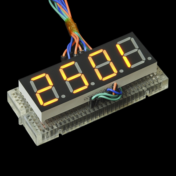
7-Segment Display - 20mm (Yellow)
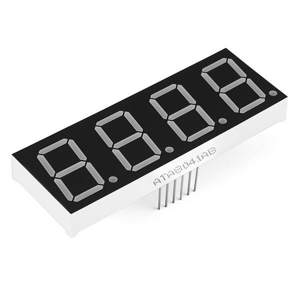
For a long time we've had small 7-segment displays and *huge *7-segment displays, but now we finally have something in between. These 20mm 4-digit 7-segment displays are big enough to see from a distance but not so big that you'd have trouble finding an enclosure for them.
These common-cathode displays feature 4 x 7-segment digits and one decimal point per digit. The LEDs have a forward voltage of 1.9VDC and a max forward current of 20mA.
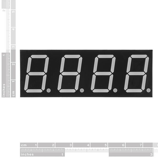
- 71.6 x 25.7mm
7-Segment Display - 20mm (Yellow) Product Help and Resources
Using the Serial 7-Segment Display
August 13, 2013
How to quickly and easily set up the Serial 7-Segment Display and the Serial 7-Segment Display Shield.
Using OpenSegment
April 1, 2013
How to hook up and use the OpenSegment display shield. The OpenSegment is the big brother to the Serial 7-Segment Display. They run on the same firmware, however the OpenSegment is about twice as big.
Core Skill: Electrical Prototyping
If it requires power, you need to know how much, what all the pins do, and how to hook it up. You may need to reference datasheets, schematics, and know the ins and outs of electronics.
Skill Level: Competent - You will be required to reference a datasheet or schematic to know how to use a component. Your knowledge of a datasheet will only require basic features like power requirements, pinouts, or communications type. Also, you may need a power supply that?s greater than 12V or more than 1A worth of current.
See all skill levels
Comments
Looking for answers to technical questions?
We welcome your comments and suggestions below. However, if you are looking for solutions to technical questions please see our Technical Assistance page.
Customer Reviews
No reviews yet.
Seems like no one knows how to use these LOL AWSUM. What a waste of money.
It's a 4-digit 7 segment display... there's really not much to figure out beyond that. If you're using Arduino, there's a 7 segment display library that will drive it directly (you'll just have to check whether the pinout is the same). There's also dedicated 7-segment drivers that use up fewer pins of your uC but obviously add more floorspace. SFE has one for 8 digits, but 4-digit and single digit are easily found as well, or you could use a shift register, etc.
Is there any problem in particular that you're running into?
Thank you for taking the time to reply. That seven segment library will come in handy. My frustration is almost certainly born out of ignorance, though it has been exacerbated by the lack of any "next-step" information in the product description that so regularly accompanies SparkFun product pages. I'm aware of the pin count burden, so I have a couple of shift registers as well as one of those 7-segment drivers. I'm in the process of learning (I'm a software engineer by trade), so I'm reluctant to make assumptions with respect to the pinout and the datasheet is a bit cryptic. Could it be that it contains all the information I need and I am simply not interpreting it correctly? Should I just start applying 5v to various pins and see if I can't figure out the pinout myself? Thanks again!
I do agree that datasheets can be cryptic at times, so let me try and clarify this one a bit because all the information you need does appear to be in there, specifically in sections 3 and 4.
In section 3 you'll find a mechanical outline that also indicates the location of pin 1. With the display facing up, and the decimal points at the bottom, pin 1 is on the bottom-left. The crossmark in that drawing is way off, but let's look past that and just go with 'bottom left'. There's two rows of pins, one at the bottom and one at the top. Pin counting is generally done in a counter-clockwise fashion. So if the pin on the bottom row on the far left is pin 1, then the pin to the right of it is pin 2, the one to the right of that is pin 3 and so on until you get to pin 6. Then you skip up to the top row, all the way to the right, that's pin 7, and then the pin to the left of that is pin 8, etc. until pin 12.
If you look very, very closely at the bottom of this component, pins 1 and 12 should actually be marked out - but it's pretty tiny and under a layer of some murky plastic so that may be hard to spot :)
Then there's the (in this case) yellow drawing of the digits with labels DIG1 through DIG4 - the digits, D1 through D4 - the decimal points, and on DIG4 there's some extra labels, A through G - the segments. Those are basically for reference. The segment labels A though G also apply to DIG1 through DIG3.
Then there's the actual schematic of how this component is internally wired up. You can probably tell there's 4 distinct sections to it for each digit and also labeled as such. Let's focus on just the left-most one for now.
At the top of that one you see a label "12" with below it "COM". That tells us that the pin number being indicated is pin 12 (the top-left one!), and that's the common pin. Even without the "COM" that should be pretty easy to see as it is connected to every single LED's cathode in that group.
Then at the bottom you see pins 11, 7, 4, 2, 1, 10, 5 and 3, which are hooked up to the LEDs labeled A through G and DP respectively. Those A through G labels are the same labels used for the segments in the yellow drawing. If we take pin 11 (right next to pin 12), it tells us that's hooked up to segment A, and the yellow drawing tells us that's the top segment of the 7-segment digit. If we take the one next to it, pin 7, that's hooked up to segment B which according to the yellow drawing is the top-right segment of the 7-segment digit.
We can go through all of those until we get to the one labeled DP. There's no 'DP' in the yellow drawing, but it's referring to the decimal point. Since we're looking at DIG1, DP in this case is actually referring to D1.
Now you could take the continuity tester of your multimeter (if you have one - if you don't, please get one!), or your 5V power AND a 180 Ohm or greater resistor in series with that power to test these segments. The reason you'd want a 180 Ohm or greater resistor is because these LEDs have a 1.9V forward voltage drop (see description), and applying 5V will quickly make the LEDs burn out. The 180 Ohm resistor drops the excess voltage and keeps current down to well below the 20mA maximum (again, see description - the datasheet mentions 35mA, but I wouldn't generally risk it for continuous power.)
Now let's say you're hooking this up on a breadboard and want to make the letter H. If you look at the yellow drawing, you'll see that you'd need segments F, B, G, E and C. If you then look at the circuit diagram, you can trace those segments back to pins 10, 7, 5, 1 and 4. So all you'd have to do is connect the positive bit of your power supply (remember to use the resistor! 1 resistor per segment would be even better.) to those 5 pins, and the negative to the common pin, pin 12.
Now let's say you wanted to display the letter H on the second digit instead. If you look at the circuit diagram closely, you'll notice that pin 11 doesn't just go to segment A on the first digit, but also to segment A on the second, third and fourth digits. The same applies to the other segment pins. The only one that actually changes, is the common pin - instead of connecting the negative power supply to pin 12, you'd connect it to pin 9 instead. If you try this on your breadboard, you should notice that the first digit goes out, and the second one displays the 'H'.
The same thing applies to the third and fourth digits - the segment pins remain the same, only the common pin changes.
This is also how most of these multi-digit displays are driven by a microcontroller. Rather than applying power to each digit simultaneously, they just cycle through the 4, powering each digit one at a time by changing which common pin gets to be connected to the power, and changing the segment pins' states at the same time in order to display, say, the time, or some rudimentary text.
Now that may still sound a bit convoluted; for our brain it would certainly be a lot easier if each LED were simply 2 pins on the component. Of course the component would have 64 pins as a result, wasting a lot of space on a PCB. But a microcontroller doesn't much care that it sounds convoluted, and a microcontroller with a 7-segment library where all you have to do is tell it which pin is what and from thereon just use the library to write out the desired numbers, means a lot less headache for us :)
If there's still something unclear, feel free to ask! If not, have fun - and don't be afraid to experiment (I've had to on mystery dot matrix displays without a datasheet at all before - talk about infuriating, but at least I'd know 100% for sure which pin was what). Just keep in mind that you don't want to apply 5V straight to this :)
Thanks for your lengthy reply - it's proven invaluable!
You might clarify in the descriptions of these (and blue and other colors) that 1" is the package height - the illuminated character height is 0.8".
These are yellow-orange, close to what HTML "gold" looks like. It's actually a very pleasing color.
WHY. ALWAYS. Common anode.
Why not? :) You can find drivers for both common anode and common cathode, and e.g. the Arduino platforms will happily (well.. 'happily') source OR sink current on their I/O pins.
I agree that it would be nice to offer both - and also offer a common anode equivalent of the 8-digit driver SFE carries.