- Home
- Product Categories
- 7-Segment
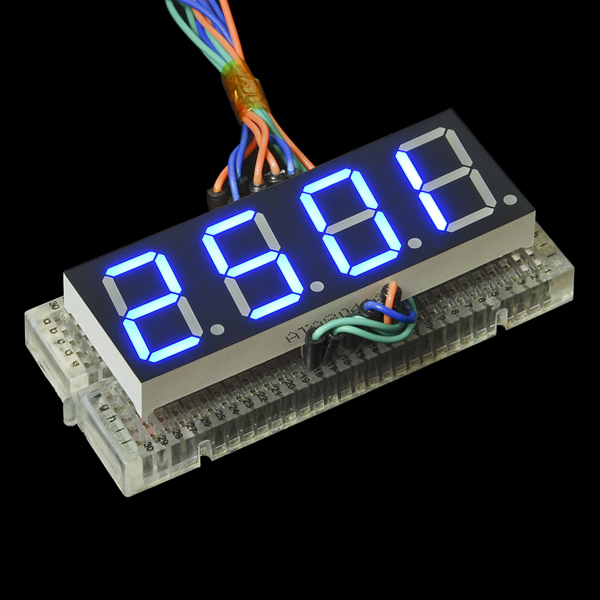
- 7-Segment Display - 20mm (Blue)

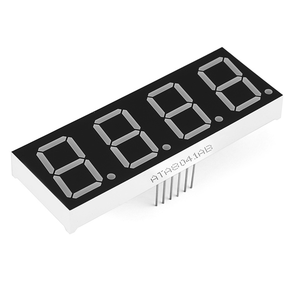
For a long time we've had small 7-segment displays and *huge *7-segment displays, but now we finally have something in between. These 20mm 4-digit 7-segment displays are big enough to see from a distance but not so big that you'd have trouble finding an enclosure for them.
These common-cathode displays feature 4 x 7-segment digits and one decimal point per digit. The LEDs have a forward voltage of 1.9VDC and a max forward current of 20mA.
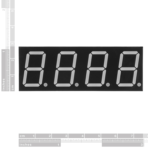
- 71.6 x 25.7mm
7-Segment Display - 20mm (Blue) Product Help and Resources
Using the Serial 7-Segment Display
August 13, 2013
How to quickly and easily set up the Serial 7-Segment Display and the Serial 7-Segment Display Shield.
Using OpenSegment
April 1, 2013
How to hook up and use the OpenSegment display shield. The OpenSegment is the big brother to the Serial 7-Segment Display. They run on the same firmware, however the OpenSegment is about twice as big.
Core Skill: Electrical Prototyping
If it requires power, you need to know how much, what all the pins do, and how to hook it up. You may need to reference datasheets, schematics, and know the ins and outs of electronics.
Skill Level: Competent - You will be required to reference a datasheet or schematic to know how to use a component. Your knowledge of a datasheet will only require basic features like power requirements, pinouts, or communications type. Also, you may need a power supply that?s greater than 12V or more than 1A worth of current.
See all skill levels
Comments
Looking for answers to technical questions?
We welcome your comments and suggestions below. However, if you are looking for solutions to technical questions please see our Technical Assistance page.
Customer Reviews
4.3 out of 5
Based on 3 ratings:
4 of 4 found this helpful:
easy to use after I figured out the pinout. works great
Fits perfectly on my breadboard. Buying this was great for learning one of the few ways led segment displays work to build on basic knowledge. Pin numbers are labeled for the schematic on the datasheet and pins 1 &12 are printed next to their pins underneath making it easy to figure out. Negative lead goes to digit selector and positive goes to letter(individual segment) that means only a single led segment is on at once. With the use of a microcontroller or equivalent you can rapidly change between which led segment is on. Because the rapid change happens faster than the eye can tell; it looks as if multiple leds are on. If you hook multiple letters/ digits up all at the same time you will be increasing current across a common node so keep in mind ohms law and the datasheet limits so you don't damage anything.
3 of 3 found this helpful:
Good value for a basic 7-Segment Display
This relatively inexpensive display works well after you know how it works. To that end, I published a basic hookup guide on hackster.io:
https://www.hackster.io/meljr/sparkfun-com-11408-4-digit-7-segment-display-hookup-guide-4b4d9e
Very cool display!
The only problem I have with the product is some sort of lack of documentation on it. The only data sheet available is in chinese and the pintout isn't even listed on it. I mapped it for whoever else wants to use this. Here it is:
Pin-out (looking at the digits as if it was installed on a breadboard, with the decimal points at the bottom):
12 11 10 9 8 7
1 2 3 4 5 6
Max 3V, don't forget your resistor!
Enjoy!
Description says Vf of 2.1V, but blue is more likely to be 3V or greater. Also would be helpful to put "common cathode or "common anode" in the description.
I think you might be commenting on the wrong product. The product description does state,
Also, the linked datasheet specifies a Vf = 2.99 - 3.10 V.
I wrote a library for this. The repo also includes a schema how to connect this display.
see https://github.com/renes/fourDigitLCDDisplay
Is there any plan for a serial backpack for these like the smaller ones???? I don't care if you have to put four SMD Darlingtons on it to handle the current/voltage issues....I buy the serial ones all the time, and they aren't near big enough, these are!
Yes, I said the same thing over on the Red version of this - SF please modify the Serial LED display to allow the pinout for this unit, that would be a much more useful product!
Can this be used outdoors without the display fading due to the sun?
The Eagle footprint for these are off. The Eagle part is ~2.497" wide however the part is 2.824" wide. The height is fine.
Has this been corrected yet? Is there an alternate library for them?
does this work with arduino and breadboard?
yes and yes; last picture shows one in a mini breadboard, and here's how you can hook up displays like these to an Arduino: Arduino 7 Segment 4 Digit LED Display Tutorial. Note that although the author references a SparkFun display, it may be an older model - so double-check which pins you need to connect where :)
Once you've got it up and running, you may wish to google around for documents on how to drive these using a shift register to reduce the number of pins you'd take up on your Arduino, or even look at the Serial 4-digit 7-segment displays on offer here.
I was able to get one of these working with a shift register to control the segments, but still used pins on my RedBoard to select digits. Can a shift register also sink current, link an Arduino GPIO pin, so that I could do the digit selection through the shift register too?
Most can, but you'd have to check the datasheet of the shift register you're using. Keep in mind that when you do this and display, say, the number 8, the pin on that shift register will have to be able to sink the current for all 8 unless you cycle through each of the segments. A far more common route is to put multiple shift registers in series so that you get a register big enough to cover all of the segments in your display set up. Google around - all roads lead to Rome.. it's just figuring out which Rome you want to go to that's the hard part :)
Thanks. I'm using the shift register available from SparkFun (TI chip), and while I couldn't decipher for sure from the datasheet, the fact that you said "some would" was enough for me to give it a try. It worked great. I wrote the code to do it both ways - cycling through digits, turning on all segments, then writing the registers AND cycling through the segments one at a time. Got about the same brightness on the segments either way. I started out using a 330ohm resistor for each digit cathode, but found that if I just connect directly to the shift register pin I get a bright display without frying the segment (blue LEDs).
My test code just counts from 1 to 9999, but I added in a delay between each segment that descends from 250 to 0 and then resets as each number in the count changes, so I get a nifty visual effect as the count approaches multiples of 250.
Just got a few blue and yellow of these to test out. Haven't done much other than bread board them to make sure everything lights up. In my setup I drove a particular segment (e.g. segment a or b) on all four digits simultaneously, then I would check segment b, c, d, etc. My multimeter gave me 2.35 mA draw for four leds (total, not each) using a 1 kOhm resistor. For any indoor application, the blue is easily visible only drawing 0.5 mA per segment continuous (5 V, 4.7 kOhm test resistor driving one segment). The yellow units are not as bright and draw more current (0.68 mA, 5 V, 4.7 kOhm), but I think the amber/gold color looks really good.
Edit: The yellow can be bright, but take more current. According to the datasheet specs blue @ Vf=3V, Ic=20mA, the yellow @ Vf=1.9V, Ic=30mA. But blue has twice the luminosity of yellow at half the current. They are both plenty bright enough though.
Are these SMD? Or are those pins on the bottom? Also, do you need a breakout board for it?
Has pins.
Yeah, I have the same question as Magnethead, a serial version of this like COM-11441 would be good.
1.9V forward voltage for blue LEDs? Aren't they usually in the ~ 3V range?
The actual forward voltage of the blue and white displays is 3.2V @ 20 mA.
you are right, common cathode shit in the datasheet it does say commun anode...
really COMMON ANODE!!!
That's what's in the previously posted datasheet. It seems the wavelength and all the specs except luminous intensity are the same as the red display. Copy & paste by the manufacturer?
Where is located the datasheet??
thank you! good night! marC:)
They removed it for the time being as the datasheet they had received was incorrect. D'oh. I'm sure somebody from SFE will reply to you once a correct datasheet is available.
Is there a kicad lib for this part?