- Home
- Product Categories
- 3-axis
- SparkFun Triple Axis Accelerometer Breakout - ADXL362

SparkFun Triple Axis Accelerometer Breakout - ADXL362
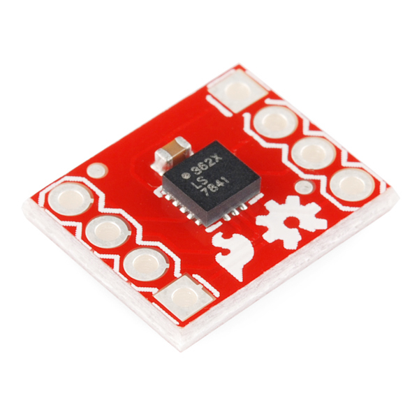
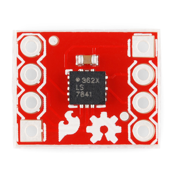
We've been using and selling Analog Devices' ADXL accelerometers for a good while now, and now we've found another great part in the series! The ADXL362 is a complete 3-axis MEMS acceleration measurement system that operates at extremely low power consumption levels. It measures both dynamic acceleration, resulting from motion or shock, and static acceleration, such as tilt. It's easy to communicate with the ADXL362 over SPI and built-in digital logic even enables autonomous operation for "wake-on-shake" operation.
We think this is a really cool device, so we spun up a breakout board! Now you can add low-power-consumption motion sensing to your next project!
- 3-Axis with Selectable Measurement Range: ±2, ±4, or ±8g
- Ultralow Power
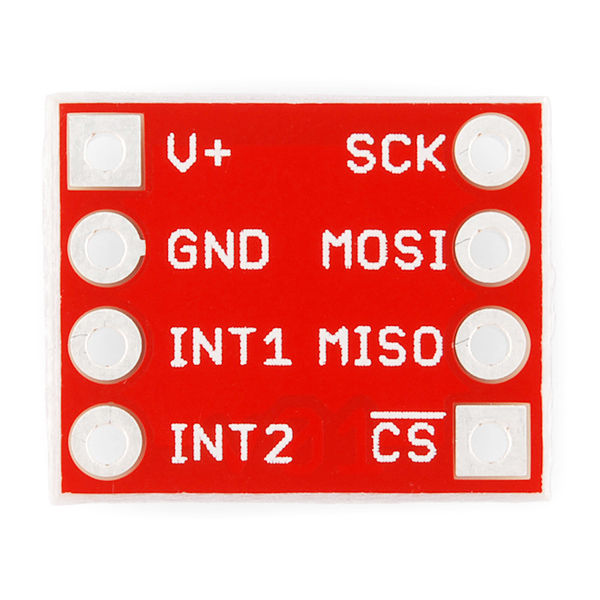
- SPI Digital Interface
- High Resolution: 1 mg/LSB
- Low Noise Down to 175 μg/√Hz
- Wide Voltage Range: 1.6 V to 3.5 V
- Adjustable Threshold for Motion Activation
- Measurement Ranges Selectable via SPI Command
SparkFun Triple Axis Accelerometer Breakout - ADXL362 Product Help and Resources
Core Skill: Soldering
This skill defines how difficult the soldering is on a particular product. It might be a couple simple solder joints, or require special reflow tools.
Skill Level: Noob - Some basic soldering is required, but it is limited to a just a few pins, basic through-hole soldering, and couple (if any) polarized components. A basic soldering iron is all you should need.
See all skill levels
Core Skill: Programming
If a board needs code or communicates somehow, you're going to need to know how to program or interface with it. The programming skill is all about communication and code.
Skill Level: Competent - The toolchain for programming is a bit more complex and will examples may not be explicitly provided for you. You will be required to have a fundamental knowledge of programming and be required to provide your own code. You may need to modify existing libraries or code to work with your specific hardware. Sensor and hardware interfaces will be SPI or I2C.
See all skill levels
Core Skill: Electrical Prototyping
If it requires power, you need to know how much, what all the pins do, and how to hook it up. You may need to reference datasheets, schematics, and know the ins and outs of electronics.
Skill Level: Rookie - You may be required to know a bit more about the component, such as orientation, or how to hook it up, in addition to power requirements. You will need to understand polarized components.
See all skill levels
Comments
Looking for answers to technical questions?
We welcome your comments and suggestions below. However, if you are looking for solutions to technical questions please see our Technical Assistance page.
Customer Reviews
5 out of 5
Based on 1 ratings:
Great little device
Works just as expected. Really low power consumption and fast refresh rate.
Please fix the link for the Arduino library on github: https://github.com/annem/ADXL362
This is a useful post for processing accelerometer data read in from the FIFO: https://ez.analog.com/thread/84039
Hello there..Iám using ADXL362 for my project. I have set the measuring range to 8g. When I calculate the acceleration one of the axis (changes according to movement) either shows full scale reading i.e close to 8g or Zero Reading. Is it Normal Behaviour for adxl362 or Iám doing something wrong.
An Arduino Library can be found here:
http://annem.github.com/ADXL362
Hi, I forked your Arduino library to correct a few problems I had with it, and for usage as Inclinometer :
https://github.com/pixelk0/ADXL362
Thank you very much for your initial work.
To see the raw values in the serial monitor, you need to change this line of code in the ADXL362.cpp line 20
to
save ADXL362.cpp and recompile
Thanks, looks good!
I've been prototyping with this breakout board and have stumbled across something that I'm still struggling to believe... It would appear that the device is photosensitive!
Let me explain, once calibrated the XYZ values appeared to behave themselves in my office, with Z showing approximately 1g and XY at roughly 0g when "horizontal".
The device is attached to a small UAV project that I'm working on which requires outdoor testing. During this testing I could not get the accelerometer associated part of the project to work as expected. After some analysis I discovered that the XYZ "bias" values were significantly shifted during flight testing.
Initially I decided that the vibration from the UAV's motor was causing the issue and that I either had to mount it differently or use a part with a better "vibration rectification" specification (this in itself was an illuminating learning experience).
It turns out that after some analysis, the ADXL362 was well within specification with respect to the vibration levels. So the problem was somewhere else... After lot's of code checking, and test flights designed to log the accelerometer outputs etc. I discovered that the bias levels changed abruptly as soon as I took the UAV outside into direct sunlight. I should also add at this point that the PCB on which the breakout board is mounted is exposed.
So was it temperature related? No... (more testing) However by using a small "hand operated sun shade" to cover only the breakout board I could instantly (within one sample period) modulate the bias values on all axes (by approximately 1g for the Z axis and by similar amounts for X and Y). This was a big surprise! So much so that I that I had to get a colleague up to speed on the experiment and convince him of the effect.
Other than the accelerometer there is only a single ceramic decoupling capacitor on the breakout board, I doubt that this capacitor is causing the effect. I checked on the AD web site and discovered that the black packaging used on the ADXL362 is made from "slica" with 5% added black carbon. i.e. a compound that is not completely opaque to infra-red, of which the Sun produces plenty!!
Has anyone else noticed this behavior?
I've lodged a support query with AD, but have not yet heard back.
Hi All, After setting up my sparkfun breakboard-mounted ADXL362, and having seen g's about 1.3 while still, I decided to run the self-test on it.
I am not too experienced with programming these babies, so please point me to any noob's mistake I might be running into.
I followed the instructions in the datasheet and set it up with precision +/-8g's, 100Hz, normal operation (no noise reduction) and no anti-aliasing. It runs on under 3v on an nRF51 DK board.
I executed this method:
void do_self_test() { uint32_t err_code; uint8_t inBuffer[8];//first two are padding, rest if for 6 uint's uint8_t regIn; /* Self-Test Output Change Min Typ Max XOUT 230 550 870 mg YOUT -870 -550 -230 mg ZOUT 270 535 800 mg */ SEGGER_RTT_printf(0, "\r\nSelf testing...\r\n", regIn); nrf_delay_ms( 1000 ); MK_SPI_ReadRegs( MK_ACC_REG_XDATA_L, 6, inBuffer ); fifo_in_good[0].x = processPairOfUints12BitsSigned( inBuffer[2], inBuffer[3] ); fifo_in_good[0].y = processPairOfUints12BitsSigned( inBuffer[4], inBuffer[5] ); fifo_in_good[0].z = processPairOfUints12BitsSigned( inBuffer[6], inBuffer[7] ); int16_t xG = fifo_in_good[0].x; int16_t yG = fifo_in_good[0].y; int16_t zG = fifo_in_good[0].z; xG *= 4;//to mg's yG *= 4;//to mg's zG *= 4;//to mg's SEGGER_RTT_printf(0, "Original = %03x %03x %03x = %04d %04d %04d; mG = (%d, %d, %d)\r\n", fifo_in_good[0].x, fifo_in_good[0].y, fifo_in_good[0].z, fifo_in_good[0].x, fifo_in_good[0].y, fifo_in_good[0].z, xG, yG, zG );
MK_SPI_WriteReg( MK_ACC_REG_SELF_TEST, 0xFF );
// wait 4/ODR nrf_delay_ms( 40 );
int16_t xGacc = 0; int16_t yGacc = 0; int16_t zGacc = 0; for(int i= 0; i < 8; i ++) { MK_SPI_ReadRegs( MK_ACC_REG_XDATA_L, 6, inBuffer ); fifo_in_good[0].x = processPairOfUints12BitsSigned( inBuffer[2], inBuffer[3] ); fifo_in_good[0].y = processPairOfUints12BitsSigned( inBuffer[4], inBuffer[5] ); fifo_in_good[0].z = processPairOfUints12BitsSigned( inBuffer[6], inBuffer[7] ); int16_t xGaux = fifo_in_good[0].x; int16_t yGaux = fifo_in_good[0].y; int16_t zGaux = fifo_in_good[0].z; xGaux *= 4; yGaux *= 4; zGaux *= 4; SEGGER_RTT_printf(0, "Reading %d = %03x %03x %03x = %04d %04d %04d; mG = (%d, %d, %d)\r\n", i+1, fifo_in_good[0].x, fifo_in_good[0].y, fifo_in_good[0].z, fifo_in_good[0].x, fifo_in_good[0].y, fifo_in_good[0].z, xGaux, yGaux, zGaux ); xGacc += xGaux; yGacc += yGaux; zGacc += zGaux; } // Div by 8 xGacc /= 8; yGacc /= 8; zGacc /= 8; SEGGER_RTT_printf(0, "Final mG = (%d, %d, %d)\r\n", xGacc, yGacc, zGacc ); SEGGER_RTT_printf(0, "Delta mG = (%d, %d, %d)\r\n", xGacc - xG, yGacc - yG, zGacc - zG ); SEGGER_RTT_WriteString(0, "Done!\n" );
MK_SPI_WriteReg( MK_ACC_REG_SELF_TEST, 0x00 );
while( true ); }
Running it results in the following output (please don't mind the console's bug when formatting ints as hex):
Resetting device... Read ID0 + 3 = 0xFFFFFFAD, 0x1D, 0xFFFFFFF2, 0x02. FIFO_CTL = 0x0A, FIFO_SAM = 0xFFFFFFFF FILTER_CTL = 0x83 POWER_CTL = 0x02
Self testing... Original = 01F 018 153 = 0031 0024 0339; mG = (124, 96, 1356) Reading 1 = 143 FFFFFEE3 258 = 0323 -285 0600; mG = (1292, -1140, 2400) Reading 2 = 143 FFFFFEE3 258 = 0323 -285 0600; mG = (1292, -1140, 2400) Reading 3 = 143 FFFFFEE3 258 = 0323 -285 0600; mG = (1292, -1140, 2400) Reading 4 = 143 FFFFFEE3 258 = 0323 -285 0600; mG = (1292, -1140, 2400) Reading 5 = 143 FFFFFEE3 258 = 0323 -285 0600; mG = (1292, -1140, 2400) Reading 6 = 143 FFFFFEE3 258 = 0323 -285 0600; mG = (1292, -1140, 2400) Reading 7 = 143 FFFFFEE3 258 = 0323 -285 0600; mG = (1292, -1140, 2400) Reading 8 = 143 FFFFFEE3 258 = 0323 -285 0600; mG = (1292, -1140, 2400) Final mG = (1292, -1140, 2400) Delta mG = (1168, -1236, 1044)
According to the datasheet, the delta in mg's is way off (by about a factor of 2). Does this mean my 362 is out of combat? or am I doing something wrong in the test procedure? If it were indeed kaput, is it covered by any sparkfun guaranty?
Thanks in advance for any clues you may provide me with.
Regards,
M.
Hi
I'm running this reasonably successfully with the Uno, and have got motion activated sleep example from the library working. (I had to put a lot of the code in the cpp file into my actual sketch, though).
BUT the device is not ultra-low power. It draws about 0.35mA, regardless of whether it's awake or asleep. This is far more than the datasheet says. I can't see anything in the datasheet that allows you to put it into a lower power consumption mode.
Any ideas?
A driver for Netduino can be found here: http://forums.netduino.com/index.php?/topic/10796-adxl362-triple-axis-accelerometer-driver/
Has anyone created a Fritzing part for this breakout? Need to document something, but I'm relatively new to Fritzing.
What is the measure unit of the sensor readings? G or mG? Thanks.
1mG/count, in the 2g range.
My readings show
"XDATA = -1 YDATA = -1 ZDATA = -1 Temperature = -1"
and do not change. Any idea as to what I'm doing wrong?
Most likely you're completely failing to communicate with the chip.
Check your connections and make sure everything's set up right. If you're still having issues you can contact tech support.
How i can read the data, and compare it? example:
if(XValue>=0) {Serial.print("Hello World");}
I only want compare the data output and I dont know which or how with this arduino library.
I'm using the ADXL362 library along with my Arduino Uno. All connections are sound and x,y,z readings are flowing. Can anyone guide me on how to convert these readings (accelerations) into angle/degrees?
Most universities should have a little page describing the calculations, but one example is here. It's math intensive if you do it by hand-I'd recommend checking the Arduino forum for example code someone may have written to handle the computations for you.
Thanks Toni_K! Lemme be more clear though... what is the max and min value I could see on the Arduino digital pin? In other words if I knew x could only equal -64000 through 64000 I could do some basic division to get me the meaningful value I need. Guess it's more of an Arduino/SPI question than calculation question. Thanks!
Ah, gotcha. Sorry for the misunderstanding. That would simply be a matter of reading the registers for each axis and again, translating that to a usable value of acceleration. The pertinent information for this is going to be in the datasheet for the sensor. Keep in mind though that acceleration is not the same as position/orientation. You're still going to need to do some derivations to get the angles from the acceleration readings.
I would like to know if this purchase come with the breakout board and the ic ? And is that all are already assembled (welded) ?
Just received the ADXL362 and have it wired up to an Arduino 2560. Ran the Arduino library example linked above and have the following results:
Soft Reset
Setting Measeurement Mode - Reg 2D before = 0, Reg 2D after = 0
Start Burst Read of all Control Regs - Library version 6-24-2012: Reg 20 = 0 Reg 21 = 0 Reg 22 = 0 Reg 23 = 0 Reg 24 = 0 Reg 25 = 0 Reg 26 = 0 Reg 27 = 0 Reg 28 = 0 Reg 29 = 0 Reg 2A = 0 Reg 2B = 0 Reg 2C = 0 Reg 2D = 0 Reg 2E = 0
Obviously not correct. Any ideas what I did wrong? Or is the ADXL362 been hosed?
I had the same thing. I had Slave Select on pin 53, which I got from reading the SPI material on the arduino site. I read the ADXL362.cpp file and found that they had SS on pin 10. So I changed that to pin 53. I also had issues correctly changing the logic level from 5V to 3.3. But everything is working now. Hope that helps
So I switched over to my STK600 with an AtMega2560. Wired everything correctly according the docs, running the STK600 at 2.0V. Attempted to read the DEVID from the device with the following bytes sent in order: 0x0B 0x00 0x00. The result after the 3rd byte was 0xFF which is incorrect. Verified everything with a scope to make sure bytes sent and received. MOSI looks good going out, MISO shows all high during the 3rd clock sequence for the 3rd byte transfer. I also have a ADXL345 which I have successfully been able to wire up and run, no problems. Any help appreciated.
I've wired this up following the tutorial that comes with the library, but when I run the test sketch with the device resting on the table, it just spits out semi random sequences of numbers:
XDATA = -32 YDATA = 792 ZDATA = 448 XDATA = -289 YDATA = 272 ZDATA = 688 XDATA = -799 YDATA = 524 ZDATA = 688 XDATA = -285 YDATA = 272 ZDATA = 1196 XDATA = -32 YDATA = 272 ZDATA = 1204 XDATA = 224 YDATA = 524 ZDATA = 1188 XDATA = -285 YDATA = 280 ZDATA = 1204 XDATA = -285 YDATA = 780 ZDATA = 448 XDATA = -32 YDATA = 512 ZDATA = 688 XDATA = -32 YDATA = 272 ZDATA = 700 XDATA = 224 YDATA = 272 ZDATA = 688 XDATA = 224 YDATA = 280 ZDATA = 700
There's sort of a pattern in the same numbers returning, but I would expect values around 0. When I move it, there is definetely a change in the sequence, so it is picking up some sort of acceleration. When I run it in 8-bit mode, it seems a bit more stable, but still unexpected reading, especially for X:
XDATA = 254 YDATA = 0 ZDATA = 8 XDATA = 254 YDATA = 0 ZDATA = 8 XDATA = 254 YDATA = 0 ZDATA = 8 XDATA = 252 YDATA = 0 ZDATA = 8 XDATA = 252 YDATA = 0 ZDATA = 8 XDATA = 254 YDATA = 0 ZDATA = 16 XDATA = 254 YDATA = 0 ZDATA = 8 XDATA = 252 YDATA = 0 ZDATA = 16 XDATA = 254 YDATA = 0 ZDATA = 8 XDATA = 254 YDATA = 0 ZDATA = 8
I'm running it at 3.3V from a Pro Mini 168, 8Mhz. Is it broken or did I zap it when soldering the pins on?
I had a similar display on mine. I also noticed the display showed "Reg 2D after = 0" not 2 as expected.. I found that the ground to the device was open due to a bad socket on the breadboard. once it had a good ground it work as shown in the HOW - TO
I bought one of these planning to use it with a TI MSP430 Launchpad board; turns out the board runs at 3.6V, and not 3.3V as I had thought. The ADXL362 datasheet lists a maximum operating voltage of 3.5V and an absolute maximum rating of 3.6V. Does anybody know if it's likely to work without problems, or do I need to do some level translation? Would a diode on each supply and I/O line be enough to do the job?
Diodes would be a reasonable quick-and-dirty way to interface this board to the 3.6V Launchpad. Use them on the power supply and any I/O line going -to- the ADXL362 (the ones coming back won't be a problem). That should bring all the voltages into spec. There's a good chance that it would work fine at 3.6V, but personally I take datasheet numbers seriously. Good luck!
Will you have just the adxl362 available without the board?