- Home
- Product Categories
- Kits
- Qtechknow ArduSensor Learning Kit

Qtechknow ArduSensor Learning Kit
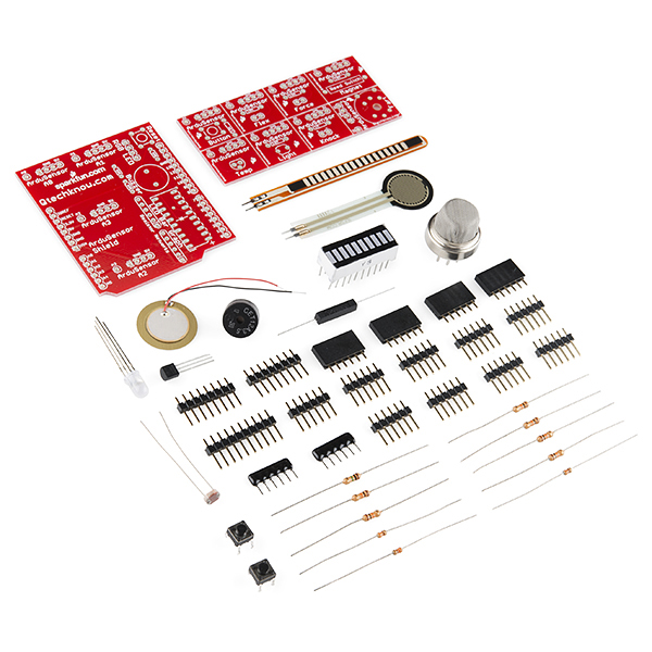
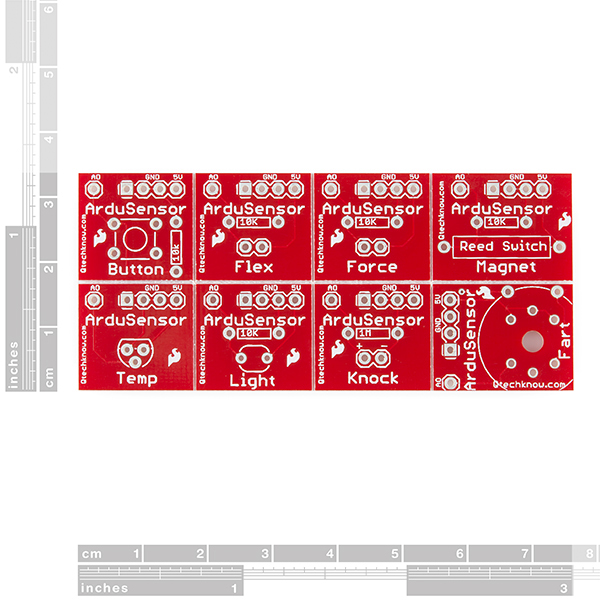
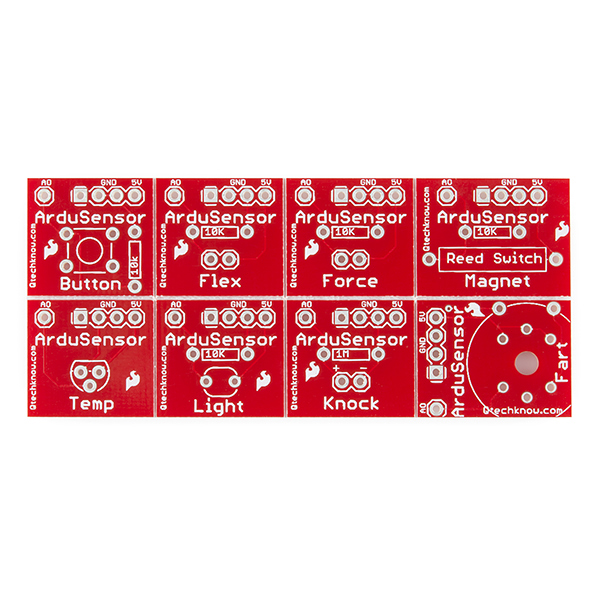
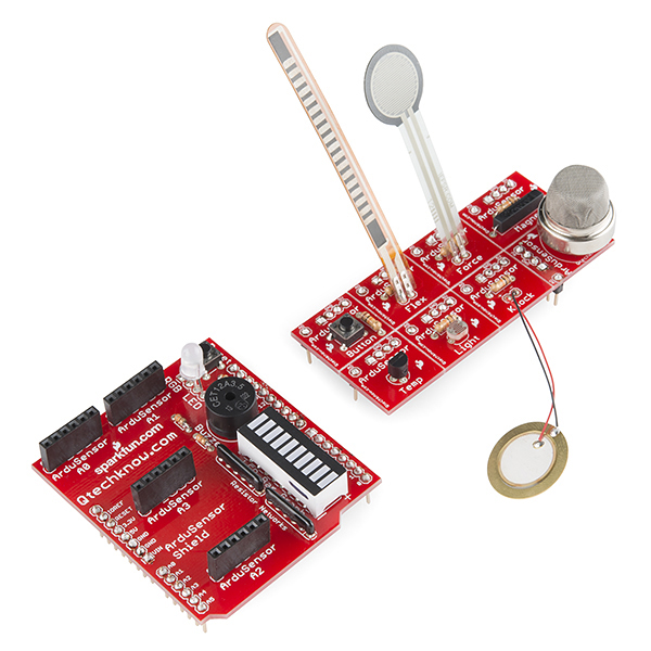
Have you always been curious about sensors but never knew where to start? The Qtechknow ArduSensor Learning Kit for Arduino is a fantastic option! Inside the kit are two boards, one an ArduSensor shield and the other a conglomeration of eight smaller boards that are v-scored between one another making it easier for you to solder all the sensors in first and then break apart at your own leisure.
This kit boasts eight different types of sensors, including button, flex, force, magnet, temperature, light, knock, and (of course) fart. These sensors, once soldered, can easily be placed onto the ArduSensor Shield in one of four designated areas with readings from an RGB LED, a buzzer, and an LED bar graph relaying the information to you.
This comes in kit form and must be soldered together by the end user. Please note - we do not ship assembly instructions, but you can find an assembly guide below!
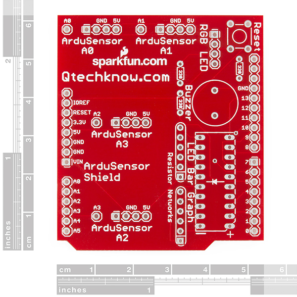
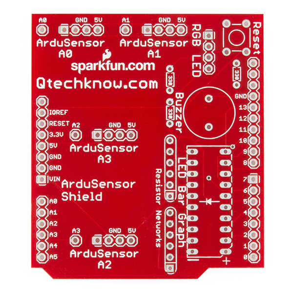
Note: The silk labels for ArduSensor A2 and A3 are reversed. The actual pin labels are correct next to the headers, use those for reference.
**Note: **This product is a collaboration with Quin at Qtechknow.com. A portion of each sales goes back to him for product support and continued development.
- 1x ArduSensor Shield PCB
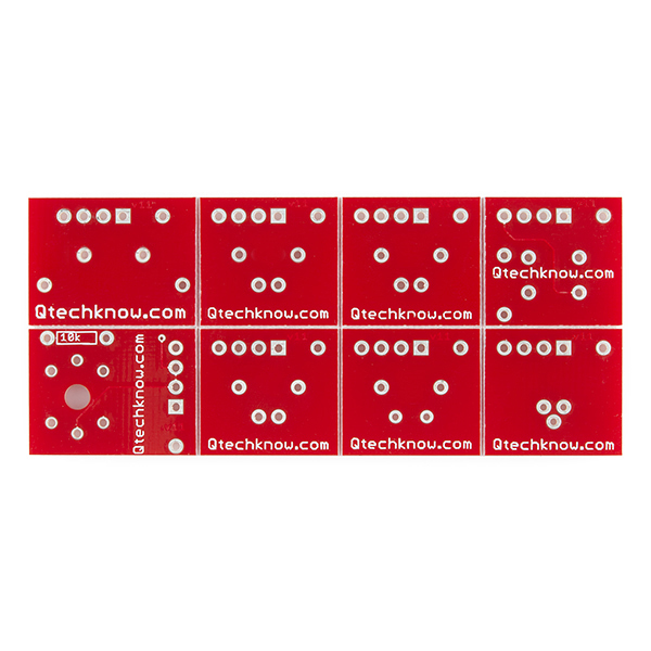
- 1x ArduSensor v-scored PCB
- 1x Methane CNG Gas (Fart) Sensor
- 1x Piezo Element (Knock)
- 1x Mini Photocell (Light)
- 1x TMP36 Sensor (Temperature)
- 1x Reed Switch (Magnet)
- 1x Force Sensitive Resistor (Force)
- 1x Flex Sensor (Flex)
- 1x LED Bar Graph
- 1x Piezo Speaker 2.048 KHz
- 1x RGB LED
- 2x Push Button Switch
- 1x 1M Ohm Resistor
- 3x 330 Ohm Resistor
- 6x 10k Ohm Resistor
- 2x 330 Ohm Resistor Network - 6-pin
- 4x M/F Headers - 6-pin
- 12x M/M Headers (1x 10-pin, 2x 8-pin, 9x 6-pin)
- [Schematic](http://cdn.sparkfun.com/datasheets/Kits/ArduSensor Shield-v11.pdf) (ArduSensor Shield)
- Schematic (Sensor Board)
- [Eagle Files](http://cdn.sparkfun.com/datasheets/Kits/QTech Learning Sensors Kit v11 Eagle.zip)
- Product Page
- Assembly Guides
- Product Video
- GitHub
Qtechknow ArduSensor Learning Kit Product Help and Resources
Core Skill: Soldering
This skill defines how difficult the soldering is on a particular product. It might be a couple simple solder joints, or require special reflow tools.
Skill Level: Rookie - The number of pins increases, and you will have to determine polarity of components and some of the components might be a bit trickier or close together. You might need solder wick or flux.
See all skill levels
Core Skill: DIY
Whether it's for assembling a kit, hacking an enclosure, or creating your own parts; the DIY skill is all about knowing how to use tools and the techniques associated with them.
Skill Level: Noob - Basic assembly is required. You may need to provide your own basic tools like a screwdriver, hammer or scissors. Power tools or custom parts are not required. Instructions will be included and easy to follow. Sewing may be required, but only with included patterns.
See all skill levels
Core Skill: Electrical Prototyping
If it requires power, you need to know how much, what all the pins do, and how to hook it up. You may need to reference datasheets, schematics, and know the ins and outs of electronics.
Skill Level: Rookie - You may be required to know a bit more about the component, such as orientation, or how to hook it up, in addition to power requirements. You will need to understand polarized components.
See all skill levels
Comments
Looking for answers to technical questions?
We welcome your comments and suggestions below. However, if you are looking for solutions to technical questions please see our Technical Assistance page.
Customer Reviews
No reviews yet.
You had me at "fart sensor".
I bought 4 kits 11470 (for my students) and, like "Larsi", I have 4 common anode RGB leds instead of common cathode leds. Please, tell me what you can do for me. Best regards.
Please contact tech support and they will get you replacement parts ASAP.
Hi Quin, I am having problems opening up example code from the Qtech site. Any example code with the prefix "AS-" in the title, the arduino IDE software will not open it ( it doesn't matter what IDE version I use to try to open it ). It barks back with all kinds of JAVA errors. Any example code without the "AS-" in the title opens fine. Would it be possible for you to post a visual of all the code examples so that all I need to do is copy & paste the code into the Arduino IDE software? I'm using IDE versions 0022 all the way up to 1.0.5 on a windows Vista platform in case your curious. Thanks sir.
Hi Rod222,
I just fixed the problems with the links (I'm not sure why Java didn't like it, when I tested all of the code ~6 months ago, it seemed to work fine). In any version of the Arduino IDE 1.0 or above (because this version uses the .ino format), or on any operating system, it should work now for all of the products. Try downloading the code again, and it should work. Hope this helps.
Thanks! Qtechknow
Is there example code somewhere? github repository from the product page is de nada.
You'll find the example code on the ArduSensor Shield assembly guide page (http://learn.qtechknow.com/tutorials/30), near the end. It'll show you how to make a quick circuit using some of the ArduSensors as well as the shield. For example code for the individual ArduSensors, you can go to learn.qtechknow.com, and click the appropriate guide for assembly details and code. Hope that helps!
Thanks! Quin
do you have to get a tool such as the FDI basic breakout in order to program this tool?
ArduSensors are like 'mini-shields' for Arduino, so you would only need the FTDI board if your Arduino required it (ex: Arduino Pro).
I believe that the Schematic for the ArduSensor Shield is incorrect. Two of the LEDs in the bar LED are actually on A4 and A5 -- not A0 and A1. Also, the nets for JP1-4 are incorrect, because they don't match the silk screening on the board.
Also, I'm disappointed that, like Larsi mentioned below, I got the wrong RGB LED.
To me, this product doesn't quite match up to what is advertised.
SparkFun: I think you put the wrong RGB diode in the kit. There should have been a common cathode, but you used a common anode. I cannot get the LED to work, but if I connect 5v the the shield ground and gnd (with a resistor) to pin 3, 5, or 6 it works! Suggestions?
Our BOM does specify a common cathode LED, you might have just gotten the wrong one. Our techsupport team should be able to get that taken care of.
Thanks for the new LED - I put it in an it worked right away. Great customer service!