- Home
- Product Categories
- SparkFun
- SparkFun AutoDriver - Stepper Motor Driver (v10)

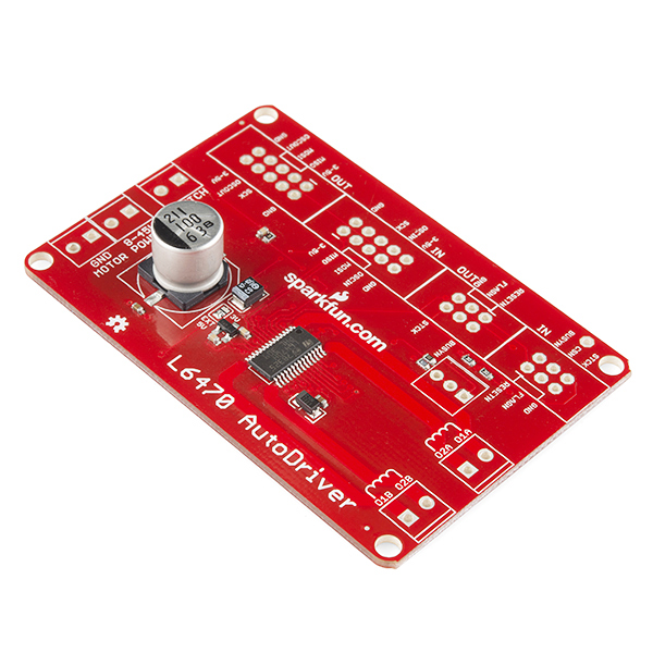
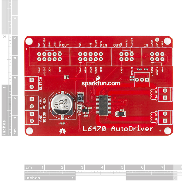
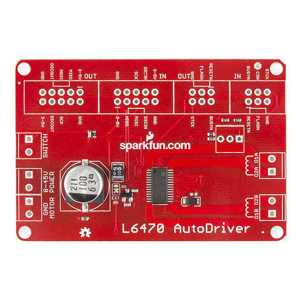
SparkFun AutoDriver - Stepper Motor Driver (v10)
The SparkFun AutoDriver makes it easy to put the L6470 Stepper Driver (a.k.a "dSPIN") to work in your project. Simply connect your motors and your SPI-capable microcontroller and get steppin'!
STMicro's L6470 is a 3A, 8-45V bipolar stepper motor driver. It has built-in overcurrent detection, undervoltage detection, overtemperature detection, stall detection, a 5-bit ADC, and a switch input that can be used for either user jog control or as a hard stop function. As if that weren't enough, it also features microstepping support (up to 128 microsteps per full step) and PWM drive voltage limiting.
Unlike most stepper motor drivers, the dSPIN is controlled over an SPI link. It has an on-board 16MHz oscillator which allows it to autonomously execute movement commands. That means no more counting steps in your code! It also supports customized acceleration and deceleration profiles to prevent jerky starts and stops. On-board registers track current speed and location.
The logic supply voltage supports both 3.3V and 5V I/O levels.
- Supports up to 128 Microsteps per Full Step
- Over-Temperature Detect
- Over-Current Detect
- Under-Voltage Detect
- PWM Drive-Voltage Limiting
- SPI Controlled
- On-Board Oscillator and Speed/Location Registers
- Stall Detection
- 5-bit ADC
- [Schematic](http://cdn.sparkfun.com/datasheets/Robotics/L6470 AutoDriver_v10a.pdf)
- [Eagle Files](http://cdn.sparkfun.com/datasheets/Robotics/L6470 AutoDriver.zip)
- Datasheet (L6470 dSPIN)
- Hookup Guide
- AutoDriver Library
- GitHub (Library)
- GitHub
SparkFun AutoDriver - Stepper Motor Driver (v10) Product Help and Resources
Core Skill: Soldering
This skill defines how difficult the soldering is on a particular product. It might be a couple simple solder joints, or require special reflow tools.
Skill Level: Rookie - The number of pins increases, and you will have to determine polarity of components and some of the components might be a bit trickier or close together. You might need solder wick or flux.
See all skill levels
Core Skill: Robotics
This skill concerns mechanical and robotics knowledge. You may need to know how mechanical parts interact, how motors work, or how to use motor drivers and controllers.
Skill Level: Experienced - Your experiences should include working with stepper motors and feedback system. You may need to understand how encoders and more complex control systems work.
See all skill levels
Core Skill: Programming
If a board needs code or communicates somehow, you're going to need to know how to program or interface with it. The programming skill is all about communication and code.
Skill Level: Competent - The toolchain for programming is a bit more complex and will examples may not be explicitly provided for you. You will be required to have a fundamental knowledge of programming and be required to provide your own code. You may need to modify existing libraries or code to work with your specific hardware. Sensor and hardware interfaces will be SPI or I2C.
See all skill levels
Core Skill: Electrical Prototyping
If it requires power, you need to know how much, what all the pins do, and how to hook it up. You may need to reference datasheets, schematics, and know the ins and outs of electronics.
Skill Level: Experienced - You will need to consult a datasheet for calculations to determine a components output format, linearity, and do a little math to get what you need. You will be using a datasheet or schematic beyond basic pinouts.
See all skill levels
Comments
Looking for answers to technical questions?
We welcome your comments and suggestions below. However, if you are looking for solutions to technical questions please see our Technical Assistance page.
Customer Reviews
5 out of 5
Based on 2 ratings:
3 of 3 found this helpful:
Super Noob Arduino Uno Get Started Guide
After you have your hookups soldered on, use the "SparkFundSPINexample" code to begin. The 1st defines within that example will tell you which pins goto what numbers on the arduino board. Pins 16 & 17 are A3 and A4 respectively. Know your stepper motor's needed RMS amps, resistance per lead, and rated voltage. Look up the ST voltage mode control guide (direct link http://goo.gl/d8QJri, or lookup EVAL6470H & it will have the link to it) on page 10 it will have the equations to calculate your gains for running, accelerating, decelerating, and holding. Additionally it has tons of useful information of how the chopper motor driver works. once you've calulated your gains, look for the dSPIN_SetParam(dSPIN_KVAL_RUN) function and put your calculated gains IN HEX, adding additional copies of the function call to set the rest of the gains (HOLD, ACC,DEC) under the dSPIN_SetParam(dSPIN_MAX_SPEED) function, change the MaxSpdCalc() to the total number of FULL STEPS/SEC i.e. if your stepper has a step size of 1.8deg then MaxSpdCalc(1) will give you 1.8deg/sec. Under the dSPIN_SetParam(dSPIN_STEP_MODE) call, check the dSPIN_STEP_SEL_1_16 and set it to a number of microsteps per full step you want (see SparkFunL6470.h for choices available). Finally, in the loop, use the dSPIN_Move function and the number of steps input is the number of MICROSTEPS, NOT FULL STEPS. ,so calculateh ow much you want to move it, and put a direction in. They use a while "(digitalRead(dSPIN_BUSYN) == LOW);" to keep it from jumping to the next command, but i had to additionally add a "delay(1000)" after the softstop() command to ensure it didn't immediately move to the next moment. Good luck! this was the bare minimum I needed to get this working, use the smallest amount of voltage you can bear to avoid blowing up the board (minimum 8V from the board, even if your motor is rated 6V). [WARNING: THIS STEPPER DRIVER HAS A SINUSOIDAL CURRENT, NOT ALL POWER SUPPLIES (mine included) WILL REPORT TOTAL RMS AND INSTEAD WILL ONLY REPORT POSITIVE RMS. IF YOU ARE PULLING MORE THAN 1.5 AMPS YOU ARE GOING OVER THE RMS RATING OF THE DRIVER, ADDITIONALLY YOU HAVE TO CHECK YOUR OVERCURRENT DETECTION TO COMPENSATE FOR THE SINUSOIDAL CURRENT (+/- 1.5 amps needs over 3kmilliamps overcurrent)]
5 of 7 found this helpful:
Beefy driver with loads of features
This driver, as per the description, lets you offload the stepper complexity (acceleration/speed control, step counting) to it rather than deal with it in your program, which is super helpful for driving multiple motors. I have not chained them together, but the tutorial shows how to do this and how to set up the boards (they need lots of boilerplate code to start).
Also: ATTENTION ARDUINO MEGA USERS: The libraries provided for the autodriver are excellent, however the .ccp files have hard-coded references to the SPI pin numbers on the Uno. In order for this board to function on the Mega, you must edit the files to use the SPI pin numbers on the Mega. Hopefully this will save someone some time (it would have saved me a few hours...).
URGENT HELP REQUIRED GUYS!
I'm using the Autodriver to power a gauge needle stepper motor. It is powered by a 12V DC 20A power supply. It's been working fine for several months, but then suddenly it burnt the L6470 chip after turning it on yesterday. I replaced the Autodriver with another one - it worked several times and then burnt that one too. I have kept the Overcurrent shutdown to 'DISABLED', but it had been set to that for a long time without any problem. Also the voltage compensation is disabled too, im not sure whether that would make a difference though. Lastly I'm using maximum KVA's for acc, dcc, holding and running since thats how my motor works best. I would appreciate if anyone can decipher whats happening here.
I think it's pretty simple: you're overcurrenting the chip badly. What are the ratings on the motor? You're going to see some fairly high surge current during power-up. It might help to reduce the KVAL for hold to some relatively low level (by "gauge needle stepper motor", I assume your motor is driving a needle on a gauge, so the load is ~0). That will at least reduce the current during static periods which will give you a better life on everything.
Also, before you hook up another driver, ohm out the windings on your motor and make sure they are reasonable. The resistance of each winding should be Vrated/Irated (+/- a few %); if it's lower than that, you've damaged your motor (not unreasonable if you've been running 100% hold current through the motor and the motor isn't rated to handle it). That would explain why the driver failed suddenly, and why the second one failed suddenly as well. You may need to replace the motor, too.
hello i am facing some problem with this board. when i try first motor with 12 volt and 400 mA. everthing went smooth.the driver was working great. when i try the second motor with 24 volt and 1.8 A then i got the Flag pin High. the code is the same. even that threashhold current is 6000ma.
It sounds like you may be momentarily exceeding the current limit. 24V is a pretty high voltage; what's the voltage/current rating on the motor? My experience has been that it's pretty easy to exceed that voltage during acceleration and deceleration, even if you're safely in range during run. You might try dialing the KVAL settings down some during acceleration and deceleration.
Hi there,
is there a chance for an stp or stl file of this board?
Hi there, i am trying to drive a pretty hefty stepper motor (6V, 3A) with this board. I did the simple hookup using the schematic near the end of the hookup guide, & just uploaded & ran the basic music player as is, & with the references to motorB commented as well. I did not see any motion from my motor or any current being pulled from my power supply. Then, i tried making my own simple sample code to just see if i can get the motor running & still an unable to see any amperage being pulled. I checked my signals with the board running & see 5V across Pwr & ground, 1.8V across gnd & MISO, 5V across gnd & SCK, .003V across gnd & MOSI, & 5V across grd & CSN. With the power supply on i see 7.3 V (what i set the power supply to) to the external ground & power. If i check the the stepper motor output terminals, i see no voltage across them & ground. This imgur link has pictures of my setup & my basic code: http://imgur.com/a/rAagy. Ive checked the continuity of all of my soldering & ensured no crossed signals. Any help would be appreciated.
Hello,
I could read quite scaring things about BEMF produced by motors during deceleration phases going up through the power lines and frying other components around. Some posts suggest adding a Schotky diode on each dSPIN power line to block them.
The original poster was using a DC/DC for producing the supply voltage, and he had 3 of them fried because of reverse voltages above max specs.
In a configuration where the motor supply is produced by a basic high current rectifier bridge filtered by a big capacitor (50V/10 000uF), do I need to pay attention to this ? I would be very annoyed seeing the 5 other dSPINs used in my configuration being killed one after the other ;-)
Any advice ?
I plan to use 6 Autodrivers to control a robotic arm. An often needed situation is to start the moves of several joints (i.e. motors) at the exact same time.
Ideally a "deferred move" command would be used to send the move to be executed at a later time to each motor in turn, and then a "execute pending" sent to all of them (toggling their respective CS line in a synchronized way) would trigger all motors at the same time. Dynamixel digital servos for instance offer this way of controlling several motors in a synchronized way.
Unfortunately we don't have such commands with the dSPIN. What would be the best approach to come close to the expected result ?
Maybe the execution time of the code sending the move command to all involved motors in turn will be short enough so that the delay between each start will be negligible, but this does not satisfy me fully. I'd like to be able to write the control software in Python (on a Raspberry) for a lot of reasons, and I'm afraid to have some timing issues there.
Any suggestion will be appreciated.
There are two things you probably want to do here:
Sadly, the pinout of the headers isn't ideal for this on this version; we're working on a rev to make this a little better.
The basic idea is that you treat each board as a shift register by asserting CS, clocking one byte of data in per board, then de-asserting CS to latch those bytes. Once a command has been completed, all of the boards will begin doing their thing at the same time, and since they're all running on the same clock, they should stay in sync.
This is outside the current scope of examples for this product, and it's not trivial, but I do think it's possible. One thing that may cause issues is the complexity of non-linear pulse trains. I think some of that can be managed using the acceleration settings but I haven't proven that out yet.
Thanks for replying so quickly ;)
You mean "by using OSCIN and OSCOUT pins" ?
How can this be done since the L6470 requires CS to be toggled for each byte of data ?
[EDIT] found the reply. I finally understood the meaning of fig. 18 of the datasheet. It worth trying. There is some preparation to be done to fill command trains with nops when all the motors are not supposed to receive the same command (e.g. make only 3 of 6 move), but it seems feasible. I understand now why STM engineers have chosen what appears first as an unconventional way of using CS (i.e. de-asserting after each byte, and not after the whole message). They are really smart people ;)
I'm not sure to get your point here. What you propose seems to make it possible to have all moves start at the same time.
How the non-linearity of pulse train (I guess you refer to the pulses at the coils level) comes into play here ?
Yes, use the OSCIN and OSCOUT pins. One of the settings for the oscillator is "Use internal oscillator and output on OSCOUT pin", and another is "Use OSCIN pin, pass to OSCOUT pin". By having the first board generate a clock and send it to the 2nd, the second to buffer and resend to the third, etc, you ensure that they are all roughly in sync (there will be some nanoseconds of propagation delay, of course, but they'll be in phase with one another).
If you don't toggle the CS pin after shifting a byte in, that byte shifts out the data out pin. If you have 6 boards, and data out of the first feeds data in of the second, and so on, then when you clock out 6 bytes with CS asserted, the first byte clocked out will end up in the last board's input buffer, the second byte in the second to last board's buffer, and so on. Thus, you can load a value into each of the six boards, release CS, and all the boards will act on what they received at the same time.
As for non-linearity, that may not be an issue in your application, but imagine an X-Y position where two Autodrivers control the position of a point. Moving in a line from any point to any other point is trivial--you tell the X motor to move and the Y motor to move, and the board automatically outputs the appropriate number of pulses to make the move happen, and all of the pulses are of the same length. Moving in a curve, however, is non-trivial, as one or both of the axes must have pulses that vary in length depending on the position. To make a circle, for instance, both motors must follow a square law pulse length.
Thanks for this detailed reply. Things are crystal clear now and you've confirmed my final understanding of this famous fig. 18 of the datasheet.
Too bad I came home too late for completing the coding of the "commands multiplexing". It will have to wait for next week-end :/
WRT the oscillator configuration, I've noted that when using an external source, the OSC_OUT produces and inverted signal. Which kind of effect can result from this ?
I understand now what you meant by "non-linearity". You're right, I'm not facing this kind of problem. A classical solution for the non linear path is to approximate them by a succession of small segments, thus simplifying the combined control laws. BTW I'm not sure that doing a circular path for instance with a single move command is possible, since it will require modifying the speed in real time while moving, and I didn't find any mention of such a capability in the dSPIN documentation. Do you agree ?
But even for segments, it will be needed to be careful with accelerations and decelerations computation, since they have to be synchronised (i.e. end and start at the exact same time for both motors) to ensure a perfectly linear path.
I don't believe it's possible to sequence move commands, no. Acceleration and deceleration are also likely to be a problem, but so long as the settings on the two axes are the same they should work fairly well (also assuming no slip in the motors).
You could probably get pretty good per-segment performance by using a DMA in a processor and triggering on the BUSY pin. Maybe. I've also considered using relatively low acceleration values to draw curves; if X and Y have low accelerations (REALLY low), then the result should be a predictable non-linear curve. I'll try that out, someday.
I'm getting pretty good progress with daisy-chaining. Here is a short video showing synchronized control of two steppers.
For the moment, I've not tried to synchronize the clocks, all boards running their own default internal one. This has to be assessed in depth but it seems at a first glance to be precise enough for my needs (see the 2 other similar videos to have an idea of the project).
All this is under the control of a RasPi, using a Python lib I've created for interfacing with dSPINs, both in peer-to-peer and daisy-chain configurations. The overall project is to give a new life to this arm (it was used in the 80ies for teaching robotics in schools, using a TO7 micro-computer made by Thomson - more detail here) by having it controlled using "modern" technos such as HTTP/REST for instance.
The RasPi is for sure overkill for such a task, but the dev comfort has no price... especially when you consider the RasPi's one :) And it has enough power under the pedal for advanced extensions, such as for instance using a camera at gripper level for object picking control.
For a presentation of the project in its current state, you can have a look here. This documents the current demo status, using the original electronic board and producing its control signals used with an Arduino. The ongoing works aims at replacing the electronic board and its external control logic (Arduino by now) by 6 dSPINs driven by a Raspberry.
Is your Python library for the daisy-chained dSPINs on GitHub?
Back again.
I finally completed the hookup of the 6 dSPINs to the robotic arm. The first tests of daisy-chaining and synchronised moves are quite promising.
Some posts with pictures on our Facebook page.
It's written in French, but the pictures are self-explanatory (and the demo IHM is in English)
Wow, that's really nice! Have you recorded any video, yet?
Not yet for the full configuration, but I made these ones during the preliminary experiments :
A video of the fully equipped arm is planned as soon as I will have the electronics fit in the base, and also the power supply section be rebuilt.
After having wired the boards using the HE10 sockets, I came to the conclusion that it was not a very brilliant idea. I should have used instead male headers as for breadboard based experiments, mated with female ones and a couple of standoffs, all this arranged on a stripped prototyping board in a bus like configuration. This would have eliminated all the ribbon cables and most of the centre patch board, and also have reduced the overall footprint. It's a pity this idea didn't pop up earlier while soldering all this spaghetti plate :)
Here it is.
The new electronics is operational, with its 6 dSPIN sitting in the base. It will be extended in a near future with a control panel (LCD + buttons + LEDs) installed on the empty façade, to be able to select the operating mode, demos,...
I'm using the Autodriver with a NEMA 17, 1.8A Stepper and the standard arduino example. The stepper starts to move only when I lower the KVAL values to < 20, which was a little strange, but .. ok. But I can not get the microstepping option to work. Whatever command I send to the motor, it doesnt make a difference in motion and is not smooth at all. And hints, anyone?
The library is has a little bug in in it. AutoDriverConfig.cpp, line 34 reads
This should instead be
See the simple typo? So far it has given me microstepping. Have not yet tried to see if the automatic transition from micro to full steps works. I will report back if I find evidence of any unsolved problems.
Edit 1: Keep in mind that now, when you call goTo(steps), it uses microsteps, not full steps. (eg, 1 rev on a 200-step motor at 128 microsteps is goTo(25600);... other things, though, like maxSpeed() or run() use full steps.
Thank you for finding this! I could not get my motor to operate smoothly until I made this correction. What a difference! Very smooth microstepping operation now.
Ok for those interested: setting the microstepping mode "manually" with the
command fixed that issue. The "configStepMode()" function didnt work for some reason.
wow!
It looks exactly like a board I designed few months back with the only difference that my board contains 3 L6470
https://fbcdn-sphotos-h-a.akamaihd.net/hphotos-ak-ash4/421778_10151478154447128_335784861_n.jpg
Your design looks very appealing - I would be interested in a few of these (not for CNC btw). Thanks !
Nice, are they for sale?
Im interested in using a few of these boards daisy chained. I noticed the input voltage here is stated to be 8-45V but the L6470 data sheet says max is 48V.
I already have a PSU and stepper running with a 48V supply and I'm wondering if I can drive this with the same 48V supply. Anyone have any confirmation that I can?
I'm using the Autodriver with a Teensy 3.1. I can make the stepper turn but my program seems to hault after giving a move or run command. All of the config works. If I issue a run command the motor will move at the correct steps per second but no other lines of code on the Teensy are run. The same happens if I issue a move command. The stepper moves the correct number of steps but no more lines of code on the Teensy are run. Any ideas? I'm fairly new to all of this, I hope I'm missing something simple.
Edit: The lines of code following the run command are a serial.println, delay(30000), and softstop. The println doesn't come through though the println just before the run command does.
Fixed: The AutoDriverCommands.ccp uses chars to iterate through variables. Making the chars signed fix this issue.
becomes
There are 5 spots in the code where this happens.
Hi, I have been testing the L6470 with a NEMA 17 and 23 motor. I got the NEMA 17 to work by entering the Ke , mH and the ohms in the BEMF tool I found. Once I got the 17 working fine I started working on the NEMA 23. I tried the 23 valves in the BEMF tool and it will not go over 600steps/s. The NEMA 23 is a 8 wire parallel bipolar motor, is there anyway this could be causing a problem? Just as a test, I disconnected the coils in parallel. I only had 4 wires hooked up and it worked fine.
Any ideas?
List of Quirks I've found so far, after working with this for a year:...
1) While motor is running, you cannot: change acceleration, or use setPos()... If I recall, you also cannot call another goTo().
2) If you call a run direction command before the existing one has finished, It will run crazy.
3) number of steps the chip keeps track of overflows at plus and minus 2^21 (~2 mil).
4) You cannot setPos() to a negative number directly... You'll have to set it to a number that overflows its 21 bit register to switch that 22nd bit to make it a negative number.
Will add more as I run into these...
Thanks for the feedback. I'll investigate these; we've got a new revision of this board coming out (no functional changes, just cosmetic) and I'll see if I can figure out the problems as I test the new rev.
Some of these things may be limitations of the chip, rather than the library; I'll see if I can iron out which ones are which. I know for sure that #3 is a chip limitation; the register that tracks position is only a 22-bit register (seems awfully arbitrary to me).
4 is almost certainly a library bug. 1 and 2 may be chip limitations that the library should protect against.
Hi,
there is a bug in the AutoDriver library. COPY_ABSPOS in AutoDriver.h should be 0x08 instead 0x01 (Line 116).
If not, the abs_pos register is always reset to zero when using goUntil and relaseSw functions.
Cheers!
Am I right in understanding that this won't work with motors rated <8v? I have some steppers similar to these that I'd love to try with this controller, but I don't want to risk blowing them out.
If so, does anyone know of any similar controllers for lower-voltage steppers, around the 3-4v range?
It's not quite that simple.
See, a stepper motor can best be understood as a current mode device, rather than a voltage device. The voltage rating on the device, coupled with the current rating, tell you the DC impedance (AKA resistance) of the coil. The AC impedance (AKA reactance) of the coil is a different matter.
To get the maximum torque out of the motor, you want to hammer the coil as hard as you can, with a (relatively) high voltage, to drive the current up to the current limit as quickly as you can. Then, you want to zero the current in that coil as quickly as possible.
Now, if you're running, that can be okay--you blast the coil, the current surges, then you switch it off and give it a rest. In a bipolar motor, like this, each coil gets energized 50% of the time, so you can overvoltage by 2X and still have a DC current close to the limit.
The problem comes when you're not running. When the motor is still, one coil is energized. If you're running the motor at 2X the rated voltage, you're just sitting there, frying the coil, and eventually it'll give. However, there's a trick that can be used, here: the KVAL setting.
The L6470 has four KVAL settings: accelerate, decelerate, run and hold. The KVAL setting is a PWM duty cycle that allows you to do a PWM that is >> faster than the stepping speed. It allows you to use a higher voltage without damaging the motor.
For example, let's say you set accelerate and decelerate to 255 (100%), run to 128 (50%) and hold to 64 (25%). That'll give you maximum torque during acceleration and deceleration, but only half current during run, and only 25% during hold. So, if you have a 2V motor rated at 1A per coil, and you run it at 8V, with these KVAL settings you'll have a brief surge of 2A (average; remember, the coil is only on for 50% of the time) during accel and decel, then 1A during run and 1A during hold (because the coil is on all the time, so you don't get the 50% stepping deduction).
Can your motor survive this? Maybe. Maybe not. Depends on the motor. Depends on how you've mounted it, and how much cooling it gets. Depends on all kinds of things, really. HOWEVER, the AutoDriver at least gives you the option of limiting your current during down time. Traditional step/direction drivers don't, so you can't do this as easily (you can PWM the enable line to get a similar effect, though)(at least, some of the time).
I am new to step motors and this board seems like a good option to start with. I have two questions and I am hoping for some help here.
How should switch be activated, is it suppose to be set to 5v or 0V in order to activate a stop? I plan to connect HOME_REF_PIN to the board and I don't know if I should connect it to 5V or 0V in order to activate a stop.
Stall Detection is mentioned in the product description, but I can not find any proper references to in the git repository. How should stall be detected and handled? Can someone provide an example please?
SW should be pulled low for commands like GoUntil and ReleaseSw to work.
Working with the dSPIN (using SPI lib) code, I can't seem to get my stepper (NEMA17 variant, 3A/1.4V rated) to hold position after sending a move(n-steps) command. Over-current and temperature protection are on, but set to their max values, and when I probe the parameters neither are flagged. I've tried low and high hold KVALs, none of which seem to do any good.
Any suggestions? What configurations do people generally use?
Sorry for this dumb question, but how did the stepper move after you sent the command? Did it move, and if so, do you know if it moved correctly? You could have one or more phases hooked up incorrectly. If kval hold isn't doing anything when you increase it, the only thing that comes to mind is phase wiring.
I use the AutoDriver library a L6472 chip instead and it seems fairly compatible with some minor tweaking. My problem is that I'm using the L6472 chip with another SPI controlled chip (ADS1248). The ADS1248 chip is working in SPI mode 1 and thus I need to change the mode everytime I change chip.
What would be the best way to incoporate a mode change in the AutoDriver Library?
What mode are you using? I've got this weird problem I'm dealing with where the AutoDriver seems to work in modes 0 and 3 intermittently, but not perfectly in either mode. The way I interpret the datasheet, it should be mode 0, but all sample code indicates mode 3, so I'm obviously confused by something.
I don't know if you're using an SPI lib or bitbanging, but it seems that your only option is to have logic in your write() method that checks the mode and sets the idle clock value appropriately, and clocks in and out data according to the mode.
Hi there, great board! Any chance of getting hold of the Fritzing file for this board? Thanks very much!
Hello everybody, I bought the autodriver and it work well but I have a problem with the function GetParam(). I want to get the ABS_POS which is written on 22bits but the function Get.param return me just 16 bits, with a 200-step motor and with 128 micro-step it is less than 2 turn...Does somebody know why I haven't all the bits ?
sorry noob question.... but can this driver run two stepper motors or would i need 2 boards?
This one only runs one motor at at time. If you want simultaneous control of two motors, you may want to look at the Quadstepper Motor Driver.
I have not been able to do any multi-axis (two-axis to start with) coordinated movement with the SPI commands GOTO. The board runs at a minimum 15.25 steps/sec as Eide had mentioned. Even after calling setMinSpeed(0.0).
I don't fully understand the datasheet but I have also tried to set acceleration to maximum and see if the board perform in a more predictable manner at low speed. But unfortunately not. I did a series of test to verify the speed, for example GOTO command from 0 to 50. At speed 5 step/s, acceleration at 59590 (max value). The theoretical time it should take is 10 sec. However it took only 3.17 sec to finish.
I end up having to abandon SPI commands and do stepping through the STCK pin. Which renders the acceleration feature unusable.
What kind of speed can one expect from this chip? I am using an Applied Motion HT17-075 nema17 motor and have everything setp-up for real smooth and quiet operation but anything above 900 steps/s generates noise, vibration and loss of torque.
The same steppers, when driven with other drives can go really faster.
I am using the 128 micro-step mode (have stried even full-step with no difference) and am driving the whole thing with 24v. Form the motor specs and measurements I have the following data: phase current 0.85A phase resistance 6.6 ohms phase inductance 12mH measured Ke 0.0475 V/Hz
Can anyone spin their motors faster? what kind of settings are you using?
thanks!
Hey everyone, Just used this board, worked fine until I wanted to measure coil voltage during motion. I must have wired something comletely wrong... Anyway, I replaced the 3V3 regulator on my attached STM32F0-DISCOVERY. Now it seems the L6470 internal regulator is dead. I get 270mV when measureing the VREG pin havin attached 24V at motor +/-. Tried to use 5V external (resoldered jumper) from Discovery board, but this just shuts down the regulator on Discovery.
Is the L6470 completely broken then? Will try to replace the L6470 IC. Any other suggestions? Thanks in advance.
So what I've done is replacing the L6470. It seemed to work, but then I realised the smooth motion was gone. I see opnly rectangles on the scope and the motor keeps bumping and shaking around. Communication works flawlessly. The charge pump diodes seem to be in shape, according to what I could measure. Could there be some other thing that is to be repaired/replaced for propper functioning?
Hi guys! Can I use it with 1/8 microstepping bipolar motor?!
I'm having a little problem. It seems that I have followed every instruction on the example document yet I unable to get any motor to react. In fact, there are no indications on the board to express that it is receiving any data or power. The wires are set just as the example. Initially, I began with an Arduino Mega 2360 but switched to a red board. Afterward another failure at using the AutoDriver, I switched to an Arduino Uno which, of course, yielded same response. Last resort, I soldered another AutoDriver and try other examples online and held same results.
Is there anyway anyone can clarify the example better? Or better yet, is there anyone who has video that can clarify how to use AutoDriver? Because nothing I do seems to be working and I'm a little concerned.
Can this product be used to control unipolar steppers? Or is there another product for Arduino recommended for this purpose? hanks!
I think I figured this out. My steppers are of the six-wire variety so it appears that I should be able to use them. My ignorance....
Another question - I need a solution that is very low RFI, because I am building an automatic antenna tuner unit. I can shield the motor wires in braid, so that should be no problem. I have had problems in the past with 2-wire serial interfaces generating massive RFI, however. I had to get rid of the wired controller for my garage door openers because they were so noisy. Ironically, the wireless controllers produce much less RF than the wired ones! I have not used SPI before. Can I expect it to be a problem?
I just love how easy it is to control stepper motors with this driver and a Arduino. using the goHome function and getPos really helps. However, it's worth noting that the AutoDriver library is configured for Arduino Uno and other Arduino boards that uses SPI on pin 10, 11 and so on. When using a Arduino Mega, you can go to AutoDriver.cpp and change the hardcoded pins in the SPI config function to 50 (MISO), 51 (MOSI), 52 (SCK), 53 (SS).
Yep, In AutoDriver.cpp,, change the following function to read to something similar to this:
The last line is especially important, as if you don't set pin 53 to output, the mega will be randomly put into slave mode, and nothing will work.
...
A couple of quick questions. Everytime I reset my arduino I need to disconnect and reconnect the motor power supply for the motors to spin, is this expected? Also, is this board capable of getting this stepper motor https://www.sparkfun.com/products/10846 up to 2000rpm? I have a phidgets board that can get it up to that speed but I've only been able to get it up to 350-400 rpm so far with this board.
I know this is an old post, but I had the same problem with having to reset the board. By resetting the board you are putting the L6470 chip back into default so anything you set in the arduino setup loop get changed to default values (e.g. KVALS). Check your KVALs against your motor specs and adjust to your Vs. The default values on chip reset are 41. So you are actually only supplying 0.16*Vs after chip reset. As for the speed I am using speeds way below that, so I am not sure. Maybe implementing BEMF compensation would allow for increased speed?
I have a question and please try to clarify the answer for me urgently.
In your PCB layout this is the output pin which carries the 3A, I can see clearly that the width of the pcb is wider to stand that 3A current passing through, but at the same time I noticed that there is a thin width connecting between the output pin itself and the wider width. Won't that affect on the performance of the board and act as a fuse which won't be able to withstand that 3A ?
Thanks.
Not really. The short length of that section of the trace will keep the power dissipation there low.
You'll run into heat dissipation issues on the chip itself long before that trace becomes a problem.
Hello, I think there is a problem with the setPos & setMark function in the AutoDriver library. Whenever I try set a negative position using the setPos command the getPos returns -1 when I read it back. It looks like they are handled as standard unsigned param when they are 2's comp numbers and should be handled similar to the goTo function.
-- Thanks!
I'll look into it. Thanks for the feedback.
I hooked up L6470 to an Arduino UNO, with one Nema 17, powered. I can see chatter on the SPI, clock, mosi, etc. but nothing ever comes back from L6470. I am using the sample hookup from https://learn.sparkfun.com/tutorials/getting-started-with-the-autodriver/example, using one motor. Constructor with no busy pin AutoDriver boardA(10, 6). Pulling my hair out. Any suggestions on how I can check if my AutoDriver is alive? Does anyone have a sample wiring diagram with a sketch I can run as a sanity check?
Try connecting the reset pin on the AutoDriver to pin 6 on the Arduino. That's missing from the diagram, and I'll get it added ASAP.
Past that, what I usually do is query the CONFIG register; that register will (after power up) always return the same value (0x2E88, I think) and that can be used to check for signs of life from the AutoDriver.
I have the L6470 hooked up to an Uno and successfully send it dSPIN_Move commands, dSPIN_GoHome() and adjust acceleration. Config register confirms communication on start up but I can not get dSPIN_ABS_POS command to give me a location.
Using the original dSPIN_example code the position returned from the driver was 0 and after updating to the new example code posted on github now i get 1 despite the command dSPIN_Move(FWD,
Here is the solution code from tech support. Hope this helps
int posn = 0; // Variable to hold the absolute position value dSPIN_Move(FWD, 25600); while (digitalRead(dSPIN_BUSYN) == LOW); // Until the movement completes, the // BUSYN pin will be low. dSPIN_SoftStop(); // Inserting a soft stop between // motions ensures that the driver // will execute the next motion with // the right speed. posn = dSPIN_GetParam(dSPIN_ABS_POS); // Calling the absolute position Serial.print("position = "); // Display that info Serial.println(posn); while (digitalRead(dSPIN_BUSYN) == LOW); // Wait for the soft stop to complete. Serial.println(TCNT1, DEC);
I'm using this driver to run a stepper that's connected to a physical arm that spins around. I'd like to detect whether or not the arm is bearing any weight. I don't want the motor to stop or anything like that, I'd just like to know how hard the motor is working to spin the arm. I though I could do this by measuring how much current the stepper is drawing. The L6470 measures the current draw for its overcurrent detection, but I can't figure out if/how to read the actual current draw. Any help is greatly appreciated. Thanks !
Quick question (I hope). Is it possible to connect 12 of these, each with a 2A (NEMA 23 size) stepper onto a single Arduino board? E.g. Arduino Mega, since I guess you need one select pin pr. autodriver board (12 pins excl. the SPI ones)? and a +24Amp power supply running it?
There are no physical limitations preventing this; however, you may find that, as currently configured, the Mega won't be able to drive the SPI lines to all 24 boards at once.
You also may find that an Arduino of any flavor doesn't have enough processing power to usefully drive 24 motors, even with offloading the motion control to the AutoDriver board.
but couldn't it be possible to daisy-chain the autodrivers, requiring only one SS pin? But thanks for the pointers! However, we're only using twelve stepper motors - so I hope we can do it with a Arduino Yún (if it's possible to daisy-chain)
Yes, daisy-chaining and using one SS pin will work; you lose the option of ribbon cables, but that may not be a big deal.
Hi, I am learning the L6470.But I do not know how to set the parameters like KVAL_RUN,KVAL_HOLD,KVAL_ACC,and so on. In oder to meet my own motor, I have used the dspin evaluation tool to calculate the parameters.but it didn’t meet.How can I set them? Thanks!
Bought several of these to work with a Raspberry Pi, and after some fiddling using the dSPIN_raspi-master code was able to make it work driving a Nema 23 stepper, but the speed range only works in the 800-1200 range - anything slower stops suddenly, anything faster slips. Suggestions on how to tweak appreciated. Microstepping does work. Was able to get a cross-compiler environment set up in Eclipse as well as the onboard compiler. SAFETY NOTE!! I tried using the settings in the AutoDriver library - when I switched the overcurrent bridge function from enable to disabled (as it is in the AutoDriver library), a slow speed setting smoked the driver board, and destroyed my Raspberry Pi. DO NOT override the safety overcurrent shutdown features! The board runs hot enough as it is - setting the overcurrent shutdowns much past 4000mah is dicey at best, unless you have a good heat sink.
dSPIN_CONFIG_OC_SD_ENABLE -use this
Hi, What modifications did you have to make to the dSPIN_raspi-master code?
Anyone else having problems with "INPUT_PULLUP not declared in this scope"?
AutoDriver.cpp: In member function 'void AutoDriver::SPIConfig()': AutoDriver.cpp:35: error: 'INPUT_PULLUP' was not declared in this scope
Thats what I get. Any help would be appreciated
Try updating your Arduino IDE. "INPUT_PULLUP" was added as a pin option in a recent version (1.0.4, I think), and you're probably using an older version than that.
I suggest 1.0.5.
I do have the Arduino IDE's latest version... I'm also using the Mac IDE... I switched to Windows and my code compiles... but now I find that the pulses being generated to the steppers are too big and the 'break' pulses are too slow. This makes the steppers miss steps at certain speeds.
You should probably contact our tech support. They can help figure out what's going on with a longer discussion.
I did too.... I'm assuming they're too busy because I sent emails last week and only got one answer back saying they'll look into it
I'm having problems with this device. I can communicate with it successfully, read and set parameters, status registers, etc..
When I issue run command and speed 100, it works perfectly. The problem is that move command doesn't work. Motor starts to behave weirdly. Start to spin up to crazy speeds without respecting max speed limit. What is happening?
Is anyone experiencing those kinds of problems. I've tried two of the circuits that have arrived, and they both behave the same.
Contact tech support and see if they can help. This isn't a behavior I've ever observed. Perhaps one of the settings isn't quite right?
Big issue: we buyed all the steppers and drivers to build a multiaxis moco but: When trying to run very slowly, the rotation is not regular. The motor makes a very short stop every 128 steps, resulting in a shaking moove. The instruction we use is dSPIN_Run(FWD, 91). At higher speeds, the stop is still there but perceptible in a vibration. Any idea?
This is not a behavior I've seen; perhaps it's a code issue? Are you using the busy flag or pin to make sure that you're not sending repeated commands before prior commands have completed?
What's the preferred way to run your stepper with direction, steps, AND speed with this? run(dir, stepsPerSec) move(dir, position) goToPos(dir, position) Using move() works great for moving the correct number of steps, but no speed control except with setMaxSpeed(). Using ABS_POS with run() doesn't seem as robust. Also, I think run() doesn't wait for the Arduino, while the others do.
On a side note: Direction seems redundant to me. Why not just a positive or negative steps number?
Any suggestions?
The lack of speed control with the move() command is inherent to the chip itself; it's not a library limitation.
Implicitly waiting for the Arduino is not a desired behavior, as that limits the ability of the device to multitask. That's why there's a busy checking function.
Finally, regarding the redundancy of the direction flag: that again ties back to the modality of the chip. The chip expects a direction flag and an unsigned steps value. I simply propagated that through to the library interface.
Thanks for the response!! Basic use of this driver is awesome, the ability to set the KVALs are great, it also steps so smooth! I'm so close to finishing my project, but I am having some trouble in 2 areas: When using run() there is a need to check ABS_POS for when to stop, but I haven't gotten ABS_POS to work correctly with an Uno (even with the sample file unadulterated) as it restarts the count after 128. I have read about others' problems with this too. Is there a fix? Second, is there a way to use move() with a slower speed than 15.25 steps/sec? It seems the only way to set the speed of move() is with MaxSpeed() and the lower range of that is 15.25 s/sec. There is a MinSpeed() but I haven't figured out if/how that works with move(). Any additional help would be tremendous.
The bottom end of Max Speed is another chip-enforced value; there's not much to be done there.
I've been trying to duplicate the ABS_POS problem that others have reported, and haven't been able to do so with the latest version of the library. Have you updated the library?
I thought I was using the latest library. Hmm , , , How do I tell if I've got the most recent version?
Well, your best bet is probably just to download the GitHub repo and replace what you have. The changes were minor but significant.
https://github.com/sparkfun/L6470-AutoDriver
Looks like a nice controller. Industrial products with similar capability cost $100 or more. Hard to believe that people can complain about a $34 price tag.
Two comments: I have not tried one of these boards but I have purchased three for a new project. It took me some time to realize that although the Dspin chip has "micro-stepping", it only stops on full steps. I wish that was clearer on this page.
It is unclear how to initially set the Kval parameters for a particular motor. This equation is in the data sheet:KVAL = ((KVAL_X + BEMF _COMP)× VSCOMP×K _ THERM)×microstep
I still don't see how to relate a motors current rating to the KVAL setting!
Seems like the only way is figure the voltage (VOUT = VS ⋅KVAL) and use Ohms law to figure the current based on the winding resistance.
Seems like folks are likely to smoke their motors without knowing a specific way to come up with the right setting.
I'll make a spreadsheet to come up with the four Kval parameters then try it out on a couple of motors.
Anyone else figured this out? Thanks, Craig
I'm looking into the "only performs full steps" statement and I don't think this is true. It does seem to be able to stop at microsteps.
If I set the driver to do full step and move forward 1 step and then back. Then reset the driver, setup to do 1/8 microsteps, move forward 1 step 8 times (pausing between steps) and then back 1 step 8 times. The motor moves the same number of degrees (equal to 1 full step). During the microstepping, it stops at 8 discrete locations (that don't seem to be equally divided).
I did have to reset the device (resetDev) before switching microstepping. There may be an easier way to do it, but this seemed to work.
Also, beware that when starting microstepping movement (the first of the 8 steps forward) the controller will jump to some nearby full step location. This can mean that there is an abrupt jump of 1 full step at the beginning of movement. The datasheet does seem to mention this on page 20 section 6.4.
Craig / Cyrus, I ended up writing an app where I could use sliders during motion commands to change the Kval values on the fly. I don't really have a good understanding of the values yet, though that's on my list of things to do, hence the temporary approach.
I can't verify your statement about stopping on full steps. Can you point me to the exact page in the datasheet? I've read it twice and maybe I'm just blind... Thanks!
Cyrus, I am stumped by the KVAL settings as well (RUN, ACC, DEC, and HOLD). Does anyone know what are the range of values that these settings accept?
RTFM (palm to forehead) These are values that are working for me on a generic NEMA1.7 stepper the values are from 0 to 255 for each: (see next reply...)
I am noob with arduino and the stepper driver. I am trying to drive a small micro-tensile stage for testing small metallic samples. The stepper motor is a 24 V, 2a/phase motor. The basic question i have is that the autodriver has a 7A max output. Can I use it with my stepper motor and if so, is it as simple as changing the over-current detect setting.
It can work, and it's as simple as changing both the over current and the KVAL_RUN, KVAL_HOLD etc. settings.
The layout makes it tricky to use an Uno's SPI pins. Wouldn't it make sense for this board to be a shield if it doesn't comply with the standard Arduino SPI pinout?
Not everybody is using it with an Arduino.
That said, maybe a cheap shield to allow this to interface with an Arduino more easily wouldn't be a bad thing...
Hi Techsupport Team, We ran into problems reading ABS_POS on Arduinio Board.. maybe you already know about this problem It seems to be the 8th Bit from the 22 bits Position register is always Low other reset.. All the other functions are working good but of course I don´t be able to read the Position values correctly
In Order to find the solution i´ve tried following:
Im need to ask if you could reproduce this error in your labs, it looks as many costumers have experimented the same situation. We need to be shure that your code works or we need to find other Hardware options at right time.
Thanks !
This exact problem plagued me for a few days, till I nailed it!
Ha . . . SPI bus has the properties of CLOCK POLARITY and CLOCK PHASE. I was writing my own drivers - running on Freescale 56F805 - for the DSpin L6470, and from reviewing the ST datasheet - came to the conclusion that Data clocking was to happen on the LEADING EDGE of the CLOCK signal, and CLOCK was ACTIVE-HIGH.
Only when I came to implement the item Get_Abs_Pos - I found that the 8th bit in all three bytes returned was missing (reads zero - always). (PS many would say SEVENTH Bit, counting from zero . . .). Then realised ALL BYTES returned from DSpin missing the highest bit, always. Sure makes your Config and Status registers look strange! After a bit of pfaffing about - revisited the Clk phase and polarity setting in my micro, tried the three remaining combos of Phase and Polarity, found that these are the SPI settings that work:
clk phase = TRAILING EDGE clk polarity = ACTIVE LOW
in order to implement this on your Arduino or whatever, look to the hardware manual for SPI port registers.
Very surprising that Sparkfun has released a 'library' with this very glaring error - only kills some users though?
The Arduino SPI reference (http://arduino.cc/en/Reference/SPI) doesn't explain if clk phase TRAILING EDGE is a 1 or 0, similarly with the clk polarity (although I assume ACTIVE LOW would be 0?) So, which mode should it be set to? MODE0, MODE1, MODE2, MODE3 (MODE3 is where the dSPIN_support file sets it).
I have tried all of the them, but none of them fix the ABS_POS values. It still starts over after getting to 128. So, maybe the Mode is a problem, but it's not the only problem!
On an Arduino Uno, how do I get the ABS_POS value to return a correct value?
And clearly - if you are bitbanging your SPI, do it as per above post.
And a hint for everyone - this L6470 DSpin chip talks nonsense until the MOTOR is POWERED !!
Mine just arrived today. Nice job with the dedicated tutorial page! It might be cool to screen the text in just one direction.
That is a huge smd capacitor
This might be a stupid question, but could I run a 'normal' small DC motor with this? Like the Dual Motor GearBox ? Those little motors can draw quite a bit of power and the H-Bridge Motor Driver doesn't seem to work well under load.
This is designed specifically for stepper motors, not standard DC motors. Take a look at the Darlington 8 Channel Driver. Customers have had good luck using that with the Dual Motor Gearbox.
I realize the L6470 is $5, but $35 for this is kind of steep considering it takes at least 3 of these to start having any kind of serious fun ;-)
The Autodriver Library and Github links are 404.
Sorry about that! We had the wrong permissions on the GitHub repo, and should have the library link fixed shortly.
These appear to be daisy-chainable, except that CS is not connected per the datasheet example. Please recommend a method for addressing modules in the chain after the first.
There is a CS pad available outside the 2x3 header. It means one extra wire per board, but it was the best idea I could come up with that allows the majority of signals to daisy chain.
I thoroughly read the datasheet and saw the obvious intent with the board to provide daisy-chaining, but didn't notice the entirely alternate wiring shown in the schematic. Per the datasheet, this board could have had a single 5x2 header in, and a single 5x2 header out, with no extra one-wires. It will work, but the daisy-chaining could be greatly simplified by conforming to the datasheet. :( (first-ever frowny face @ sparkfun)
From AutoDriverSupport.cpp - // SPIXfer()...A very important // note regarding chip select- holding the CS line low results in data being // shifted THROUGH the chip, not into it. To latch data, CS must be released // after each byte. I can't find a reference to this in the datasheet, which // is AWESOME, and I've personally discovered it at least twice."
This was intentional and expected behavior per the datasheet: Page 37: CS lines should all be tied together; MISO should return to CPU from last driver in chain Page 54: NOP = 0x00
To command the n-th driver in the chain: 1) Hold CS 2) Transmit (CommandForNthModule + (NOP * (n - 1))) 3) Release CS
Yes, there are two major connection techniques with this part: Parallel and chained
The way it is currently wired lends itself to be a parallel connected device, so that all of the SPI inputs (SDI) are ganged and all of the SPI outputs (SDO) are ganged, and the CS signal is used to select the desired device.
The other approach wires the previous chip SPI SDO into the next chip's SDI. I have used this in a design, also ganging together the SCK, CS, FLAG, and BUSY lines. It works well to save pins, but can get clogged up if there are a lot of movement commands flying around very quickly.
A few recommendations I would make if there were a rev:
It should be pretty straightforward to use jumpers to select between parallel and daisy chained configurations, if other people care about that approach.
The ADC resistors are set for Vs of 16.5V MAX. At 45V, ADC_IN would be over 8V with R4 fully shorted. The given absolute max for that pin is 3.6V. I'm not sure what to do with this one, but the board doesn't appear to include a trim pot anyway, leaving this pin biased to ground. Since this is an unused feature, it might be nice if the ADC bias resistors were through hole so that you can source your own resistors to implement motor supply voltage compensation that's described in the datasheet section 7.5 . Yes it is possible to use a trimpot for this too, but blowing out the pin seems to be a severe gotcha if you install it...
I would get rid of the OSCIN connection. I'm not sure why you would use it, and if you stop the clock signal to this part while it's operating [I've heard that] it may cause the otherwise excellent over-current protection to stop working.
This is a complex part but a really nice one! Thanks for continuing to put great parts out there!