- Home
- Product Categories
- Color
- Serial Miniature OLED Module - 1.5" (μOLED-128-G2-GFX)

Serial Miniature OLED Module - 1.5" (μOLED-128-G2-GFX)
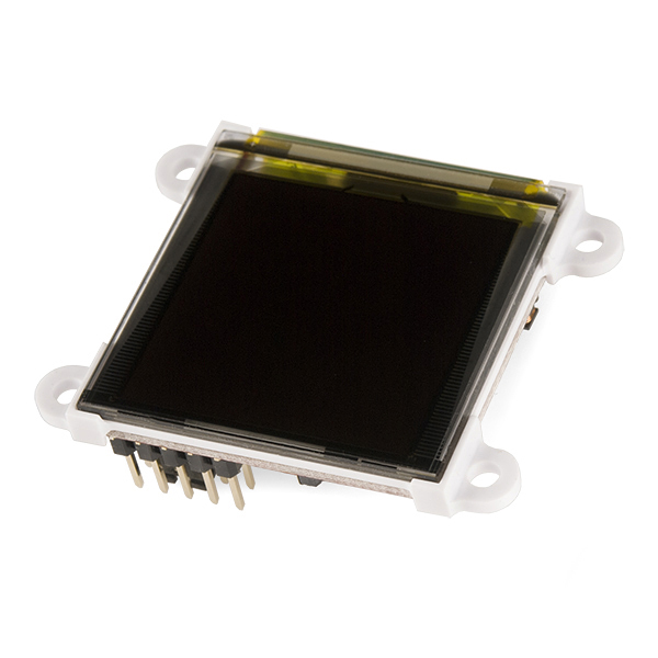
The µOLED-128-G2 is a compact display module from 4D Systems using the latest state of the art Passive Matrix OLED (PMOLED) technology with an embedded GOLDELOX graphics processor that delivers ‘stand-alone’ functionality to any project.
The GOLDELOX chip does the heavy-lifting here, delivering powerful graphics, text, image, animation and more. The module is designed to work out of the box and you are now ready to write your code in 4DGL (a high level 4D Graphics Language) using the 4DGL-Workshop4 IDE (editor, compiler and downloader). That's going to save you a lot of time!
4DGL is a graphics oriented language allowing the developer to write applications in a high level language, syntax similar to popular languages such as BASIC, C and Pascal. The module offers modest but comprehensive I/O features that can interface to serial, analogue, digital, buttons, joystick, sound generation and Dallas 1-wire devices.
In short, the µOLED-128-G2 offers one sweet little module!
Note: It's been brought to our attention that trying to program the 4D screens using an FTDI breakout can damage the driver. You'll need to use the FT232RQ USB to Serial which you can find in the related items below.
- Low-cost OLED display graphics user interface solution
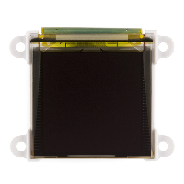
- 128 x 128 resolution, 65K true to life colors, PMOLED screen
- 1.5” diagonal size, 45.5 x 33.5 x 6.1mm. Active Area: 27mm x 27mm.
- No back lighting with near 180° viewing angle
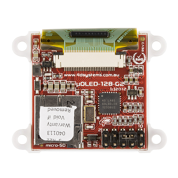
- Easy 10 pin interface to any external device: VCC, TX, RX, GND, RESET, IO1, IO2, 3.3V.
- Powered by the 4D-Labs GOLDELOX graphics processor highly optimised for 4DGL, the high level 4D Graphics Language
- 2 x GPIO ports supports:
- Digital I/O
- A/D converter with 8/10 bit resolution
- Complex sound generation
- Dedicated RTTTL tune engine
- Multi-Switch Joystick
- Dallas 1-Wire
- 10K bytes of flash memory for user code storage and 510 bytes of RAM for user variables (255 x 16bit vars)
- Serial TTL interface with auto-baud feature (300 to 256K baud)
- On-board micro-SD memory card adapter for storing of icons, images, animations, etc. Supports 64Mb to 2Gig micro-SD memory cards
- Comprehensive set of built in high level 4DGL graphics functions and algorithms that can draw lines, circles, text, and much more
- Display full color images, animations, icons and video clips
- Supports all available Windows fonts and characters (imported as external fonts)
- 4.0V to 5.5V range operation (single supply)
- Back plate with 4 x 3mm holes for mechanical mounting.
- 45.6 x 36 x 13.7mm (including corner plates).
Serial Miniature OLED Module - 1.5" (μOLED-128-G2-GFX) Product Help and Resources
Everything You Should Know About HyperDisplay
February 20, 2019
This is a tutorial to go in-depth about the SparkFun HyperDisplay Arduino Library.
Core Skill: Programming
If a board needs code or communicates somehow, you're going to need to know how to program or interface with it. The programming skill is all about communication and code.
Skill Level: Rookie - You will need a better fundamental understand of what code is, and how it works. You will be using beginner-level software and development tools like Arduino. You will be dealing directly with code, but numerous examples and libraries are available. Sensors or shields will communicate with serial or TTL.
See all skill levels
Core Skill: Electrical Prototyping
If it requires power, you need to know how much, what all the pins do, and how to hook it up. You may need to reference datasheets, schematics, and know the ins and outs of electronics.
Skill Level: Competent - You will be required to reference a datasheet or schematic to know how to use a component. Your knowledge of a datasheet will only require basic features like power requirements, pinouts, or communications type. Also, you may need a power supply that?s greater than 12V or more than 1A worth of current.
See all skill levels
Comments
Looking for answers to technical questions?
We welcome your comments and suggestions below. However, if you are looking for solutions to technical questions please see our Technical Assistance page.
Customer Reviews
5 out of 5
Based on 1 ratings:
Great product!
I use it to play video clips on a micro sd card and loop. It works great!
I have had two of these now for a couple of months, Im using them with a Parallax Propeller chip at the moment only for debugging, variable watching etc, though I have also played around with graphics. The are very easy to control in serial slave mode via the propeller micros!
This is really surprising. The serial protocol described in their older literature (no longer available from their site) does not seem to work from many other micros (mostly Atmel, some TI). We unfortunately designed around this paperweight and now have to pull it out after receiving no help from 4D.
It's important to ensure the display is set to serial mode prior to use if you wish to control it via serial commands, from there on it's quite simple.
Since I'm using a Parallax Propeller chip I'm using the SerialDriver Object for communication to the display and can specify the baud rate for communication which is set up when your configure the display for serial slave mode using the application 4D provide. On a 3.3v micro It's also important to have a 10k Resistor across your RX Pin on the micro to Vcc to protect the micros input pin from the 5v signals coming from the display.
As long as you wait for the display to be ready upon power up (I wait 2 seconds) before sending the display the correct data at the right speed and allowing for Ack responses it should work.
This link may be helpful, it links to Arduino, PicAxe and C libraries for serial mode.
http://www.4dsystems.com.au/product/10/120/Development/4D_Workshop_4_IDE/#product_info_documentation_header
How to set a μOLED-128-G2-GFX display to serial slave mode:
Download and install the 4D systems workshop 4 from this page: http://www.4dsystems.com.au/product/10/120/Development/4D_Workshop_4_IDE/#product_info_documentation_header Connect your 4D programming cable to the display, plug it into a USB port.
Run the 4D systems workshop 4 app, select NEW, then choose μOLED-128-G2-GFX from the list of displays, click next.
Click the -> arrow for the serial environment.
Click TOOLS, then click SPE Load button.
Your μOLED-128-G2-GFX is now in serial slave mode.
I imagine the instructions would be the same for the other displays except you would choose the model display you have.
If anyone is interested I'll explain how to load 2 images onto a uSD Card via Graphics Composer and then an explanation of the serial commands used to display them. It's very simple.
Or read this:
http://www.4dsystems.com.au/downloads/Application-Notes/4D-AN-G5002-Serial-Displaying-Image-Video-Animation-Goldelox-REV1.pdf
I interfaced a uOLED-128-G1 with a PIC 24F recently. It took me a while to figure out how to send the commands. Overall, it was easy to operate and easy to write new commands for displaying different graphics.
I could not figure out how to display the pretty gauges and progress bars using Goldelox.
Experimenting with the HTU21D Humidity Sensor Breakout and μOLED-128-G2-GFX and im happy with the results :D
Vid 1 - HTU21D Humidity and 4D Systems uOLED-128-G2 http://youtu.be/8JRTymzHmoM
Vid 2 - HTU21D Temp and 4D Systems uOLED-128-G2 http://youtu.be/3qJeOc7OALg
Actually I'm using the 4D Breakout Board for FT232RQ USB to Serial, also bought from Spark Fun lol
Oh, another good point, the 4D programming cable also works fine to program the Propeller chips as long as you step down the 5v to 3.3v, i'm using a Propeller P8X32A Breakout also bought here and so connect it to the vcc on the breakout, works great!
Some of the documentation images seem to show the microSD card slot behind the 'top' of the screen, others seem to indicate the card slot is behind the 'bottom'. Can I get some clarification on this from someone who has played with one? Thanks!
orientation can be set through programming.
Neat application for the 128-G2:
http://www.digitalspy.com.au/odd/news/a449878/worlds-smallest-arcade-machine-sets-guinness-world-record-picture.html
www.youtube.com/watch?v=MZz6NWQfQok (0:28 onwards)
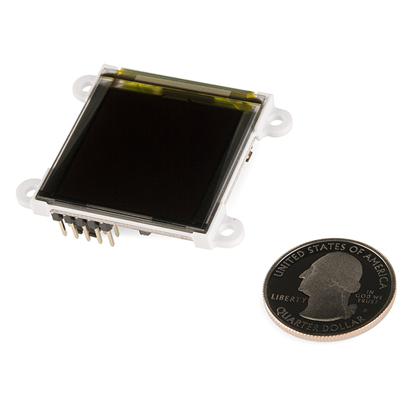
No ruler? Or am I just blind?
The ruler is a lie.
As is the cake...
"It's been brought to our attention that trying to program the 4D screens using an FTDI breakout can damage the driver. You'll need to use the FT232RQ USB to Serial which you can find in the related items below."
Why would they damage the driver? Is it because the headers are not pin-to-pin compatible (and they would need to be switched around)?
I believe about a year ago that 4D Systems required you to use "their" programming device in order to NOT void the warranty for the device.
I own several of their devices and have used "their" programmer without any issues. I do remember seeing something posted at the 4D Systems forum/website stating "why" you needed to use their programmer (something about reset issues?). I'll do more checking as I will be "annoyed" if I need to purchase another programmer due to pins being changed (if that is the case).
Any updates on this? I have the screen and am afraid to get it all hooked up now :/