- Home
- Product Categories
- Audio
- SparkFun MP3 Breakout - VS1063


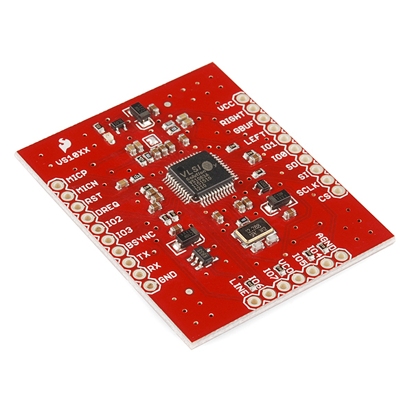
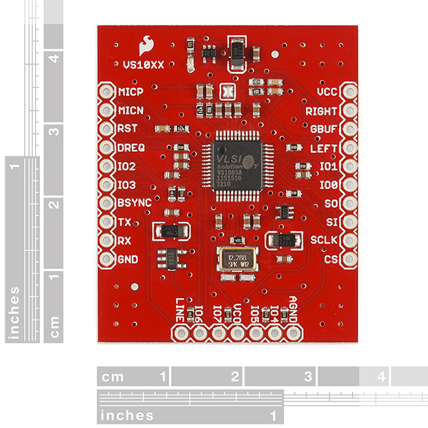
SparkFun MP3 Breakout - VS1063
VS1063 is an easy-to-use, versatile encoder, decoder and codec for a multitude of audio formats. With this breakout board, it's easy to drop it into any project. The VS1063 is capable of decoding Ogg Vorbis/MP3/AAC/WMA audio and encoding MP3, IMA ADPCM and user-loadable Ogg Vorbis. This breakout can also drive 30 ohm headphones with no additional power supply..
- Separate Audio and Digital 3.3V supplies
- Onboard 12.288MHz oscillator* 1.5 x 1.75" (38 x 44.5mm)
SparkFun MP3 Breakout - VS1063 Product Help and Resources
Core Skill: Soldering
This skill defines how difficult the soldering is on a particular product. It might be a couple simple solder joints, or require special reflow tools.
Skill Level: Rookie - The number of pins increases, and you will have to determine polarity of components and some of the components might be a bit trickier or close together. You might need solder wick or flux.
See all skill levels
Core Skill: Programming
If a board needs code or communicates somehow, you're going to need to know how to program or interface with it. The programming skill is all about communication and code.
Skill Level: Competent - The toolchain for programming is a bit more complex and will examples may not be explicitly provided for you. You will be required to have a fundamental knowledge of programming and be required to provide your own code. You may need to modify existing libraries or code to work with your specific hardware. Sensor and hardware interfaces will be SPI or I2C.
See all skill levels
Core Skill: Electrical Prototyping
If it requires power, you need to know how much, what all the pins do, and how to hook it up. You may need to reference datasheets, schematics, and know the ins and outs of electronics.
Skill Level: Rookie - You may be required to know a bit more about the component, such as orientation, or how to hook it up, in addition to power requirements. You will need to understand polarized components.
See all skill levels
Comments
Looking for answers to technical questions?
We welcome your comments and suggestions below. However, if you are looking for solutions to technical questions please see our Technical Assistance page.
Customer Reviews
2.5 out of 5
Based on 2 ratings:
1 of 1 found this helpful:
Great Audio Encoder/Decoder Chip
I bought this board mainly for a future project where I will be needing bidirectional audio. As a simple test I modified the sample driver from the VLSI website "Microcontroller Playback and Recording Example using VS1063" to work with my microcontroller (ESP8266) and was able to play back an MP3 file I had stored in flash memory.
A few things I don't like about this board are:
The form factor - You can't use this on a breadboard, it is two wide, forcing me to use two breadboards, additionally they have the 7 pins going along the bottom which forced me to solder a header going the opposite way.
Only the XCS chip select pin (Labeled CS on the board) is broken out from the VS1063 while the XDCS pin is not, which forces you to use SM_SDISHARE mode where the SCI and SDI share the same chip select. This isn't good for when you are using other devices on the same SPI bus because when your chip select is low the SDI will be active, so if you tried to talk to other SPI devices with your microcontroller, the VS1063 SDI will be getting (and maybe sending) data at the same time. This is literally one extra pin so I'm not sure what the cause of the oversight was on this.
Additionally I managed to blow the board out by accidentally touching the VCC pin on top of the PCB, and this breakout board is out of stock or no longer available? So I will be resorting to buying the raw VS1063 chip from Sparkfun and either replacing the one on this board, or buying a VS1053 breakout board that has the XDCS pin broken out and swapping the chips (the pinouts are the same for the 1053 and 1063, only the various registers are different). Not having the XDCS pin broken out isn't a huge deal for me at the moment because its only 4-5 lines of trivial code to use shared mode instead, and I don't have any other SPI devices, but in the future I will be using a TFT display on the SPI bus so I will have to find another solution where the XDCS pin is broken out.
0 of 1 found this helpful:
Has any one successfully gotten this board to work. ?
I bought 2 of these boards and for weeks I still can't get this board to respond to a simple spi command.
I thought the first board was bad so i got another one and this new one still doesn't work.
I order this board along with the second order and this one works at first go. No issues. https://learn.sparkfun.com/tutorials/mp3-player-shield-hookup-guide-v15?_ga=1.219840540.462715524.1431637947
I started researching this and there is some confusion with vlsi solution saying some of these board has wire missing that needs to be pull up to vdd. I'm disappointed with this product because i ask sparkfun to test this board before they send it to me and clearly they didn't test it.
If there is a known issue with this board then why are they still selling it on the website. Why hasn't it been removed.
I'm sorry, but we do not offer hand testing of products for customer purchases. It's simply not an option we can support. Though those boards are hand tested before being released from our production process. Each unit is checked to ensure it plays a proper test sample out of a speaker. To have 2 units over 2 orders that are both not working is strange. Please contact our support team. They'll be happy to help you trouble shoot. We will likely need to pull both boards back for inspection and testing. If there is a manufacture defect found, we'll certainly help you with that.
Is this out of stock or out of production?
Can I simply connect this and use it without any programming etc? i.e. is there a hardware mode etc?
How many layers does this board have? 4?
Nah, it's just a 2-layer board.
I'm trying to understand how is the ground pin connected (in the eagle files)... to me it looks unconnected, but I'm new to this stuff... is it really so?
Usually a ground plane. By default Eagle doesn't always show you the ground plane, but basically anywhere that doesn't have a trace is just a big copper plane that is usually used for ground. This is the case on both sides of the board. So it may just look like a small wire to nowhere, but its going to the ground plane.
I see, thanks for the clarification!
Anyone tried reprogramming the VS1063 directly? I'm wondering if I can download the VLSI VSIDE and reprogram the VS1063 on this board. http://www.vlsi.fi/en/support/software/vside.html
what voltage is needed at VCC? ive heard 3.3v and 5v and really dont want to blow up the chip!
Good question! The max of VCC is set by the max of the on-board regulators, which'd be about 6V (the max of the SP6214 2.8 and 1.8V regulators). The minimum of VCC would be about 3.3V.
I have a question about the patch. Are patch permanent? In other word does the patch modify the ROM or do I need to provide the patch each time I power it on? From what I understand from http://mpflaga.github.io/Sparkfun-MP3-Player-Shield-Arduino-Library/#Plug_Ins is that I need to keep the patch stored on the SD. And each time the system is powered up the patch is applied but not stored in the VS1063 ROM. If so, is there a way to store the patch on arduino instead of the SD? Thank you
It's my understanding (subject to being wrong) that no, patches are not permanent, which is why you load them after every powerup. If you have the space (there's only 32K total), there's no good reason why you couldn't store it in the Arduino's flash and load it from there. Also note that if you don't need the specific features of a patch, we've had good luck with the bare ROMs (in other words, we usually don't need the patches).
EDIT: more authoritative answer: no the patches are not permanent and if you wish to use them they must be loaded on each powerup of the VS1053.
And if anyone, like me, is wondering how to load it from flash: http://arduino.cc/en/Reference/PROGMEM.
There's only one LINE input! Could anyone explain to me how to use the stereo line input? In the ds it looks like the MICP is used as Line 1. Should I use MICP as Line 1, and LINE as Line 2? Thanks
Please read more of the datasheet. You can use MICP and MICN as a single differential input, or set up the registers to use it as left and right inputs.
Please identify a compatible microphone and add it to the related products section.
I ordered the MEMS mic BOB. Can/should I connect GBUFF to MICN to match the VCC/2 floating output of the MEMS mic? The datasheet specs the MIC pins as "self-biasing"... ??
The MEMS puts out 200mV p-p but the datasheet indicates 140mV p-p as a maximum to avoid distortion. Will the MEMS mic damage this module? If not, will the sound quality be ok?
Thanks
Can this board play more than one sound file at a time? If not, can someone recommend a board that can?
Thanks
This chip can only decode one audio file at a time. To do more you'll likely need to step up to a beefier microcontroller, like the Beaglebone or Raspberry Pi, and do it using software commands.