- Home
- Product Categories
- Button
- Metal Pushbutton - Latching (16mm, Red)

Metal Pushbutton - Latching (16mm, Red)
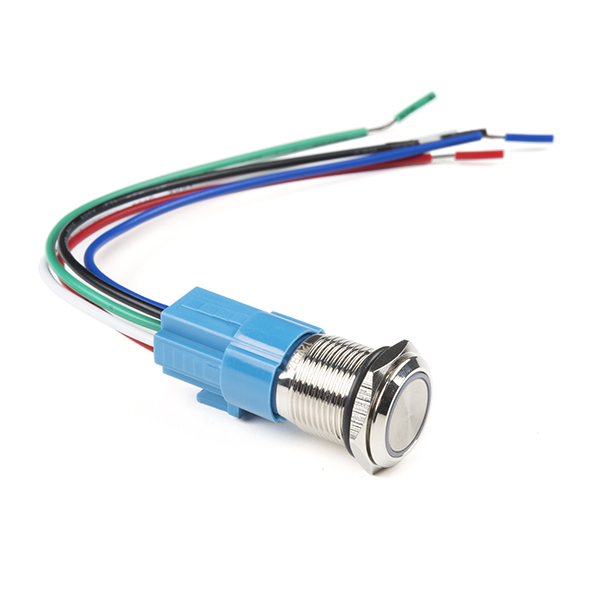
This is a perfect choice if you are in need of a heavy duty push button! These metal push buttons are a very tough, small, panel-mount latching switch with an illuminated red LED ring. It is a SPDT with 16mm threading and 1mm pitch. This button is perfect for basic On/Off functions. Overall length (including leads) is 1.5" and has small solder lugs for connection. These latched buttons are rated up to 3A and 250VAC while the LED is rated for 5-12V.
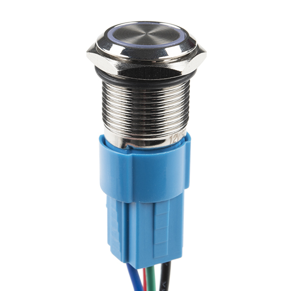
Note: The images for this button show an LED voltage rating of 5V. We have verified that the voltage range for the the LED to be 5-12V. We are currently communicating with our supplier for new documentation. Trust the branding on the button to verify your voltage requirement.
- Stainless Steel Body
- IP65 Weatherproof Rating
- Tamper Resistant
- Latching Operation Type
- Red LED Ring
Metal Pushbutton - Latching (16mm, Red) Product Help and Resources
Wireless Audio Bluetooth Adapter w/ BC127
December 14, 2017
Build a custom wireless audio Bluetooth adapter using BlueCreation's BC127 and add it to your old speaker system!
Pinout
The pushbuttons (like the momentary https://www.sparkfun.com/products/11966 or latching https://www.sparkfun.com/products/11971 ) have an indication of the pinout of the buttons on the side of the plastic molding. One way to test the switch is to use a multimeter turned to the continuity setting. Here are what the pins (not in any particular order associated with the pushbutton's spades):
+ = LED Anode
- = LED Cathode
C = "Common Ground"
NC = Normally Closed
NO = Normally Open
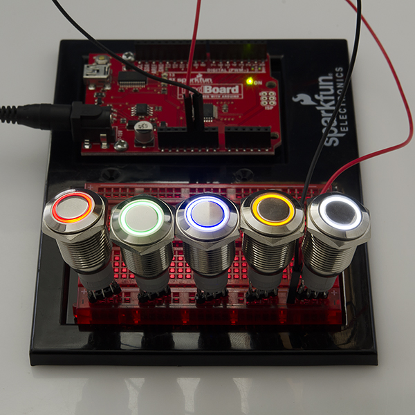
One way to light the LED on the metal push button would require you to wire it so that when you press down on the button, the led would light up. You would need 5V to light the LED ring. It can be lit up with a smaller voltage but the LED won't light up as bright.
To connect the battery to the button so that it only lights when the switch is pressed down (momentary or latched), you would connect 5V to the "+" pin on the switch. This is assuming that your system is using the same voltage source that is 5V. Then from the "+" pin, you would wire it to the normally open (NO) pin.
Another wire would be connected from the "-" pin to the C pin. The C pin would essentially be connected to your ground. So as you press down on the button, it would flip the switch and complete the circuit from the normally closed (NC) pin to normally open (NO) pin while lighting the LED ring at the same time. It might be a good idea to use a current limiting resistor (like standard 330Ohm resistor) if you are using 5V directly from your power supply. The LED won't be as bright but you also wouldn't be reducing the life of the LED. I am not sure of the electrical characteristics of the LED that is in the pushbutton.
Core Skill: DIY
Whether it's for assembling a kit, hacking an enclosure, or creating your own parts; the DIY skill is all about knowing how to use tools and the techniques associated with them.
Skill Level: Noob - Basic assembly is required. You may need to provide your own basic tools like a screwdriver, hammer or scissors. Power tools or custom parts are not required. Instructions will be included and easy to follow. Sewing may be required, but only with included patterns.
See all skill levels
Core Skill: Electrical Prototyping
If it requires power, you need to know how much, what all the pins do, and how to hook it up. You may need to reference datasheets, schematics, and know the ins and outs of electronics.
Skill Level: Competent - You will be required to reference a datasheet or schematic to know how to use a component. Your knowledge of a datasheet will only require basic features like power requirements, pinouts, or communications type. Also, you may need a power supply that?s greater than 12V or more than 1A worth of current.
See all skill levels
Comments
Looking for answers to technical questions?
We welcome your comments and suggestions below. However, if you are looking for solutions to technical questions please see our Technical Assistance page.
Customer Reviews
No reviews yet.
-------------------- Tech Support Tips/Troubleshooting/Common Issues --------------------
Pinout
The pushbuttons (like the momentary https://www.sparkfun.com/products/11966 or latching https://www.sparkfun.com/products/11971 ) have an indication of the pinout of the buttons on the side of the plastic molding. One way to test the switch is to use a multimeter turned to the continuity setting. Here are what the pins (not in any particular order associated with the pushbutton's spades):
One way to light the LED on the metal push button, you would need to wire it so that when you press down on the button, the led would light up. You would need 5V to light the LED ring. It can be lit up with a smaller voltage but the LED won't light up as bright.
To connect the battery to the button so that it only lights when the switch is pressed down (momentary or latched), you would connect 5V to the "+" pin on the switch. This is assuming that your system is using the same voltage source that is 5V. Then from the "+" pin, you would wire it to the normally open (NO) pin.
Another wire would be connected from the "-" pin to the C pin. The C pin would essentially be connected to your ground. So as you press down on the button, it would flip the switch and complete the circuit from the normally closed (NC) pin to normally open (NO) pin while lighting the LED ring at the same time. It might be a good idea to use a current limiting resistor (like standard 330Ohm resistor) if you are using 5V directly from your power supply. The LED won't be as bright but you also wouldn't be reducing the life of the LED. I am not sure of the electrical characteristics of the LED that is in the pushbutton.
Hey, i am new to this. can you tell me what latch everyone is talking about?
The features describe the operation as having two NO contacts and two NC contacts: 1NO1NC/2NO2NC. However, in the comments section of the momentary red switch, RobertC.'s description implies there is only one circuit when he says of the pins
which is what I would have assumed without any description. I know these things are really simple but a wiring diagram or just a better picture of the pins' labels would clear this up.
Although it's hard to see in the picture, the legs are labeled on the gray plastic housing- the outer two are + and - for the LED ring, and the inner three are C1, NO1, and NC1
I had some drama wiring this switch, but finally managed to get it all working. In this example I have it connected to Arduino 5V An example if you want to control the LED and check switch state:
Connect positive terminal (+) to PIN 4 (OUPUT pin to switch the LED on/off). Connect negative terminal (-) to GND. Connect common (C) to 5V rail. Connect normally open to PIN 3 (INPUT for switch).
CODE: const int SWITCH_LED = 4; const int SWITCH = 3;
volatile boolean switch_state = LOW;
void setup() { pinMode(SWITCH_LED, OUTPUT); pinMode(SWITCH, INPUT); digitalWrite(SWITCH_LED, LOW); }
void loop() { if (digitalRead(SWITCH) == LOW) { digitalWrite(SWITCH_LED, LOW); } else { digitalWrite(SWITCH_LED, HIGH); } delay(10); }
Hope this is helpful: (1) the holes at the end of the terminals are very small. Its a 3A switch but even 22AWG hook-up wire won't fit w/out cutting a few strands (24AWG fit ok). (2) Led works directly from 24Vdc (has built in res). (3) As mentioned, center button is very small for a switch this size (to make room for the LED ring I suppose). Overall a high quality, good looking latching switch for the money if you don't have high current needs.
Does this have an internal pull-up resistor?
I just bought one of these, and I must admit I was disappointed for two reasons:
I was going to use this to turn on power to a device, but it is completely unacceptable for this purpose, sending brief pulses of power to my device when it fails to latch.
What is the difference between latching buttons and momentary buttons?
What Kamiquasi said. Also think "click on / click off" like a ballpoint pen.
Momentary: Makes a connection when pressed, breaks it when you let go.
Latching: Makes a connection when pressed, remains in that state when you let go. To break the connection, press it again.
( Swap out "make" and "break" for the NC/normally closed pins, which for the latching version may additionally require you to let go of it again depending on actual construction. )
From the datasheet it appears as if you have a 3D Model of this switch ready to go but I was unable to find it on the GitHub repo of models. If possible I'd like to get access to the model for my project.