- Home
- Product Categories
- Other
- SparkFun RedBot Buzzer

SparkFun RedBot Buzzer
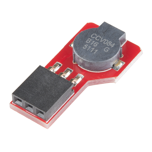
This buzzer is an add-on for your RedBot that gives your robot the ability to make awesome beep-boop noises or alerts when something interesting (or terrible) happens. The buzzer works by making use of two I/O pins on a controller board to create different noises based on the different frequency of I/O toggling. If you are using this buzzer on a RedBot, simply plug it in to one of the many 3-pin I/O ports and get your robot to make some noise.
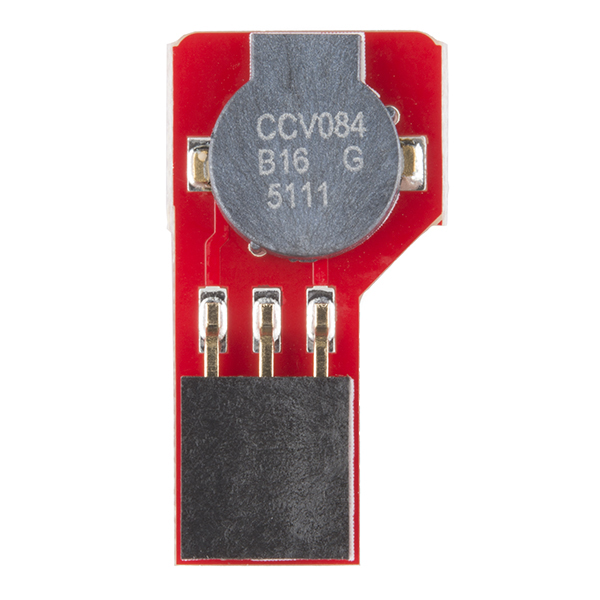
The buzzer has a 3-pin header which connects directly to the RedBot Mainboard or via male to female jumper wires. Use the included RedBot library to detect sound alarms and make some noise.
Check out the entire RedBot family of products!
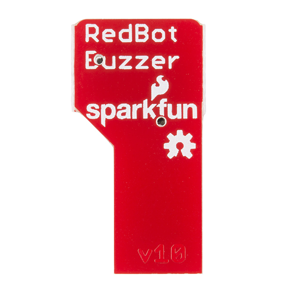
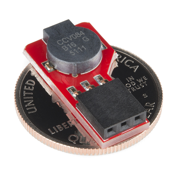
- 1.0" x 0.52" (25.33 x 13.37 mm)
SparkFun RedBot Buzzer Product Help and Resources
Experiment Guide for RedBot with Shadow Chassis
May 28, 2015
This Experiment Guide offers nine experiments to get you started with the SparkFun RedBot. This guide is designed for those who are familiar with our SparkFun Inventor's Kit and want to take their robotics knowledge to the next level.
Wireless Gesture Controlled Robot
April 25, 2019
Control the RedBot wirelessly based on the movement of your hand using an accelerometer, Arduino, and XBees!
Core Skill: Robotics
This skill concerns mechanical and robotics knowledge. You may need to know how mechanical parts interact, how motors work, or how to use motor drivers and controllers.
Skill Level: Noob - You will be required to put together a robotics kit. Necessary parts are included and steps will be easy to follow. You also might encounter basic robotics components like bearings, mounts, or other hardware and need a general idea of how it goes together.
See all skill levels
Core Skill: Electrical Prototyping
If it requires power, you need to know how much, what all the pins do, and how to hook it up. You may need to reference datasheets, schematics, and know the ins and outs of electronics.
Skill Level: Rookie - You may be required to know a bit more about the component, such as orientation, or how to hook it up, in addition to power requirements. You will need to understand polarized components.
See all skill levels
Comments
Looking for answers to technical questions?
We welcome your comments and suggestions below. However, if you are looking for solutions to technical questions please see our Technical Assistance page.
Customer Reviews
No reviews yet.
How much does the volume change when you switch from 3.3V to 5V?
I'm thinking about using one of these with an arduino; should be fairly easy to hook up with jumper wires. My only concern is that the datasheet says that the max current is 120 mA, way more than an arduino digital pin can handle. However, it looks like the intended use of this is to hook it up directly to a digital pin. Am I missing something?
It will work with a digital IO pin, but you'll get a somewhat quieter sound than you would if you were to, say, use a transistor switch to give it its full current range. It's still pretty loud, however: loud enough to be heard anywhere in a small room, for example.
Thanks, that makes sense and I'm glad it is still plenty loud. One more thing, I know that you can kill a digital IO pin by putting too much current through it, but I gather this is not a problem here (from my googling, seems like everyone does it without a problem). My electronics understanding isn't very deep, so is there a simple reason why this doesn't happen here?
My experience has been that, with the tougher microcontrollers like the Atmega328 on the RedBot board or Arduino Uno, you can short a pin to ground without killing it. I'm guessing that this is because the drive circuit's output impedance is high enough that it self limits the current to a non-destructive level. For more info about what this means look into Thevenin equivalent circuits. That will help you understand.
Why does the description say: "The buzzer works by making use of two I/O pins on a controller board"?
Should say one I/O pin. + PWR and GND of course
No sound clip or youtube video of what this thing actually sounds like?
Quicksilver, I think that Digikey sells the buzzer unit by itself. Search for their part #102-1265-1-ND.
Under $3
It would be really cool if you could sell this buzzer by itself, I feel like a tool ordering a single component off of DigiKey sometimes...
Can some one provide a snippet of Arduino code or point me to some example Arduino code for operating this RedBot buzzer? I've looked through the Redbot library and tutorials, but I can't seem to find anything on how to get this to work.
Simply use Arduino's built-in tone() commands. The buzzer board is made as it is to plug nicely onto the headers on the RedBot mainboard.
Ah, OK. That makes sense. Thank you for the quick reply.
For those of you who purchased a RedBot and are thinking of upgrading it with some of the new gadgets for it like the Wheel Encoder, they changed the "standard" layout of the line-follower sensors. The old setup for the (left, center, right) sensors was (A2, A3, A6) and it changed to (A7, A6, A3), probably because they were running out of digital pins and they wanted to move one of the line-following sensors to A7 which is analog-only. This is not a big deal as long as you realize the issue exists.
Making your bot match whatever version of the library and demo code you have is easy - just move some wires if needed. Marking the library match however your bot is wired is also easy: find the 3 lines in a header file or code:
where NN represents 3 different numbers, and change them to match your setup wiring, if needed. These are normally the only references to the pin numbers.
With the new gadgets, RedBot is using all available pins (which doesn't rule out adding a port expander on the I2C bus):
Left Motor: D2, D4, D5 Right Motor: D7, D8, D6 Line Sensors (l, c, r): A7, A6, A3 Wheel Encoders (l, r): A2/D16, D3 Bumper Sensors (l, r): D10 D11 Serial port: D0, D1 XBEE serial port: A0/D14, A1/D15 Accelerometer: A4/D18, A5/D19, although I2C can handle a practically unlimited number of devices on the bus. Buzzer: D9 User LED: D13 User Button: D12 on newer mainboards. D12 is brought out at the ICSP header so adding a button isn't hard.
The old setup sometimes used up to 4 unspecified "servo" devices on PWM pins D3, D9, D10, and D11. If you want that now, you'll need to choose what devices you want to connect.